BLUE JAY DCEM Multi Channel DC Energy Meter User Manual
Read me
When you use DCEM Multi-channel DC Energy Meter, be sure to carefully read this user manual, and be able to fully understand the implications, the correct guidance of operations in accordance with user manual, which will help you make better use this DC Energy Meter, and help to solve the various problems at the scene.
- Before the meter turning on the power supply, be sure that the power supply within the provisions of the instrument;
- When installation, the current input terminal must non-open, voltage input terminals must Non-short circuit;
- Be sure the instrument wiring consistent with the internal system settings;
- When communicating with the PC, instrument communication parameters must be consistent with the PC
- Please read this user manual carefully
- Please save this document
SUMMARIZE
BJ-DCEM meter is an advanced solution for multi-channel energy metering in DC system. It can visually display voltage, current, power data and energy cumulative data. With a panel keypad, it can set voltage display parameters and the hall CT parameters.
With RS485 communication interface, BJ-DCEM can be connected to the monitoring center. It is a high-performance automatic meter suitable for industrial and mining enterprises, civil construction, building automation.
These series can measure the power parameters in power grid:
| Current | 0.000 ~ 500A (Depends on the Hall CT) |
| Voltage | 0.0 ~ 1000V |
| Active power | 0.000 ~ 9999KW |
| Energy | 0.00Wh ~ 999999999Wh |
SPECIFICATIONS
- Reference standard:
Basic electricity: IEC 61557-12:2007 Active energy: IEC 62053-21:2003 - Accuracy standards
Parameter Accuracy Current 0.5%fs Voltage 0.5%fs Active power 1%fs Energy 1%fs - Input
Current: Hall Effective CT, aux +/-15VDC, 4V signal input - Load
Current: <0.5VA / phase (rated 5A) - Overload
Current: 1.2 times rated continuous; 1 seconds for 10 times the rated Voltage: 1.2 times rated continuous; 10 seconds for 2 times the rated - Dielectric strength
IEC/EN 61010-1:2010 2kV AC RMS 1 minute, between input / output / case / power supply - Work environment
Temperature: -20℃~ +60℃ Humidity: RH 20%~95%(No condensation) - Protection
Panel: IP40 - Storage Conditions
Temperature: -25℃~+70℃ Humidity: RH 20%~95% - Power Supply
DC 20-60V Maximum power consumption 4VA - Dimensions
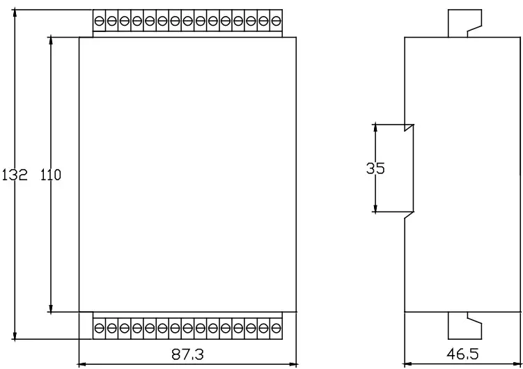
L × H × D =87.3X132X46.5mm (with wiring terminal)
INSTALLATION AND START-UP
 The manual you hold in your hands contains information and warnings that the user should respect in order to guarantee a proper operation of all the instrument functions and keep its safety conditions. The instrument must not be powered and used until its definitive assembly is on the cabinet’s door.
Whether the instrument is not used as manufacturer’s specifications, the protection of the instrument can be damaged.
When any protection failure is suspected to exist (for example, it presents external visible damages),the instrument must be immediately powered off. In this case contact a qualified service representative.
Installation
Mounting
Instrument is to be mounted on 35mm Din-rail. Keep all connections inside the cabinet.
Note that with the instrument powered on, the terminals could be dangerous to touch and cover opening actions or elements removal may allow accessing dangerous parts.
Therefore, the instrument must not be used until this is completely installed.
Notes:
Auxiliary power:
DCEM meter with AUX power input, if not for a special statement, we provide the DC 20-60V power interface for standard products. Please ensure that the auxiliary power match meter access to prevent damage to the product.
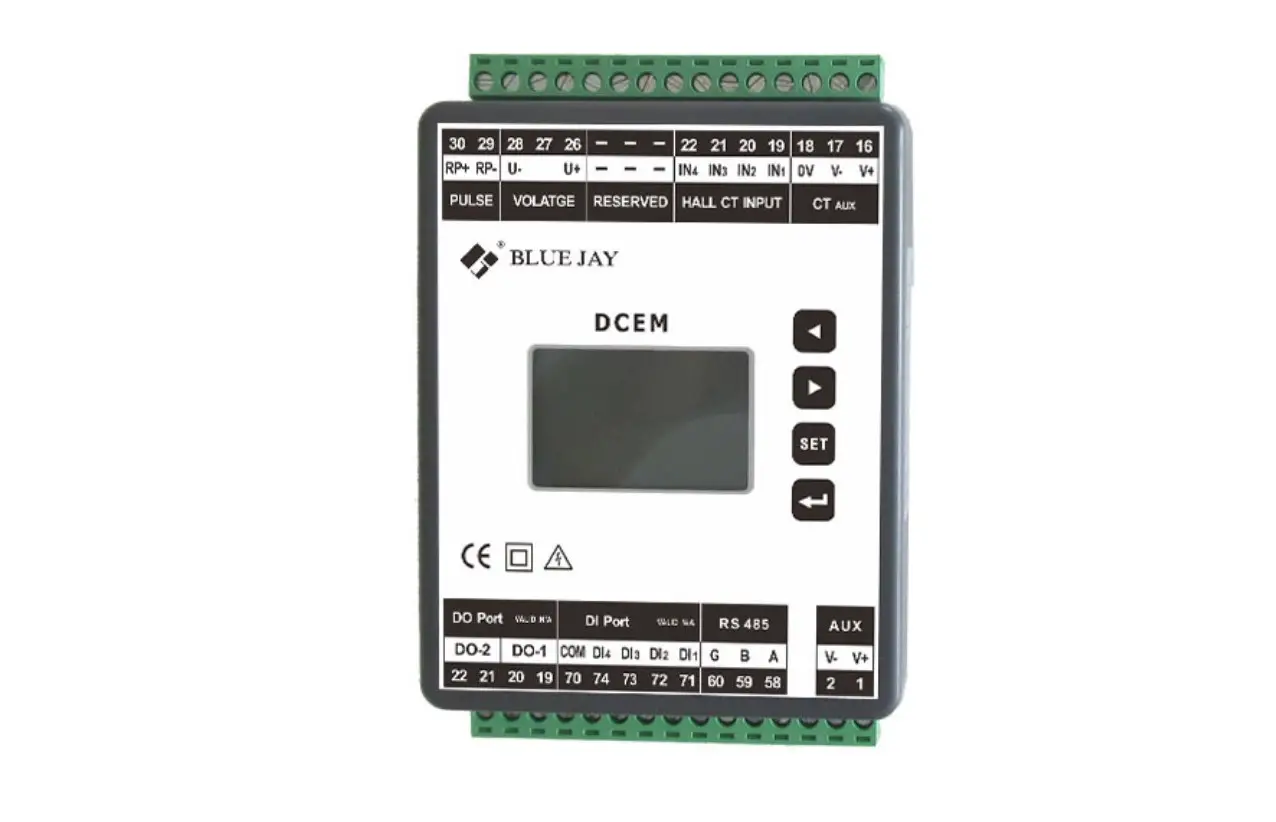
Connection terminal and drawing for BJ-DCEM
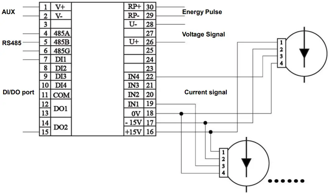
Notes:
The current input pin need to access the Hall CT, and output signal of CT is 0-4VDC, Hall CT need +/-15V AUX power, on the meter pin 16, 17 provide the AUX.
Wiring diagram may be changed due to the special requirements of customers order, please refer the label on the rear part.
If you are or sure or signs unclear please contact:
Blue Jay Technical Support: [email protected]
SETUP PROCEDURE
Key operation
![]() for screen switch or value increase/decrease
for screen switch or value increase/decrease![]() for menu enters or exit
for menu enters or exit![]() for enter next menu or confirm the chang
for enter next menu or confirm the chang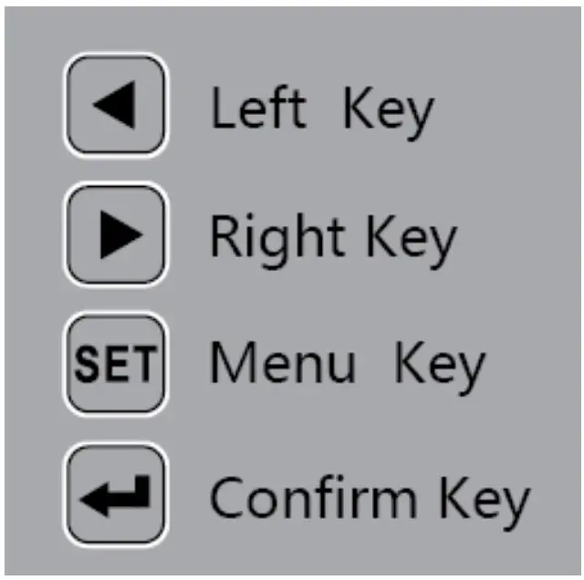
Show electric parameters
When the DCEM in monitor screen, user can use keypad switch shows the electrical parameters, when press “←” or “→” to switch another screen, screen roller logic as following: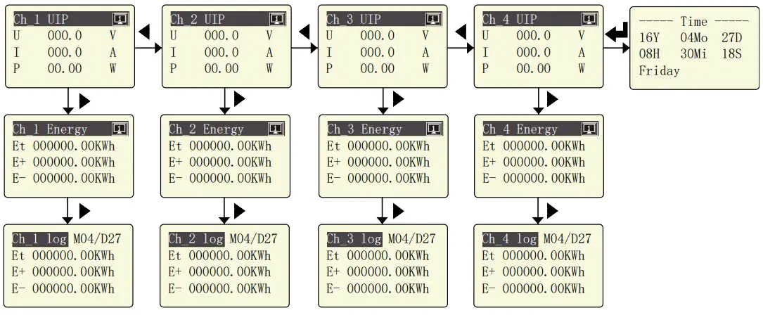
Parameters Setting
The SETUP procedure of the BJ-DCEM is performed by means of several SETUP options. When into the SETUP, use the keyboard to select different options and enter required variables:
Press the key SET can enter the parameter setting. the screen ask access password (Default is 0001), then press can enter the menu.
The operation menu logic as following: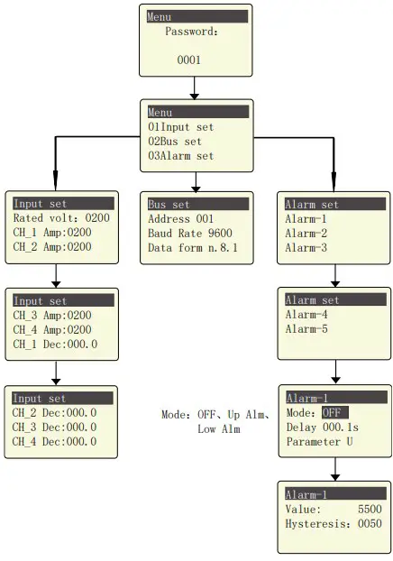
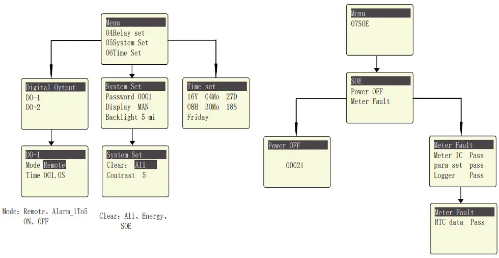
Menu Structure
Time settingYear SOEPower OFF
| level 1 | Level 2 | Level 3 | Level 4 | Description |
| Input Setting | Rated volt | 48 | / | Voltage metering range |
| CH_1~4 Amp | 100 | / | Current metering range | |
| CH_1~4 Dec | / | / | Decimal point position | |
| Comm Setting | Address | 1~247 | / | Default 0001 |
| Baud Rate | 2400 / 4800 / 9600 | / | Default is 9600 | |
| Check format | n.8.1 / o.8.1 / e.8.1 | / | Factory default (n.8.1) | |
|
Alarm Setting |
Alarm_1~5 | Mode | OFF / Upper Limit / Lower Limit | Total three mode |
| Delay | / | Alarm triggered time delay, Default 001.0s | ||
| Parameter | U / I / P / … | Alarm triggered parameters | ||
| Value | 0~9999 | Default is 5500 | ||
| hysteresis | 0~9999 | Default is 0050 | ||
| Digital Output |
DO_1~2 | Mode | Remote Alarm_1~5 ON / OFF | Total 8 mode |
| Time | 0~999.9 | Alarm triggered time delay. In remote mode is pulse width. Default 000.1s. | ||
| System Settings | Password | 0~9999 | / | Reset user password |
| Display | MAN Number 1~9 | / | Manual switching, or automatic switching in 1~9sec | |
| Backlight | 1~5 | / | LCD backlight duration, | |
| unit is min, default is 5 | ||||
| Clear | All / Energy / SOE | / | Clear the record in meter | |
| Contrast | 1~9 | / | LCD display contrast, default is 5 | |
| 00-99 | / |
Clock setting | ||
| Month | 1~12 | / | ||
| Date | 1~31 | / | ||
| Hour | 00~23 | / | ||
| Minute | 00~59 | / | ||
| Second | 00~59 | / | ||
| Week day | 1~7 | / | ||
| 0-99999 | / | Record the meter power off times | ||
| Meter fault | / | / | See screen description |
PULSE OUTPUT
DCEM provides 1 channel pulse output for the total active energy and total reactive energy.
The host/PLC/DI module can cumulative the data of both the active and reactive power energy sent by the pulse from optocoupler relay.
- Electrical specification: voltage VCC ≤ 48V, Iz ≤ 50mA.
- Pulse: example in 5000 imp / kWh, pulse upto 80ms.
This means: When the meter detect 1 kWh, the meter output 5000 pulse
Note: 1 kWh energy is for secondary side energy data, if there have PT and CT accessed; primary side energy data is “1 kWh ×PT ratio× CT ratio”.
For example: In measure time “T”, the received total pulse is “N”, Primary side input of voltage is 10Kv Primary side input of current is 400A. Secondary side measurement range is 100V and 5A.
In the time “T”, energy accumulated is : N/5000 × 100 × 80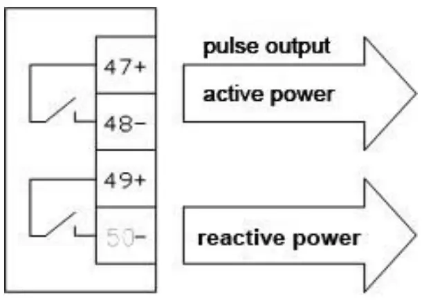
COMMUNICATION PROTOCOL
Connection for the RS485 BUS
The composition of the RS-485 cabling must be carried out with a meshed screen cable (minimum 3 wire), diameter of not less than 0.5mm2 , with a maximum distance of 1,200 m between the BJ194… and the master unit. This Bus may connect a maximum of 32 BJ194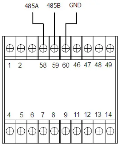
Note
- For communication with the master unit, customers can choose the RS-232 to RS-485 converter to use
- Full range of BJ-194… meter RS485 PIN number is 58,59,60
- Due to product modifications or custom requirements, the interface pin place may be changed. For details, please refer to product label on the rear board
MODBUS © protocol
| Address code | 1 BYTE | Slave device address 1-247 |
| Function code | 1 BYTE | Indicates the function codes like read coils / inputs |
| Data code | 4 BYTE | Starting address, high byte Starting address, low byte Number of registers, high byte Number of registers, low byte |
| Error Check code | 2 BYTE | Cyclical Redundancy Check ( CRC ) |
MODBUS FUNCTIONS
| Code: | Meaning: | Description: |
| FUNCTION 03/04 | Reading of n Words | This function permits to read all the electrical parameters of the BJ194…series. |
| FUNCTION 08 | Clear energy counters | Cleared energy data by the PC (*User also can clear energy counter on meter operation, refer the User Manual related section) |
| FUNCTION 16 | Preset Multiple Registers | Write value in to the relevant register |
Register Address Table
Basic Power Data—Primary Side
| Address | Data | Byte mode | Instruction | |
| 0x00 | U | float | 2 | System Voltage, Unit: V |
| 0x02 | I1 | float | 2 | Current of Channel_1, Unit: A |
| 0x04 | P1 | float | 2 | Power of Channel_1, Unit: W |
| 0x06 | Epz1 | float | 2 | Total Energy of Channel_1, Unit: KWh |
| 0x08 | EP1+ | float | 2 | Total Positive Energy of Channel_1, Unit: KWh |
| 0x0a | EP1- | float | 2 | Total Negative Energy of Channel_1, Unit: KWh |
| 0x0c | I2 | float | 2 | Current of Channel_2, Unit: A |
| 0x0e | P2 | float | 2 | Power of Channel_2, Unit: W |
| 0x10 | Epz2 | float | 2 | Total Energy of Channel_2, Unit: KWh |
| 0x12 | EP2+ | float | 2 | Total Positive Energy of Channel_2, Unit: KWh |
| 0x14 | EP2- | float | 2 | Total Negative Energy of Channel_2, Unit: KWh |
| 0x16 | I3 | float | 2 | Current of Channel_3, Unit: A |
| 0x18 | P3 | float | 2 | Power of Channel_3, Unit: W |
| 0x1a | Epz3 | float | 2 | Total Energy of Channel_3, Unit: KWh |
| 0x1c | EP3+ | float | 2 | Total Positive Energy of Channel_3, Unit: KWh |
| 0x1e | EP3- | float | 2 | Total Negative Energy of Channel_3, Unit: KWh |
| 0x20 | I4 | float | 2 | Current of Channel_4, Unit: A |
| 0x22 | P4 | float | 2 | Power of Channel_4, Unit: W |
| 0x24 | Epz4 | float | 2 | Total Energy of Channel_4, Unit: KWh |
| 0x26 | EP4+ | float | 2 | Total Positive Energy of Channel_4, Unit: KWh |
| 0x28 | EP4- | float | 2 | Total Negative Energy of Channel_4, Unit: KWh |
Float data follow IEEE754, float low bit first, high bit next. (CD AB)
Meter status data
| Address | Data | Byte mode | Instruction | |
| 0x200 | DO | int | 1 | Digital output:Bit 0~1 show channel 1and channel 2 status 0 for open, 1 for closed |
| 0x201 | DI | int | 1 | Digital input:Bit 0~3 show channel 1 to channel 4 status 0 for open, 1 for closed |
| 0x203 | DZ | int | 1 | Alarm conditionBit0~4 show channel 1 to channel 5 status |
| 0x20A | TIME.year | int | 1 | Internal RTC clock:year-month-day-hour-minutes-second-week (Integer, the last char unused) |
| 0x20B | TIME.month | int | 1 | |
| 0x20C | TIME.date | int | 1 | |
| 0x20D | TIME.hour | int | 1 | |
| 0x20E | TIME.minute | int | 1 | |
| 0x20F | TIME.secon d | int | 1 | |
| 0x210 | TIME.day | int | 1 | |
Energy Record Data (max 31 days)
| Address | Data | Byte mode | Instruction | ||
| 0x3000 | MMDD/1 | int | 1 | Record Date(1), BCD code, unit: Month/Day | |
| 0x3001 | Epz1/1 | long | 2 | Total energy record for Channel_1 in Date(1) unit 0.01KWh | |
| 0x3003 | EP1+/1 | long | 2 | Positive energy record for Channel_1 in Date(1) unit 0.01KWh | |
| 0x3005 | EP1-/1 | long | 2 | Negative energy record for Channel_1 in Date(1) unit 0.01KWh | |
| 0x3007 | Epz2/1 | long | 2 | Total energy record for Channel_2 in Date(1) unit 0.01KWh | |
| 0x3009 | EP2+/1 | long | 2 | Positive energy record for Channel_2 in Date(1) unit 0.01KWh | |
| 0x300B | EP2-/1 | long | 2 | Negative energy record for Channel_2 in Date(1) unit 0.01KWh | |
| 0x300D | Epz3/1 | long | 2 | Total energy record for Channel_3 in Date(1) unit 0.01KWh | |
| 0x300F | EP3+/1 | long | 2 | Positive energy record for Channel_3 in Date(1) unit 0.01KWh | |
| 0x3011 | EP3-/1 | long | 2 | Negative energy record for Channel_3 in Date(1) unit 0.01KWh | |
| 0x3013 | Epz4/1 | long | 2 | Total energy record for Channel_4 in Date(1) unit 0.01KWh | |
| 0x3015 | EP4+/1 | long | 2 | Positive energy record for Channel_4 in Date(1) unit 0.01KWh | |
| 0x3017 | EP4-/1 | long | 2 | Negative energy record for Channel_4 in Date(1) unit 0.01KWh | |
| 0x3019 | MMDD/2 | int | 1 | Record Date(2), BCD code, unit: Month/Day | |
| 0x301A | Epz1/2 | long | 2 | Total energy record for Channel_1 in Date(2) unit 0.01KWh | |
| 0x301C | EP1+/2 | long | 2 | Positive energy record for Channel_1 in Date(2) unit 0.01KWh | |
| 0x301E | EP1-/2 | long | 2 | Negative energy record for Channel_1 in Date(2) unit 0.01KWh | |
| 0x3020 | Epz2/2 | long | 2 | Total energy record for Channel_2 in Date(2) unit 0.01KWh | |
| 0x3022 | EP2+/2 | long | 2 | Positive energy record for Channel_2 in Date(2) unit 0.01KWh | |
| 0x3024 | EP2-/2 | long | 2 | Negative energy record for Channel_2 in Date(2) unit 0.01KWh | |
| 0x3026 | Epz3/2 | long | 2 | Total energy record for Channel_3 in Date(2) unit 0.01KWh | |
| 0x3028 | EP3+/2 | long | 2 | Positive energy record for Channel_3 in Date(2) unit 0.01KWh | |
| 0x302A | EP3-/2 | long | 2 | Negative energy record for Channel_3 in Date(2) | |
| unit 0.01KWh | |||||
| 0x302C | Epz4/2 | long | 2 | Total energy record for Channel_4 in Date(2) unit 0.01KWh | |
| 0x302E | EP4+/2 | long | 2 | Positive energy record for Channel_4 in Date(2) unit 0.01KWh | |
| 0x3030 | EP4-/2 | long | 2 | Negative energy record for Channel_4 in Date(2) unit 0.01KWh | |
| 0x3032- 0x304A | Date(3) data block, format same as above | ||||
| 0x304B- 0x3063 | Date(4) data block, format same as above | ||||
| 0x3064- 0x307D | Date(5) data block, format same as above | ||||
| …… …… …… | ………… ………… ………… | ||||
| 0x32EE- 0x3306 | Date(31) data block, format same as above | ||||
Notes: Date (1) mean the last day before current time, Date(31) for the oldest record time point, DCEM will automatic cycle record the data, mean the oldest data will loss one by one
Energy record Data max 31 days
| Address | Data | Byte mode | Instruction | |
| 0x5000 | int | 1 | Total power off number of times | |
| 0x5001 | int | 1 | Meter fault alarm | |
Notes: in address 0x5001, following chart show the related alarm condition
| Bit | Meter Fault | Abnormal | Normal |
| D0 | Metering IC error | 1 | 0 |
| D1 | reversed | ||
| D2 | reversed | ||
| D3 | reversed | ||
| D4 | Setting config. area error | 1 | 0 |
| D5 | Logger record area error | 1 | 0 |
| D6 | Real-time data area error | 1 | 0 |
| D7 | reversed | ||
| D8 | reversed | ||
| D9 | reversed | ||
| D10 | reversed | ||
| D11 | reversed | ||
| D12 | reversed | ||
| D13 | reversed | ||
| D14 | reversed | ||
| D15 | reversed |
SAFETY CONSIDERATIONS
All installation specification described at the previous chapters named:
INSTALLATION AND STARTUP, INSTALLATION MODES and SPECIFICATIONS.
Note that with the instrument powered on, the terminals could be dangerous to touching and cover opening actions or elements removal may allow accessing dangerous parts. This instrument is factory-shipped at proper operation condition
MAINTENANCE
The DCEM does not require any special maintenance. No adjustment, maintenance or repairing action should be done when the instrument open and powered on, should those actions are essential, high-qualified operators must perform them.
Before any adjustment, replacement, maintenance or repairing operation is carried out; the instrument must be disconnected from any power supply source.
When any protection failure is suspected to exist, the instrument must be immediately put out of service. The instrument’s design allows a quick replacement in case of any failure.
TECHNICAL SERVICE
For any inquiry about the instrument performance or any failure Contact to Blue Jay’s technical service.
Blue Jay – After-sales service
E-mail : [email protected]
Tel: +0086-023-67628702
www.cqbluejay.com
Add: 1802,Building 2,No.88,Jianxin East Road,Chongqing,400020,China
Email:[email protected]


