
BJ-MCM400 Multi Channel Circuit Metering System

Product Information
The Multi-channel Circuit Metering System BJ-MCM400 is a compact and robust metering solution that enables reliable monitoring of building electrical loads at a low installation cost-per-point. The unit performs real-time metering and measures energy consumption o 4 channels circuits for three-phase circuits. The MCM400 meters are ideal for multi-tenant or departmental metering applications within office towers, condominiums, apartment buildings, shopping centers, and other multi-user environments.
- Advanced communication options including Modbus via RS485, I/O communications provide for extensive reliable data exchange
- Multiple units can be connected together to meter an unlimited number of circuits
Specifications
The specifications of the BJ-MCM400 Multi-channel Circuit
Metering System are as follows:
- Version: 1.31
- Power supply: Within the provisions of the instrument
- Current input terminal: Non-open during installation
- Voltage input terminal: Non-short circuit during installation
- Instrument wiring: Consistent with the internal system settings
- Communication parameters: Must be consistent with the PC when communicating with the PC
Safety Considerations
Be sure to read and follow the safety considerations in the user manual before using the BJ-MCM400 Multi-channel Circuit Metering System.
Refer to the user manual for maintenance and technical service information.
Product Usage Instructions
Follow the below instructions to ensure proper usage of the BJ-MCM400 Multi-channel Circuit Metering System:
- Before turning on the power supply, make sure that the power supply is within the provisions of the instrument.
- During installation, ensure that the current input terminal is non-open and the voltage input terminal is non-short circuit.
- Ensure that the instrument wiring is consistent with the internal system settings.
- When communicating with the PC, ensure that the instrument communication parameters are consistent with the PC.
Refer to the user manual for detailed installation and start-up instructions, connection terminal information, safety considerations, maintenance, and technical service information.
Read me
When you use BJ-MCM400 series Multi-Channel Circuit Metering system, be sure to carefully read this user manual, and be able to fully understand the implications, the correct guidance of operations in accordance with user manual, which will help you make better use this AC Energy Meter, and help to solve the various problems at the scene.
- Before the meter turning on the power supply, be sure that the power supply within the provisions of the instrument;
- When installation, the current input terminal must non-open, voltage input terminals must Non-short circuit;
- Be sure the instrument wiring consistent with the internal system settings;
- When communicating with the PC, instrument communication parameters must be consistent with the PC
- Please read this user manual carefully
- Please save this document
Tel: +0086-023-67628702
Email: [email protected]
www.cqbluejay.com
Add: 1802,Building 2,No.88,Jianxin East Road,Chongqing,400020,China
SUMMARIZE
The MCM400 Series provides a compact and robust metering solution, enable reliable monitoring of building electrical loads with a low installation cost-per-point by combining sub-metering. The unit performs real-time metering, measures energy consumption of 4 channels circuits for three phase circuits.
Advanced communications options including Modbus via RS485, I/O communications provide for extensive reliable data exchange. Multiple units can be connected together to meter unlimited number of circuits. The versatility of MCM400 meters are ideal for multi-tenant or departmental metering applications within office towers, condominiums, apartment buildings, shopping centers and other multi-user environments.
Measurement Function
- Voltage: Line Voltage; Phase Voltage
- Current: Total Current; Current per channel
- Power and Power Factor: Total power Reactive Power, Apparent Power, Power Factor and for per channel
- Frequency: System Frequency
Energy Function
Energy (kWh) measurement meeting international standards, accuracy is Class 1.0. It optional Time of Use feature: 12 Seasons, 4 Tariffs record, max three-month data for each channel.
Over/Under Limit Alarming
Users can select parameters and set their set points. An alarm will be triggered when the setpoint is reached, user can get the info from MODBUS reading.
Power Quality Analysis
Optional power quality parameters such as voltage and current THD, Odd harmonic distortion (Total Odd HD), even harmonic distortion (Total Even HD), 2 ~ 21 times the harmonic content, Current K-factor (KF), crest factor (CF), telephone interference factor (THFF), voltage and current unbalance etc.
Communication and Network
Supports RS485 communication open protocol: Modbus RTU;
SPECIFICATIONS
Reference standard:
- Basic electricity: IEC 61557-12:2007
- Active energy: IEC 62053-21:2003
- Reactive energy: IEC 62053-23:2003
Accuracy standards
| Parameter | Accuracy | A phase | B phase | C phase | All |
| Voltage Current Active Power Reactive Power Apparent power Power Factor Active Energy Reactive Energy Frequency | 0.2 0.2 0.5 0.5 0.5 0.5 | V1 A1 W1 var1 VA1 PF1 | V2 A2 W2 var2 VA2 PF2 | V3 A3 W3 var3 VA3 PF3 | W var VA PF Wh varh Hz |
- Voltage: Rated 100~220V (need confirm before order)
- Current: Rated ../100mA (optional ../0.333V, need confirm before order) Frequency: 45-65Hz
Current: 1.2 times rated continuous; 5 seconds for 10 times the rated Voltage: 1 seconds for 2 times the rated
IEC/EN 61010-1:2010
2kV AC RMS 1 minute, between input / output / case / power supply
EMC Test
| standard | Test voltage | |
| Electrostatic discharge immunity test: | IEC-61000-4-2\ level 4 | 8Kv |
| Electrical fast transient burst immunity test | IEC61000-4-4 level 3 | Input 1kV; Power supply 2kV |
| Surge (Shock) immunity test | IEC61000-4-5 level 4 | common mode test voltage 4kV |
Work environment
- Temperature: -15C~ +55C
- Humidity: RH 20%~95% (No condensation)
Storage Conditions
- Temperature: -30C~+70C
- Humidity: RH 20%~95%
- Working Power
AC/DC 85-265V, 45-65Hz
DC 20-60V (Optional)
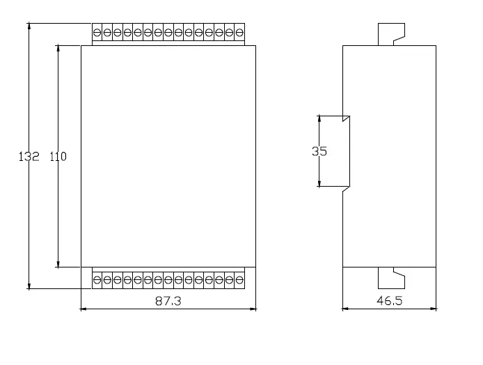
Maximum power consumption 3W - Dimensions : L × H × D =87.3X132X46.5mm (with wiring terminal)
INSTALLATION AND START-UP
The manual you hold in your hands contains information and warnings that the user should respect in order to guarantee a proper operation of all the instrument functions and keep its safety conditions. The instrument must not be powered and used until its definitive assembly is on the cabinet’s door.
Whether the instrument is not used as manufacturer’s specifications, the protection of the instrument can be damaged.
When any protection failure is suspected to exist (for example, it presents external visible damages),the instrument must be immediately powered off. In this case contact a qualified service representative.
Installation
Mounting
Instrument is to be mounted on 35mm Din-rail. Keep all connections inside the cabinet.
Note that with the instrument powered on, the terminals could be dangerous to touch and cover opening actions or elements removal may allow accessing dangerous parts. Therefore, the instrument must not be used until this is completely installed. 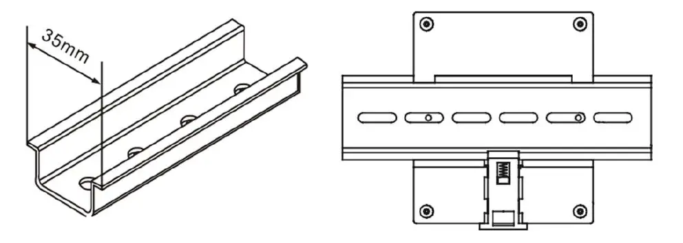
Notes:
Auxiliary power:
MCM400 meter with AUX power input, if not for a special statement, we provide the 85-265VAC/DC power interface for standard products. Please ensure that the auxiliary power match meter access to prevent damage to the product.
Connection terminal of MCM400
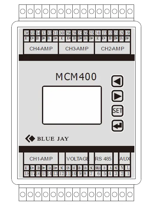
Notes:
The current input pin need to access the CT, and output signal of CT is 0-100mA or 0~0.333V, please confirm your ordering meter types and prepare related CT.
Wiring diagram may be changed due to the special requirements of customers order, please refer the label on the rear part.
If you are or sure or signs unclear please contact:
Blue Jay Technical Support: [email protected]
SETUP PROCEDURE
Key operation
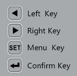
 for screen switch or value increase/decrease
![]() “ for menu enters or exit
“ for menu enters or exit
![]() “ for enter next menu or confirm the change
“ for enter next menu or confirm the change
Show electric parameters
When the MCM400 in monitor screen, user can use keypad switch shows the electrical parameters,
- Press “→” to switch another screen in this channel,
- Press “←” to switch another channel parameter
- Press”
 to switch more details parameter in screen screen roller logic as following:
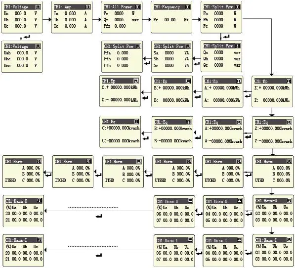
Note:
Energy data is displayed in 8-digit decimal format by default.
As counter increased, the decimal point position will move right, data increased by 10 times, the unit display changing from KWh to MWh.
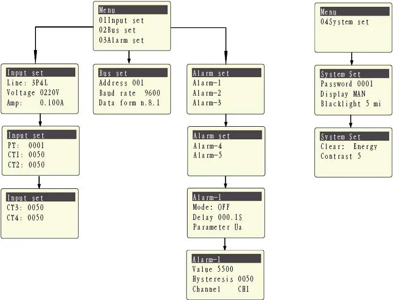
Parameters Setting
The SETUP procedure of the MCM400 is performed by means of several SETUP options. When into the SETUP, use the keyboard to select different options and enter required variables:
Press the key SET can enter the parameter setting. the screen ask access password (Default is 0001), then press ![]() can enter the menu.
can enter the menu.
The operation menu logic as following:
 Notes:
- Clear energy: Customers can write commands through RS485 or through the screen to clear the energy data to 0. Once the secondary side value of the internal memory reaches to 232(4294,967,296), counter automatically reset to 0.
- Clear energy: write command 0x0A0A to register address 3000
Menu Structure
| level 1 | Level 2 | Level 3 | Level 4 | Description |
| Input Setting | Wiring mode | 3P4L/3P3L2CT/3P3 L3CT | input signal network measurement | |
| Rated volt | 220V | Default setting, cannot be modified | ||
| Rated amp | 0.100A(100mA) | Default setting, cannot be modified | ||
| PT ratio | Last time set value | 1~9999 | Default 0001 | |
| CT ratio of CH1 | Last time set value | 1~9999 | Default 0050 | |
| CT ratio of CH2 | Last time set value | 1~9999 | Default 0050 | |
| CT ratio of CH3 | Last time set value | 1~9999 | Default 0050 | |
| CT ratio of CH4 | Last time set value | 1~9999 | Default 0050 | |
| Comm Setting | Address | 1~247 | / | Default 0001 |
| Baud Rate | 2400 / 4800 / 9600 | / | Default is 9600 | |
| Check format | n.8.1 / o.8.1 / e.8.1 | / | Factory default (n.8.1) | |
| Alarm Setting | Alarm_1~5 | Mode | OFF / Upper Limit / Lower Limit | Total three mode |
| Delay | / | Alarm triggered time delay, Default 001.0s | ||
| Parameter | Ua/Ub/Uc/Uab/Ubc… | Alarm triggered parameters | ||
| Value | 0~9999 | Default is 5500,value related to secondary side parameters, unit: Volte – 0.1V; Amp – 0.001A; Active power – 0.1W; Reactive power – 0.1VAR; Power factor – 0.001; Frequency – 0.01HZ; | ||
| hysteresis | 0~9999 | Default is 0050 | ||
| Related channel | CH1-4 | Default CH1 | ||
| System Settings | Password | 0~9999 | / | Reset user password |
| Display | MAN Number 1~9 | / | Manual switching, or automatic switching in 1~9sec | |
| Backlight | 1~5 | / | LCD backlight duration, unit is min, default is 5 | |
| Clear | Energy | / | Clear the record in meter | |
| Contrast | 1~9 | / | LCD display contrast, default is 5 |
Connection for the RS485 BUS
The composition of the RS-485 cabling must be carried out with a meshed screen cable
(minimum 3 wire), diameter of not less than 0.5mm2, with a maximum distance of 1,200 m between the BJ194… and the master unit. This Bus may connect a maximum of 32 BJ194…
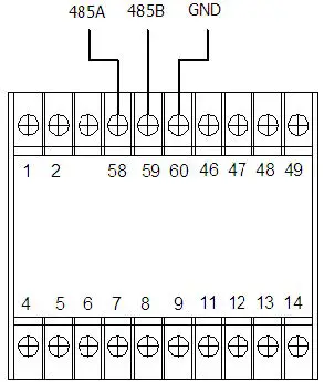 Note:
Note:
- For communication with the master unit, customers can choose the RS-232 to RS-485 converter to use
- Full range of BJ-… meter RS485 PIN number is 58,59,60
- Due to product modifications or custom requirements, the interface pin place may be changed. For details, please refer to product label on the rear board
MODBUS © protocol
Modbus RTU Frame Format:
| Address code | 1 BYTE | Slave device address 1-247 |
| Function code | 1 BYTE | Indicates the function codes like read coils / inputs |
| Data code | 4 BYTE | Starting address, high byte Starting address, low byte Number of registers, high byte Number of registers, low byte |
| Error Check code | 2 BYTE | Cyclical Redundancy Check ( CRC ) |
| Code: | Meaning: | Description: |
| FUNCTION 03/04 | Reading of n Words | This function permits to read all the electrical parameters of the BJ…series. |
| FUNCTION 06 | Write register | Write value in to the relevant register |
Register Address Table
Basic Power Data—Primary Side
| Address | Data | Byte mode | Instruction | |
| 0 | CH1_Ua | float | 2 | Channel_1 Phase to Line Voltage, Unit: V |
| 2 | CH1_Ub | float | 2 | |
| 4 | CH1_Uc | float | 2 | |
| 6 | CH1_Uab | float | 2 | Channel_1 Phase to Phase Voltage, Unit: V |
| 8 | CH1_Ubc | float | 2 | |
| 10 | CH1_Uca | float | 2 | |
| 12 | CH1_Ia | float | 2 | Channel_1 Three phase Current, Unit: A |
| 14 | CH1_Ib | float | 2 | |
| 16 | CH1_Ic | float | 2 | |
| 18 | CH1_Pa | float | 2 | Channel_1 Individual phase active power, Unit: kW |
| 20 | CH1_Pb | float | 2 | |
| 22 | CH1_Pc | float | 2 | |
| 24 | CH1_P∑ | float | 2 | Channel_1 Total active power, Unit: kW |
| 26 | CH1_Qa | float | 2 | Channel_1 Individual phase reactive power, Unit: kVar |
| 28 | CH1_Qb | float | 2 | |
| 30 | CH1_Qc | float | 2 | |
| 32 | CH1_Q∑ | float | 2 | Channel_1 Total reactive power, Unit: kVar |
| 34 | CH1_Sa | float | 2 | Channel_1 Individual apparent power, Unit: kVA |
| 36 | CH1_Sb | float | 2 | |
| 38 | CH1_Sc | float | 2 | |
| 40 | CH1_S∑ | float | 2 | Channel_1 Total apparent power, Unit: kVA |
| 42 | CH1_PFa | float | 2 | Channel_1 Individual power factor, 0~1.000 |
| 44 | CH1_PFb | float | 2 | |
| 46 | CH1_PFc | float | 2 | |
| 48 | CH1_PF∑ | float | 2 | Channel_1 Total power factor, 0~1.000 |
| 50 | CH1_FR | float | 2 | Channel_1 Frequency, Unit:0.01Hz |
| 52 | CH1_EpZ+ | float | 2 | Channel_1 Total positive active energy, Unit: kWh |
| 54 | CH1_EpZ- | float | 2 | Channel_1 Total negative active energy, Unit: kVarh |
| 56 | CH1_EqZ+ | float | 2 | Channel_1 Total positive reactive energy, Unit: kVarh |
| 58 | CH1_EqZ- | float | 2 | Channel_1 Total negative reactive energy, Unit: kWh |
| 60 | CH1_EpA+ | float | 2 | Channel_1 A phase positive active energy, Unit: kWh |
| 62 | CH1_EpA- | float | 2 | Channel_1 A phase negative active energy, Unit: kVarh |
| 64 | CH1_EqA+ | float | 2 | Channel_1 A phase positive reactive energy, |
| Unit: kVarh | ||||
| 66 | CH1_EqA- | float | 2 | Channel_1 A phase negative reactive energy, Unit: kWh |
| 68 | CH1_EpB+ | float | 2 | Channel_1 B phase positive active energy, Unit: kWh |
| 70 | CH1_EpB- | float | 2 | Channel_1 B phase negative active energy, Unit: kVarh |
| 72 | CH1_EqB+ | float | 2 | Channel_1 B phase positive reactive energy, Unit: kVarh |
| 74 | CH1_EqB- | float | 2 | Channel_1 B phase negative reactive energy, Unit: kWh |
| 76 | CH1_EpC+ | float | 2 | Channel_1 C phase positive active energy, Unit: kWh |
| 78 | CH1_EpC- | float | 2 | Channel_1 C phase negative active energy, Unit: kVarh |
| 80 | CH1_EqC+ | float | 2 | Channel_1 C phase positive reactive energy, Unit: kVarh |
| 82 | CH1_EqC- | float | 2 | Channel_1 C phase negative reactive energy, Unit: kWh |
| 100-182 | CH2_ | float | 2 | Channel_2 parameter, structure refer to Channel_1 |
| 200-282 | CH3_parameter | float | 2 | Channel_3 parameter, structure refer to Channel_1 |
| 300-382 | CH4_parameter | float | 2 | Channel_4 parameter, structure refer to Channel_1 |
Meter status data
| Address | Data | Byte mode | Instruction | |
| 1202 | Alarm | int | 1 | 0: without alarm 1: Alarm trigged Bit 0~4 show Alarm_1~5 status |
| 1240 | Wiring mode | Int | 1 | 0: 3P4W 1: 3P3W-2CT 2: 3P3W-3CT |
| 1241 | Voltage range | Int | 1 | Unit: V |
| 1242 | Current range | Int | 1 | Unit: mA |
| 1243 | PT ratio | Int | 1 | Range: 1-9999 |
| 1244 | CT of CH1 | Int | 1 | Range: 1-9999 |
| 1245 | CT of CH2 | Int | 1 | Range: 1-9999 |
| 1246 | CT of CH3 | Int | 1 | Range: 1-9999 |
| 1247 | CT of CH4 | Int | 1 | Range: 1-9999 |
Voltage harmonic (max 21th)
| Address | Data | Byte mode | Instruction | |
| 1300 | THDUa | int | 1 | A-phase Voltage THD, unit 0.1% |
| 1301 | THDUb | int | 1 | B-phase Voltage THD |
| 1302 | THDUc | int | 1 | C-phase Voltage THD |
| 1303 | TOHDUa | int | 1 | A-phase Voltage odd harmonic total distortion, unit 0.1% |
| 1304 | TOHDUb | int | 1 | B-phase Voltage odd harmonic total distortion |
| 1305 | TOHDUc | int | 1 | C-phase Voltage odd harmonic total distortion |
| 1306 | TEHDUa | int | 1 | A-phase Voltage even harmonic total distortion, unit 0.1% |
| 1307 | TEHDUb | int | 1 | B-phase Voltage even harmonic total distortion |
| 1308 | TEHDUc | int | 1 | C-phase Voltage even harmonic total distortion |
| 1320-1339 | HUa | int | 20 | A phase voltage harmonic ratio for 2 to 21th, unit 0.1% |
| 1340-1359 | HUb | int | 20 | B phase voltage harmonic ratio for 2 to 21th |
| 1360-1379 | HUc | int | 20 | C phase voltage harmonic ratio for 2 to 21th |
Current harmonic (max 21th)
| Address | Data | Byte mode | Instruction | |
| 1400 | THDIa1 | int | 1 | Channel_1 A-phase Current THD, unit 0.1% |
| 1401 | THDIb1 | int | 1 | Channel_1 B-phase Current THD |
| 1402 | THDIc1 | int | 1 | Channel_1 C-phase Current THD |
| 1403 | TOHDIa1 | int | 1 | Channel_1 A-phase Current odd harmonic total distortion, unit 0.1% |
| 1404 | TOHDIb1 | int | 1 | Channel_1 B-phase Current odd harmonic total distortion |
| 1405 | TOHDIc1 | int | 1 | Channel_1 C-phase Current odd harmonic total distortion |
| 1406 | TEHDIa1 | int | 1 | Channel_1 A-phase Current even harmonic total distortion, unit 0.1% |
| 1407 | TEHDIb1 | int | 1 | Channel_1 B-phase Current even harmonic total distortion |
| 1408 | TEHDIc1 | int | 1 | Channel_1 C-phase Current even harmonic total distortion |
| 1420-1439 | HIa1 | int | 20 | Channel_1 A phase Current harmonic ratio for 2 to 21th, unit 0.1% |
| 1440-1459 | HIb1 | int | 20 | Channel_1 B phase Current harmonic ratio for 2 to 21th |
| 1460-1479 | Hlc1 | int | 20 | Channel_1 C phase Current harmonic ratio for 2 to 21th |
| 1500-1579 | CH2 Harmonic | int | 20 | Channel_2 harmonic value, structure refer to Channel_1 |
| 1600-1679 | CH3 Harmonic | int | 20 | Channel_3 harmonic value, structure refer to Channel_1 |
| 1700-1779 | CH4 Harmonic | int | 20 | Channel_4 harmonic value, structure refer to Channel_1 |
All installation specification described at the previous chapters named: INSTALLATION AND STARTUP, INSTALLATION MODES and SPECIFICATIONS.
MAINTENANCE
Before any adjustment, replacement, maintenance or repairing operation is carried out; the instrument must be disconnected from any power supply source.
When any protection failure is suspected to exist, the instrument must be immediately put out of service. The instrument’s design allows a quick replacement in case of any failure.
For any inquiry about the instrument performance or any failure
Contact to Blue Jay’s technical service.
Blue Jay – After-sales service
E-mail : [email protected]


