BLUE JAY BJ-MCM1100 Multi-channel Circuit Metering System
Multi-channel Circuit Metering System BJ-MCM1100 User Manual
Version 1.4
The BJ-MCM1100 Multi-channel Circuit Metering System is a device that measures the electrical consumption of multiple channels. This system is designed to provide accurate and reliable measurements for industrial and commercial applications. It is important to read the user manual carefully before operating the system to ensure proper usage and avoid any potential safety hazards.
Installation and Start-up
Before turning on the power supply, make sure that the power supply is within the provisions of the instrument. During installation, ensure that the current input terminal is non-open and voltage input terminals are non-short circuit. The communication terminal (RS232/RS485 or Ethernet) should not be imposed on high pressure. The instrument wiring should be consistent with the internal system settings. When communicating with the PC, instrument communication parameters must be consistent with the PC.
Operation Mode
The BJ-MCM1100 Multi-channel Circuit Metering System has different operation modes, including real-time monitoring and data storage. The system can display measurements for each channel and provide cumulative consumption data as well. Users can easily switch between channels and view data on the panel display.
Safety Considerations
Users must follow all safety guidelines provided in the user manual to prevent accidents and ensure proper usage. It is recommended to periodically inspect the system and perform as needed to ensure optimal performance.
Contact Information:
- Tel: +0086-023-67628702
- Website: www.cqbluejay.com
- Address: 1802, Building 2, No.88, Jianxin East Road, Chongqing, 400020, China
- Email: [email protected]
Read me
When you use BJ-MCM1000 series Multi-channel Circuit Metering system, be sure to read this user manual carefully, and be able to fully understand the implications, the correct guidance of operations in accordance with user manual, which will help you make better use of BJ-MCM1000, and help to solve the various problems at the scene.
- Before the meter turning on the power supply, be sure that the power supply within the provisions of the instrument;
- When installation, the current input terminal must non-open, voltage input terminals must Non-short circuit;
- Communication terminal (RS232/RS485 or Ethernet) is strictly prohibited to impose on high pressure;
- Be sure the instrument wiring consistent with the internal system settings;
- When communicating with the PC, instrument communication parameters must be consistent with the PC.
- Please read this user manual carefully
- Please save this document
SUMMARIZE
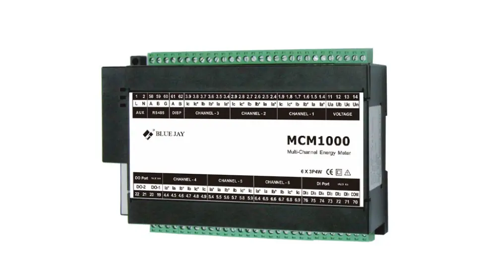
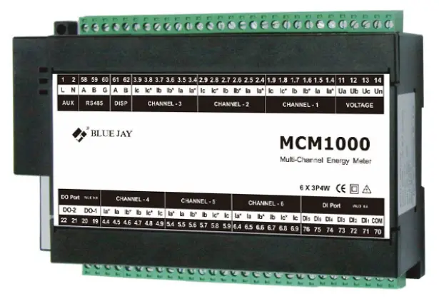
The MCM1000 Series provides a compact and robust metering solution, enable reliable monitoring of building electrical loads with a low installation cost-per-point by combining sub-metering. The unit performs real-time metering, measures energy consumption for max 18 channels circuits for single phase or 6 channel for three phase circuits.
Advanced communications options including Modbus via RS485, I/O communications provide for extensive reliable data exchange. Multiple units can be connected together to meter unlimited number of circuits. The versatility of MCM1000 meters are ideal for multi-tenant or departmental metering applications within office towers, condominiums, apartment buildings, shopping centers and other multi-user environments.
Measurement Function
- Voltage: Line Voltage; Phase Voltage
- Current: Total Current; Current per channel
- Power and Power Factor: Total power Reactive Power, Apparent Power, Power Factor and for per channel
- Frequency: System Frequency
Energy Function
Energy (kWh) measurement meeting international standards, accuracy is Class 1.0
Over/Under Limit Alarming
Users can select parameters and set their set points. An alarm will be triggered when the setpoint is reached. At the same time, sound and light signals could be sent out via relay output. The time and reason of an alarm event will be recorded.
I/O Option
Standard output ports provide energy (kWh) pulse output and time pulse output; optional 6 channel digital inputs (DI) provide pulse counting from water, electricity and gas meter, and monitor switch status; optional 2 channel relay outputs (DO) react upon alarming conditions.
Communication and Network
Supports RS485 communication open protocol: Modbus RTU;
ELECTRICITY METERING
MCM1000 series has two models:
MCM13xx – three phase measurement, max connect 6 channel three phase circuit
MCM11xx -single phase measurement, max connect 18 channel single phase circuit.
The MCM delivers the of parameters listed by RS485 ports, Blue Jay Technology also provide advanced model can connect display unit show visualization information, and do configuration of the MCM device. In the main display area shows 4 power parameters, with other display area show the various parameters and state of meter on each page jump. For more details of measurement parameters please refer to the subsequent for displays introduction.
Metering parameter overall
| Function | Parameter | MCM1110 | MCM1120 | |
|
Real-time Parameter | Voltage | per channel V | ● | ● |
| Current | per channel A | ● | ● | |
| Power | per channel W | ● | ● | |
| Reactive Power | per channel var | ● | ● | |
| Apparent Power | per channel VA | ● | ● | |
| Power Factor | per channel COS | ● | ● | |
| Frequency | per channel Hz | ● | ● | |
| Energy | Active Energy + | per channel | ● | ● |
| Reactive Energy + | per channel | ● | ● | |
| Active Energy – | per channel | ● | ● | |
| Reactive Energy – | per channel | ● | ● | |
| Alarming | Over/Under Limit Alarm | ○ | ● | |
| I/O | 6DI & 2DO | ○ | ● | |
| Display | External LCD display | (RS485 connection) | ● | |
| Communication | RS485 | Modbus-RTU | ● | ● |
Notes: “●” for Standard; “○” for Optional; Blank means Not Available
SPECIFICATIONS
Reference standard:
- Basic electricity: IEC 61557-12:2007
- Active energy: IEC 62053-21:2003
- Reactive energy: IEC 62053-23:2003
Accuracy standards
| Parameter | Accuracy | A phase | B phase | C phase | All |
| Voltage Current Active Power Reactive Power Apparent power Power Factor Active Energy Reactive Energy Frequency | 0.2 0.2 0.5 0.5 0.5 0.5 1 2 0.1 | V1 A1 W1 var1 VA1 PF1 | V2 A2 W2 var2 VA2 PF2 | V3 A3 W3 var3 VA3 PF3 | W |
Input
- Voltage: Rated 40~400V
- Current: Rated 5A (optional 1A)
- Frequency: 45-65Hz
Overload
- Current: 1.2 times rated continuous; 5 seconds for 10 times the rated
- Voltage: 30 seconds for 2 times the rated
Dielectric strength
- IEC/EN 61010-1:2010
- 2kV AC RMS 1 minute, between input / output / case / power supply
EMC Test
| standard | Test voltage | |
| Electrostatic discharge immunity test: | IEC-61000-4-2 level 4 | 8Kv |
| Electrical fast transient burst immunity test | IEC61000-4-4 level 3 | Input 1kV; Power supply 2kV |
| Surge (Shock) immunity test | IEC61000-4-5 level 4 | common mode test voltage 4kV |
Work environment
- Temperature: -15C~ +55C
- Humidity: RH 20%~95% (No condensation)
Storage Conditions
- Temperature: -25C~+70C
- Humidity: RH 20%~95%
Working Power
- AC 80-265V, 45-65Hz, DC 100-350V
- DC 20-60V (Optional)
- Maximum power consumption 6W
- Dimensions L × H × D =180mm×122mm×48mm
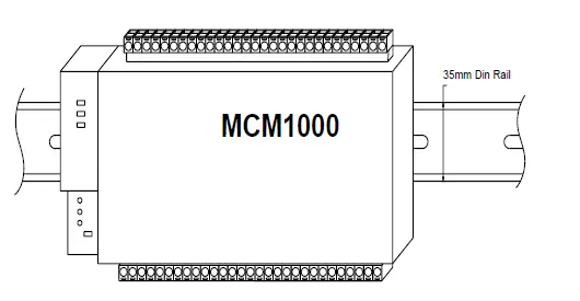
- Installation 35mm Din-Rail
INSTALLATION AND START-UP
The manual you hold in your hand contains information and warnings that the user should respect in order to guarantee a proper operation of all the instrument functions and keep it in safety conditions. The instrument must not be powered on and used until its definitive assembly is on the cabinet’s door.
If the instrument is not used as manufacturer’s specifications, the protection of the instrument will be damaged.
When any protection failure is suspected to exist (for example, it presents external visible damages), the instrument must be immediately powered off. In this case contact a qualified service representative.
Installation
Mounting
This meter is DIN rail mounted, which fits 35 mm standard rails. Keep all connections into the cabinet. Note that with the instrument powered on, the terminals could be dangerous to touch and cover opening actions or elements removal may allow accessing dangerous parts. Therefore, the instrument must not be used until this is completely installed.
Notes:
Input signal: MCM1000 using a separate acquisition calculate for each measurement channel, to ensure consistent in use, for different load forms, it’s a variety of connection mode. Access wire shall be met: the current 2.5 square mm, voltage of 1.5 square millimeters.
- Voltage input:
Input voltage should not exceed the rated input voltage products (100V or 400V), Otherwise, you should use external CT. Suggest 1A fuse be installed in the voltage input side. - Current Input:
Standard input current is 5A, if greater than 5A should use external CT.
When the CT is connected with other instruments, make sure wiring methods be used in series.
Before remove the current input connection, must be sure to disconnect the primary circuit or shorted secondary circuit of CT. In order to facilitate disassembly, please do not connect to CT directly, and the terminal block is suggested. - Please make sure that the input voltage and current corresponding to the same phase sequence, and the same direction; Otherwise, the Values and symbols will be wrong!!(Power and Energy)
The input network configuration of instrument depends on the CT number of the system: in the condition of 2 CT, select the three-phase, three-lines two components; in the condition of 3 CT, select the three-phase, four-lines three component mode. Instrument connection mode, set of the instrument (programming input network NET) should be the same load wiring as measured wiring. Otherwise, the measurement instrument will lead to incorrect voltage or power.
In three-phase three-wire mode, the measurement and shows the line voltage;
In three-phase four-wire mode, the measurement and shows the phase voltage.
Auxiliary power:
MCM1000 Series with universal (AC / DC) power input, if not for a special statement, we provide the 220VAC or 110V/DC power interface for standard products. Instruments limit work power supply: AC: 85-265V / DC: 100~300V, please ensure that the auxiliary power can match with MCM1000 series meter to prevent damage to the product.
- Suggest install 1A fuse in the fire line side.
- For the areas with poor power quality, suggest install lightning surge suppressor and rapid burst suppressor to prevent lightning strikes.
Connection Terminal
Meter Base Terminals:
- Upper row: Digital input, Current Sampling (4-6) Pulse Output, Relay Output
- Lower row: Voltage sampling, Current Sampling (1-3), Display port, Communication, Power Supply
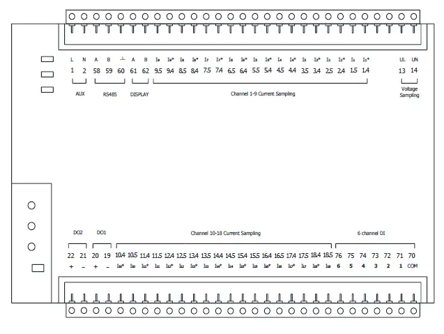
Notes: The terminal pin will change depends on customer order; please refer to the label on the meter!
Typical wiring for 18 channels
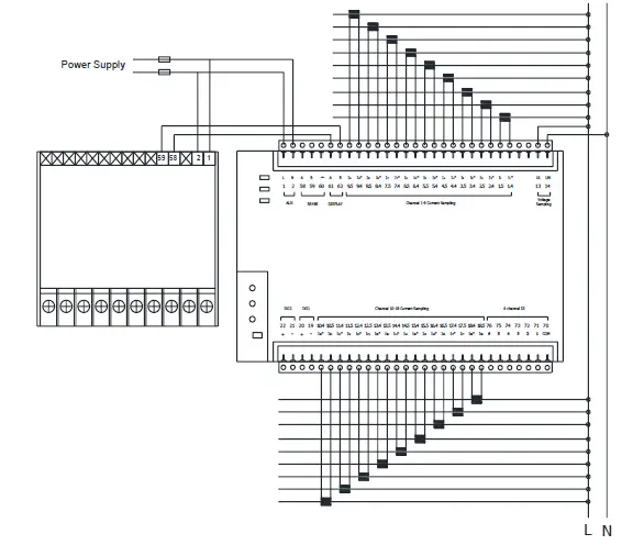
IMPORTANT REMARK!
If power = -0.01 is shown for any of the phases and voltage and current are not zero for this phase, check out following points:
- Assure that A, B and C phases coincide in voltage and current.
- Correct polarity? Reverse the current transformer placed at this phase.
Note: This connection drawing is for reference only; the actual connecting terminal please refer to the label on the rear part.
SCREEN DISPLAY
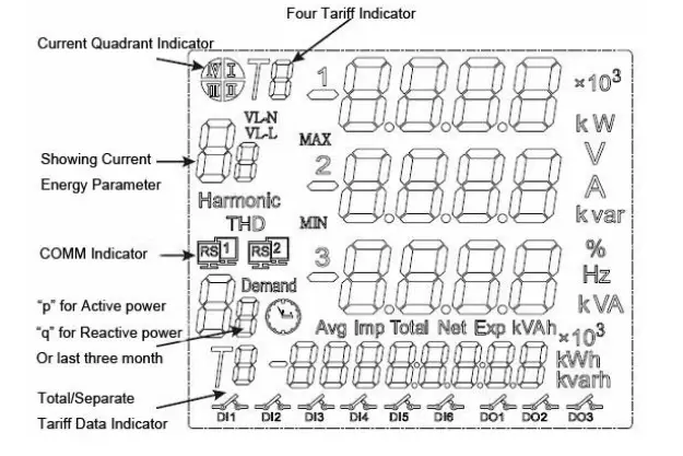
Panel Diagram
MCM1000 optional LCD screen module, connect to RS485 wire to MCM body “DISPLAY” pin, provide electrical data display and on-site configuration.
Note: If your MCM do not have external display unit, please skip chapter 5 and chapter 6, and use RS485 port for operation.
Display unit
connection
Display unit shape and size are same as 194 series power meter. need 85~265VAC/DC AUX power, RS-485 cabling must be carried out with a meshed screen cable (minimum 3 wire), diameter of not less than 0.5mm2, with a maximum distance of 50m between the MCM1000 and the display unit
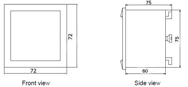
This unit is to be mounted on panel (cut-out 70+0.8 x 70+0.8 mm). Keep all connections into the cabinet.
Note that with the instrument powered on, the terminals could be dangerous to touch and cover opening actions or elements removal may allow accessing dangerous parts. Therefore, the instrument must not be used until this is completely installed.
size of display unit
OPERATION MODE
When the MCM1000 and display unit are powered up, the entire symbol will be on, and the meter starts to self- test. After some seconds, the meter is ready for operation and shows one of the available screens.
![]()
Parameters on display can be switched by pressing key at any moment![]() LCD shown on screen
LCD shown on screen
When the key ![]() is pressed, the screen CURRENT values of each phase are now showing.
is pressed, the screen CURRENT values of each phase are now showing.
Pressing again the key![]() , the screen will show the following parameters successively.
, the screen will show the following parameters successively.
In setting menu,![]() pressing key can move the setting cursor to left;
pressing key can move the setting cursor to left;
Pressing can enter![]() the number 0 ~ 9.
the number 0 ~ 9.
![]()
This key named “SET” key, pressing it can open the programming menu and return to previous menu.
![]()
This key named “Enter” key, pressing this key you can exit it with saving any modification that you might have done, in menu operation press “Enter” key, and user can go to the next menu.
Note:
Press![]() key in normal standby status, and the meter will show different data in main screen:
key in normal standby status, and the meter will show different data in main screen:
In the menu set mode, when changes the parameter and exit setting, the meter will ask to “SAVE”,
press![]() exit without saving
exit without saving
press ![]() save and exit.
save and exit.
Screen 1: Displays the three phase voltage Ua, Ub, Uc;
As shown: Ua = 380.0V; Ub = 380.0V; Uc = 380.0V;
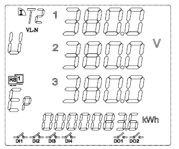
In the bottom character “Ep” show total active energy is 83.6KWh.
In other display area region show the system information:
DI1, DI2, DI3, DI4 in the close state;
DO1, DO2 in the open state;
Communication transceiver normal;
Note: Detail information for each symbol, please refer chapter 5, following sections as same
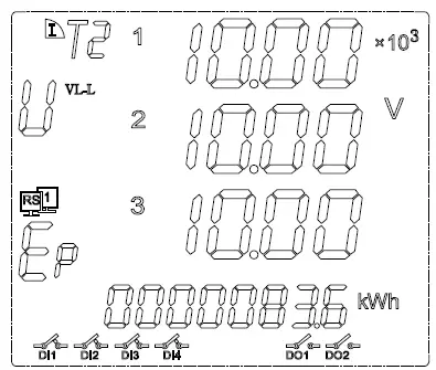
Note: in the high voltage measurement, X103 mean the showing voltage value multiplied by 1000, in the screen diagram mean the voltage is 10X1,000=10,000volt
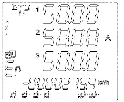
Screen 2: Display the three-phase current Ia, Ib, Ic. In the bottom Ep shows total negative active energy.
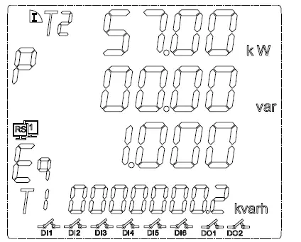
Screen 3: Display the total active power, total reactive power, and total factor. In the bottom “Eq” shows total active energy.
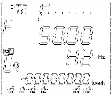
Screen 4: Display the frequency of a phase. In the bottom “Eq” shows total negative reactive energy.
SETUP PROCEDURE
This chart just suits MCM1310 and MCM1110, or client optional display unit, other models please skip this chart to RS485 communication guide, use any series scan programming also can do same setting!!
Once into the SETUP, use the keyboard to select different options and enter required variables:
Input Password
A 4-figure password is required to be entered (in case that in case that the meter will work without permission.)
At normal display mode, press ![]() to enter the programming mode, meter display
to enter the programming mode, meter display
Meter display “
Ask for the password. Press ![]() to input the password number, from “0~9”. Press
to input the password number, from “0~9”. Press![]() to move the cursor. After password switch press
to move the cursor. After password switch press![]() to confirm the input.
to confirm the input.
If password is correct, meter can enter next setting.
Notes: the default password is 0001.
Menu tree quick guide
In the Setup menu, include following 4 parts:
- SYS
- -IN-
- BUS
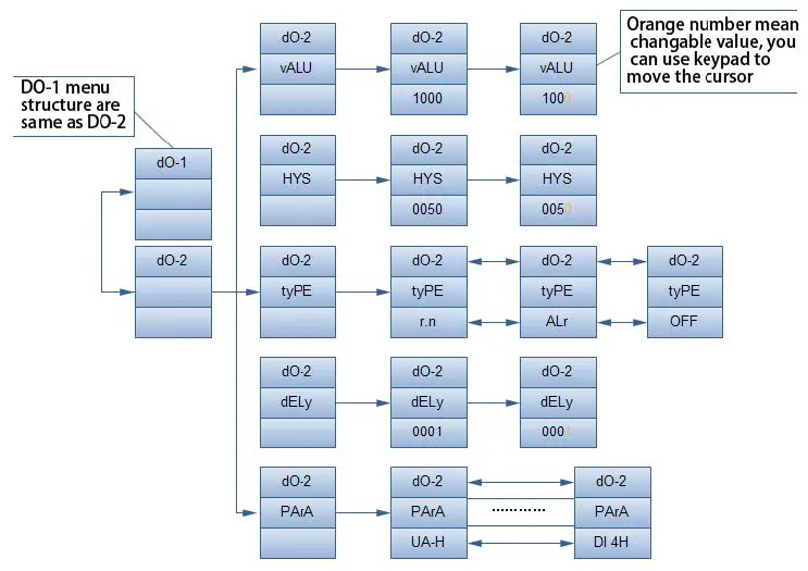
- DO
Sub-menu please refer to following drawing:
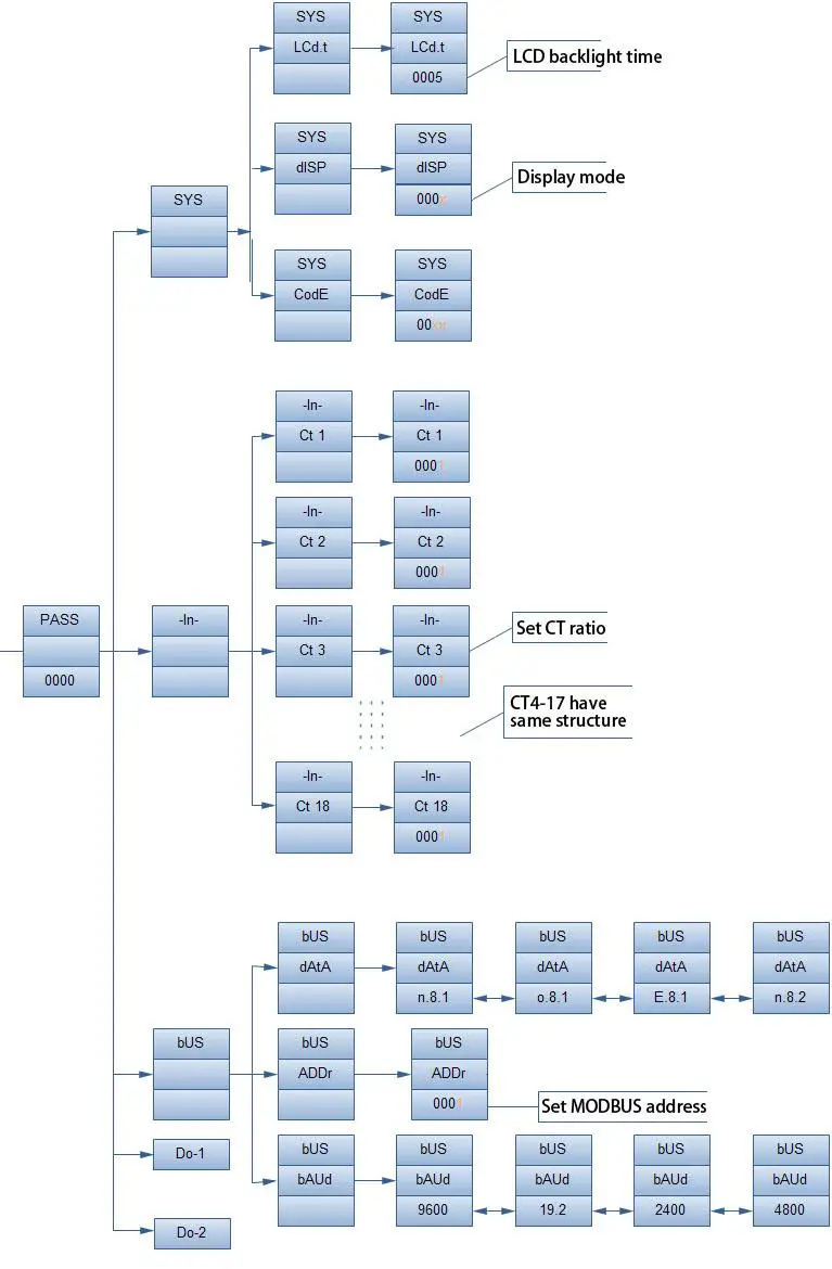
Menu Structure
(Communication Parameters)bUS(Address) ADDR (Digital output setting) DO-1 to DO-2(Output type) TYPE
| level 1 | Level 2 | Level 3 | Description |
| (System setting) SYS | (LCD backlight time) LCd.t | 0000~1000 | Factory default is 0005 |
| (Clear energy counters) CLr.E | Unrecoverable for Clear data | ||
| (Display mode) dISP | 0-99 | 0 for manual switching, 1-99 for X sec auto switch to next screen Factory default is manual | |
| (Change the password) CodE | 0000~9999 | Default is 0001 | |
| (Signal input) – IN- | (Net) Lin.e | N.3.4, N.3.3, N.1 | Select the input signal network measurement |
| (Voltage Range) U.SCL | 100V, 220V, 380V | Select the range of measured voltage signal | |
| (Current Range) I.SCL | 5A and 1A | Select the range of measured current signal | |
| (Voltage transformation ratio) R.PT | 1-9999 | Setting voltage signal transformation ratio = 1 / 2 scale | |
| (Current transformation ratio) R.CT | 1-9999 | Setting current signal transformation ratio = 1 / 2 scale | |
| 1-247 | Instrument address range 1-247 | ||
| (Communication speed) BAUD | 4800~9600 | Default is 4800 | |
| Protocol DATA | o.8.1; e.8.1; n.8.1 | Factory default communication mode for the word (n.8.1) | |
| r.n, Alr, OFF | Default is Alr | ||
| (Set output delay) DELY | 0000~9999 | Default is 0010 | |
| Choose the electrical parameter PArA | I3-H, PS-H…U3- H | Default is I3-H | |
| (Set the alarm value) VALU | 0000~9999 | Default is 0050 | |
| hysteresis value HYS | 4800~9600 | Default is 4800 |
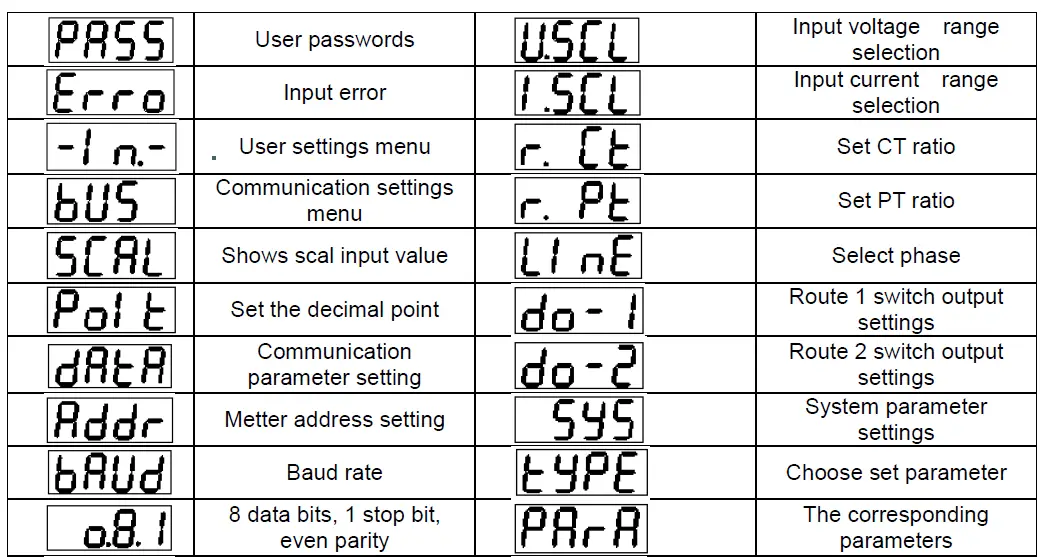
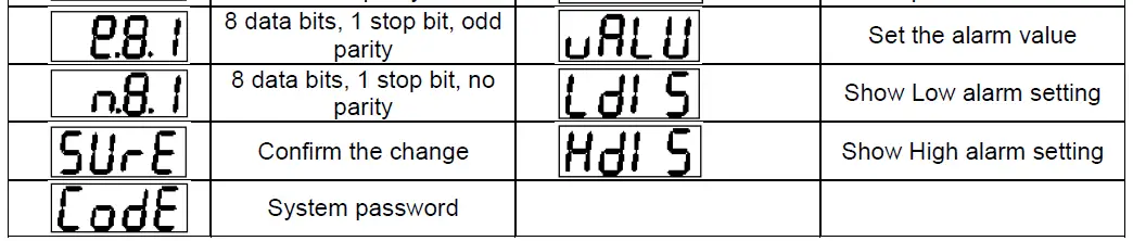
Display Character instructions
COMMUNICATION INTERFACE
Connection for the RS485 BUS
The composition of the RS-485 cabling must be carried out with a meshed screen cable (minimum 3 wire), diameter of not less than 0.5mm2, with a maximum distance of 1,200 meters between the MCM1000 and the master unit. This Bus may connect a maximum of 247 MCM1000
Note:
- Full range of MCM1000 meter RS485 PIN number is 58,59,60
- Due to product modifications or custom requirements, the interface pin place may be change. For details, please refer to product label on the rear board
MODBUS © protocol
Modbus RTU Frame Format:
| Address code | 1 BYTE | Slave device address 1-247 |
| Function code | 1 BYTE | Indicates the function codes like read coils / inputs |
| Data code | 4 BYTE | Starting address, high byte Starting address, low byte Number of registers, high byte Number of registers, low byte |
| Error Check code | 2 BYTE | Cyclical Redundancy Check ( CRC ) |
MODBUS FUNCTIONS
| Code: | Meaning: | Description: |
| FUNCTION 03 | Reading of n Words | This function permits to read all the electrical parameters of the BJ…series. |
| FUNCTION 06 | Write of Registers | Write value in to the relevant register |
Notes: Blue Jay Default disable the write function, if want change configuration via RS485, please contact Blue Jay Sales Team before your order.
Register address table
Basic Power Data—Primary Side
| Address | Data | Byte mode | Instruction | |
| 0 | U_1 | float | 2 | CH_1 Phase to Line Voltage, Unit: V |
| 2 | I_1 | float | 2 | CH_1 Current, Unit: A |
| 4 | P_1 | float | 2 | CH_1 active Power, Unit: KW |
| 6 | Q_1 | float | 2 | CH_1 reactive Power, Unit: Kvar |
| 8 | S_1 | float | 2 | CH_1 apparent Power, Unit: KVA |
| 10 | PF_1 | float | 2 | CH_1 power factor, 0~1.000 |
| 12 | FR_1 | float | 2 | CH_1 frequency, Unit: 0.01Hz |
| 14 | Ep+_1 | float | 2 | CH_1 positive active energy, unit Kwh |
| 16 | Ep-_1 | float | 2 | CH_1 positive reactive energy, unit Kvarh |
| 18 | Eq+_1 | float | 2 | CH_1 negative active energy, unit Kwh |
| 20 | Eq-_1 | float | 2 | CH_1 negative reactive energy, unit Kvarh |
| 30-50 | / | float | 2 | CH_2 parameter, structure same as CH_1 |
| 60-80 | / | float | 2 | CH_3 parameter, structure same as CH_1 |
| 90-110 | / | float | 2 | CH_4 parameter, structure same as CH_1 |
| 120-140 | / | float | 2 | CH_5 parameter, structure same as CH_1 |
| 150-170 | / | float | 2 | CH_6 parameter, structure same as CH_1 |
| 180-200 | / | float | 2 | CH_7 parameter, structure same as CH_1 |
| 210-230 | / | float | 2 | CH_8 parameter, structure same as CH_1 |
| 240-260 | / | float | 2 | CH_9 parameter, structure same as CH_1 |
| 270-290 | / | float | 2 | CH_10 parameter, structure same as CH_1 |
| 300-320 | / | float | 2 | CH_11 parameter, structure same as CH_1 |
| 330-350 | / | float | 2 | CH_12 parameter, structure same as CH_1 |
| 360-380 | / | float | 2 | CH_13 parameter, structure same as CH_1 |
| 390-410 | / | float | 2 | CH_14 parameter, structure same as CH_1 |
| 420-440 | / | float | 2 | CH_15 parameter, structure same as CH_1 |
| 450-470 | / | float | 2 | CH_16 parameter, structure same as CH_1 |
| 480-500 | / | float | 2 | CH_17 parameter, structure same as CH_1 |
| 510-530 | / | float | 2 | CH_18 parameter, structure same as CH_1 |
Float data follow IEEE754, float low bit first, high bit next. (CD AB)
Basic Power Data—Secondary Side
| Address | Data | Byte mode | Instruction | |
| 600 | U_1# | int | 1 | CH_1# Phase to Line Voltage, Unit: 0.1V |
| 601 | I_1# | int | 1 | CH_1# Current, Unit: 0.001A |
| 602 | P_1# | int | 1 | CH_1# active Power, Unit: W |
| 603 | Q_1# | int | 1 | CH_1# reactive Power, Unit: var |
| 604 | S_1# | int | 1 | CH_1# apparent Power, Unit: VA |
| 605 | PF_1# | int | 1 | CH_1# power factor, 0~1.000 |
| 606 | FR_1# | int | 1 | CH_1# frequency, Unit: 0.01Hz |
| 607 | Ep+_1# | int | 1 | CH_1# positive active energy, unit wh |
| 609 | Ep-_1# | int | 1 | CH_1# positive reactive energy, unit varh |
| 611 | Eq+_1# | int | 1 | CH_1# negative active energy, unit wh |
| 613 | Eq-_1# | int | 1 | CH_1# negative reactive energy, unit varh |
| 630-643 | / | int | 1 | CH_2# parameter, structure same as CH_1 |
| 660-673 | / | int | 1 | CH_3# parameter, structure same as CH_1 |
| 690-703 | / | int | 1 | CH_4# parameter, structure same as CH_1 |
| 720-733 | / | int | 1 | CH_5# parameter, structure same as CH_1 |
| 750-763 | / | int | 1 | CH_6# parameter, structure same as CH_1 |
| 780-793 | / | int | 1 | CH_7# parameter, structure same as CH_1 |
| 810-823 | / | int | 1 | CH_8# parameter, structure same as CH_1 |
| 840-853 | / | int | 1 | CH_9# parameter, structure same as CH_1 |
| 870-883 | / | int | 1 | CH_10# parameter, structure same as CH_1 |
| 900-913 | / | int | 1 | CH_11# parameter, structure same as CH_1 |
| 930-943 | / | int | 1 | CH_12# parameter, structure same as CH_1 |
| 960-973 | / | int | 1 | CH_13# parameter, structure same as CH_1 |
| 990- 1003 | / | int | 1 | CH_14# parameter, structure same as CH_1 |
| 1020- 1033 | / | int | 1 | CH_15# parameter, structure same as CH_1 |
| 1050- 1063 | / | int | 1 | CH_16# parameter, structure same as CH_1 |
| 1080- 1093 | / | int | 2 | CH_17# parameter, structure same as CH_1 |
| 1110- 1123 | / | int | 2 | CH_18# parameter, structure same as CH_1 |
Meter status data
| Address | Data | Byte mode | Instruction | |
| 1200 | DO | int | 1 | Digital output: Bit 0~1 show channel 1and channel 2 status 0 for open, 1 for closed |
| 1201 | DI | int | 1 | Digital input: Bit 0~5 show channel 1 to channel 6 status 0 for open, 1 for closed |
R/W parameters
Notes: If do not clear the MCM1000 communication parameter, please shot the “RESET” pin and hole 5sec for recover the communication to default setting
Default setting:
- address: 1
- Baud ratio: 9600
- Data format: n.8.1
| Address | Item | Byte mode | Description | |
| 1210 | Port_1 COMM address | Int | 1 | Range: 1-247 |
| 1211 | Port_1 Baud Ratio | Int | 1 | 0: 2400 1: 4800 2: 9600 3: 19200 |
| 1212 | Port_1 Data format | Int | 1 | 0: n.8.1 1: o.8.1 2: e.8.1 3: n.8.2 |
| 1213 | Port_2 COMM address (for DISPLAY unit) | Int | 1 | Disallowed configuration when work with DISPLAY unit! or will may display error; If done some change, please shot the “RESET” for recover the fault setting |
| 1214 | Port_2 Baud Ratio (for DISPLAY unit) | Int | 1 | |
| 1215 | Port_2 Data format (for DISPLAY unit) | Int | 1 | |
| 1216- 1219 | / | Int | 1 | reversed |
| 1220 | DO1 Mode | In | 1 | 0: Remote 1: Alarm 2: OFF |
| 1221 | DO1 Act delay | Int | 1 | Alarm mode: 0.0-999.9sec Remote mode: 0: Level mode Other value: 0.1-999.9sec (Pulse width) |
| 1222 | DO1 Alarm data | Int | 1 | 0: voltage upper alarm 1: CH_1 current upper alarm 2: CH_2 current upper alarm 3: CH_3 current upper alarm 4: CH_4 current upper alarm 5: CH_5 current upper alarm 6: CH_6 current upper alarm 7: CH_7 current upper alarm 8: CH_8 current upper alarm 9: CH_9 current upper alarm 10: CH_11 current upper alarm 11: CH_11 current upper alarm 12: CH_12 current upper alarm 13: CH_13 current upper alarm 14: CH_14 current upper alarm 15: CH_15 current upper alarm 16: CH_16 current upper alarm 17: CH_17 current upper alarm 18: CH_18 current upper alarm 19: current upper alarm for any channel 20: active power upper alarm for any CHs 21: reactive power upper alarm for any CHs 22: apparent power upper alarm for any CHs 23: power factor upper alarm for any CHs 24: frequency upper alarm for any CHs 25: DI1 close alarm 26: DI2 close alarm 27: DI3 close alarm |
| 28: DI4 close alarm 29: DI5 close alarm 30: DI6 close alarm 31: voltage lower alarm 32: CH_1 current lower alarm 33: CH_2 current lower alarm 34: CH_3 current lower alarm 35: CH_4 current lower alarm 36: CH_5 current lower alarm 37: CH_6 current lower alarm 38: CH_7 current lower alarm 39: CH_8 current lower alarm 40: CH_9 current lower alarm 41: CH_11 current lower alarm 42: CH_11 current lower alarm 43: CH_12 current lower alarm 44: CH_13 current lower alarm 45: CH_14 current lower alarm 46: CH_15 current lower alarm 47: CH_16 current lower alarm 48: CH_17 current lower alarm 49: CH_18 current lower alarm 50: current lower alarm for any channel 51: active power lower alarm for any CHs 52: reactive power lower alarm for any CHs 53: apparent power lower alarm for any CHs 54: power factor lower alarm for any CHs 55: frequency lower alarm for any CHs 56: DI1 open alarm 57: DI2 open alarm 58: DI3 open alarm 59: DI4 open alarm 60: DI5 open alarm 61: DI6 open alarm | ||||
| 1223 | DO1 Alarm value | Int | 1 | Secondary side electrical value |
| 1224 | DO1 HYS | Int | 1 | Hysteresis value |
| 1225 | DO2 mode | Int | 1 | Same as DO1 port |
| 1226 | DO2 Act delay | Int | 1 | |
| 1227 | DO2 Alarm data | Int | 1 | |
| 1228 | DO2 Alarm value | Int | 1 | |
| 1229 | DO2 HYS | Int | 1 | |
| 1230- 1240 | reversed | Int | 1 | / |
| 1241 | Voltage measure range | Int | 1 | 0: 100V 1: 380V |
| 1242 | Current measure range | Int | 1 | 0: 1A 1: 5A |
| 1243 | Voltage transformation ratio | Int | 1 | 1-9999 |
| 1244 | Channel_1 CT ratio | Int | 1 | 1-9999 |
| 1245 | Channel_2 CT ratio | Int | 1 | 1-9999 |
| 1246 | Channel_3 CT ratio | Int | 1 | 1-9999 |
| 1247 | Channel_4 CT ratio | Int | 1 | 1-9999 |
| 1248 | Channel_5 CT ratio | Int | 1 | 1-9999 |
| 1249 | Channel_6 CT ratio | Int | 1 | 1-9999 |
| 1250- 1261 | Channel_7~18 CT ratio | Int | 1 | 1-9999 (only for single phase type) |
| 3000 | Clear energy counter | Int | 1 | Send code: 0x0A0A ( or DCE 2570) |
Note:
- Not all of the data above can be read by RS485, the reading address will be unsuccessful
- The data can be read out depends on your multi-function meter model, please refer to the corresponding product manual before build your software.
- Some software has different definitions of the start bit of register address, there will be offset, please add 1 for the right address. To get more info, please contact technical support [email protected]
Example
Host to Slave inquiry
| Addr | Fun | Data Address (high) | Data Address (low) | Data Number (high) | Data number (low) | CRC16 (low) | CRC16 (high) |
| 0CH | 03H | 00H | 00H | 00H | 06H | C4H | D5H |
PC user ask upload UA, UB, UC, IA, IB, IC
Slave to Host answer
| Addr | Fun | Byte count | Data1 high | Data1 low | Data2 high | Data2 low | Data3 high | Data3 low |
| 0CH | 03H | 0CH | 03H | E8H | 03H | E9H | 03H | E8H |
| Data4 high | Data4 low | Data5 high | Data5 low | Data6 high | Data6 low | CRC16 low | CRC1 6 high | |
| 13H | 84H | 13H | 88H | 13H | 8AH | A6H | D6H |
Show the data:
UA=3E8H (100.0)
UB=3E9H (100.1)
UC=3E7H (99.9)
IA=1384H (4.996)
IB=1388H (5.000)
IC=138AH (5.002)
Notes:
- User can write register data for meter testing and remote control the meter
- When the write is unsuccessful, no return data from the slave, in this addition, user can send write inquiry again
SAFETY CONSIDERATIONS
All installation specification described at the previous chapters named: INSTALLATION AND STARTUP, INSTALLATION MODES and SPECIFICATIONS.
Note that with the instrument powered on, the terminals could be dangerous to touching and cover opening actions or elements removal may allow accessing dangerous parts. This instrument is factory-shipped at proper operation condition.
MAINTENANCE
The MCM1000 does not require any special maintenance. No adjustment, maintenance or repairing action should be done when the instrument is open and powered on, should those actions are essential, high-qualified operators must perform them.
Before any adjustment, replacement, maintenance or repairing operation is carried out, the instrument must be disconnected from any power supply source.
When any protection failure is suspected to exist, the instrument must be immediately put out of service. The instrument’s design allows a quick replacement in case of any failure.
For any inquiry about the instrument performance or any failure, contact to Blue Jay’s technical service.
Blue Jay – After-sales service
Tel: +0086-023-67628702
www.cqbluejay.com
Add: 1802,Building 2,No.88,Jianxin East Road,Chongqing,400020,China
Email: [email protected]


