EBYTE E72-2G4M02S2B CC2640 2.4GHz BLE4.1 SMD
Wireless Module User Manual
Disclaimer
EBYTE reserves all rights to this document and the information contained herein. Products, names, logos and designs described herein may in whole or in part be subject to intellectual property rights. Reproduction, use, modification or disclosure to third parties of this document or any part thereof without the express permission of EBYTE is strictly prohibited.
The information contained herein is provided “as is” and EBYTE assumes no liability for the use of the information. No warranty, either express or implied, is given, including but not limited, with respect to the accuracy, correctness, reliability and fitness for a particular purpose of the information. This document may be revised by EBYTE at any time. For most recent documents, visit www.ebyte.com.
1 General Introduction
1.1 Brief Introduction
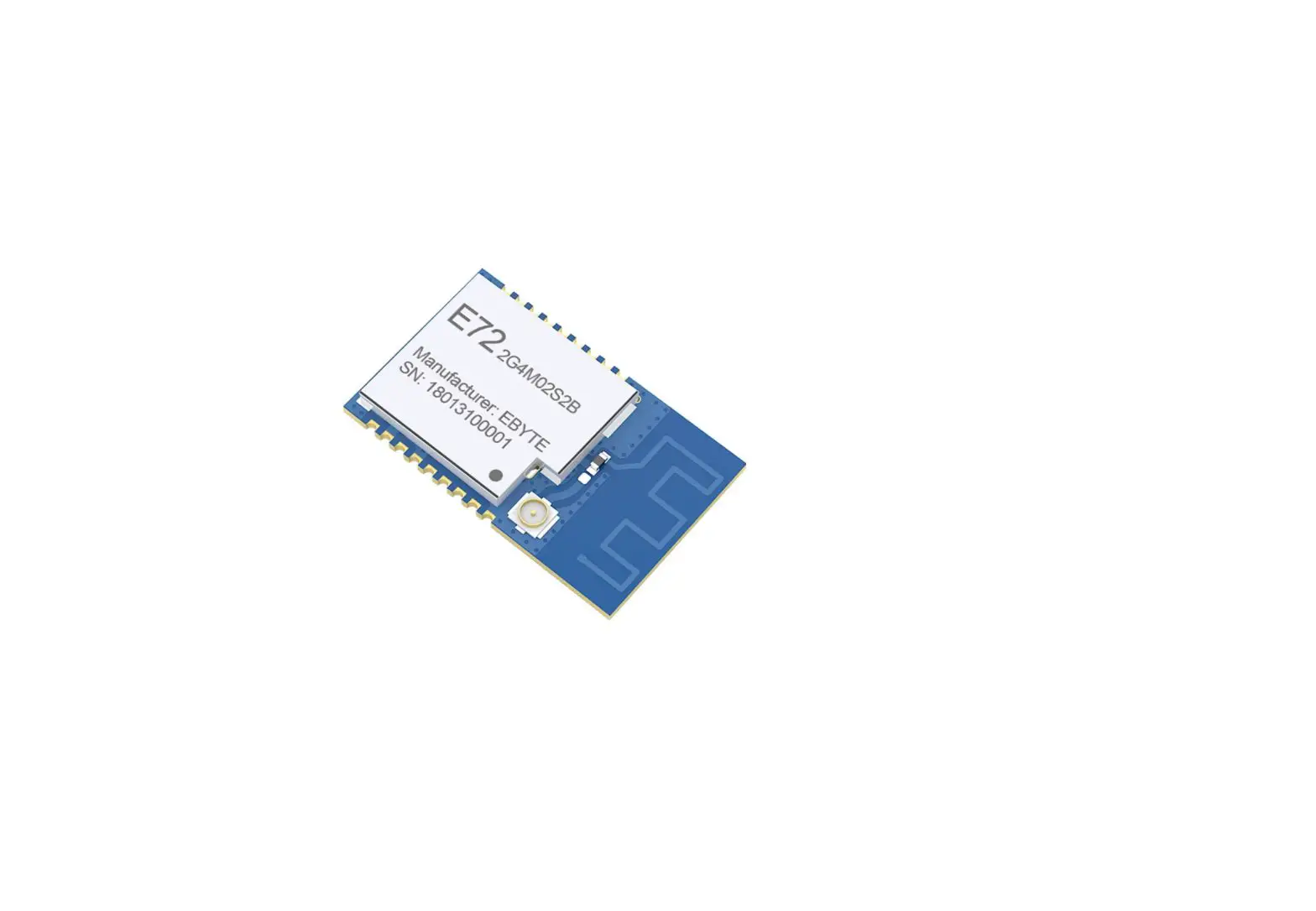
E72-2G4M02S2B is a small-size SMD RF module BLE Bluetooth wireless module independently developed based on CC2640 produced by Texas Instruments (TI)CC2640 chip integrates 128KB intra-system programmable flash and 8KB buffer static RAM (SRAM) and different 2.4GHz wireless communication protocols. It also has a rich set of peripherals. Because of its unique ultra-low-power sensor controller, it’s ideal for connecting external sensors, and it is also suitable for autonomous collection of analog and digital data while the rest of the system is in sleep mode. Thanks to its built-in dual-core low-power processor, users can build a complete system based on their own supporting modules. We used a 24MHz industrial grade high precision low temperature drift active crystal.
The module also supports secondary development. Users can write their own code to achieve the functions.
1.2 Features
- The measured communication distance can reach150/300 m;
- Maximum transmission power of 6mW, software multi-level adjustable;
- Built-in BLE 1protocol stack;
- Built-in 768kHz clock crystal oscillator;
- Support the global license-free ISM 4GHz band;
- Built-in high performance low power Cortex-M3 and Cortex-M0 dual core processor;
- Rich resources,128KB FLASH,28KB RAM;
- Support 8V~3.8V power supply, power supply over 3.3Vcan guarantee the best performance;
- Industrial grade standard design, support -40 ~ 85 °C for working over a long time;
- Support PCB antenna and IPEX interface, users can choose according to
1.3 Application
- Smart homes and industrial sensors;
- Security system, positioning system;
- Wireless remote control, drone;
- Wireless game remote control;
- Health care products;
- Wireless voice, wireless headset;
- Automotive industry
2 Specification and parameter
2.1 limit parameter
| Main parameter | Performance | Remark | |
| Min | Max | ||
| Power supply (V) | 0 | 3.8 | Voltage over 3.6V will cause permanent damage to module |
| Blocking power (dBm) | – | 10 | Chances of burn is slim when modules are used in short distance |
| Operating temperature(℃) | -40 | 85 | – |
2.2 Operating parameter
| Main parameter | Performance | Remark | |||
| Min | Type | Max | |||
| Operating voltage(V) | 1.8 | 3.3 | 3.8 | ≥3.3 V ensures output power | |
| Communication level (V) | 3.3 | For 5V TTL, it may be at risk of burning down | |||
| Operating temperature (℃) | -40 | – | 85 | Industrial grade | |
| Operating frequency(GHz) | 2.402 | – | 2.480 | Support ISM band | |
| Power Consu m-ption | TX current(mA) | 11 | Instant power consumption | ||
| RX current(mA) | 2.0 | ||||
| Sleep current(μA) | 0.2 | Shut down by software | |||
| Max TX power(dBm) | 1.6 | 2.0 | 2.5 | ||
| Receiving sensitivity(dBm) | -96.5 | -97 | -97.5 | Air data rate is 1Mbps | |
| Air data rate(bps) | – | 1M | – | User programming to control | |
| Main parameter | Description | Remark |
| Reference distance | 150/300 m | Test condition: clear and open area, antenna gain: 5dBi, antenna height: 2.5m,air data rate: 250 kbps |
| Crystal Oscillator | 24MHz / 32.768KHz | – |
| Protocol | BLE 4.1 | – |
| Package | SMD | – |
| Interface | 1.27mm | – |
| IC | CC2640F128RSMR | – |
| FLASH | 128 KB | – |
| RAM | 28 KB | – |
| Core | Cortex-M3 + Cortex-M0 | – |
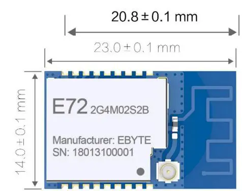
| Size | 14 * 23 mm | – |
| Antenna | PCB / IPEX | 50 ohm impedance |
3 Size and pin definition
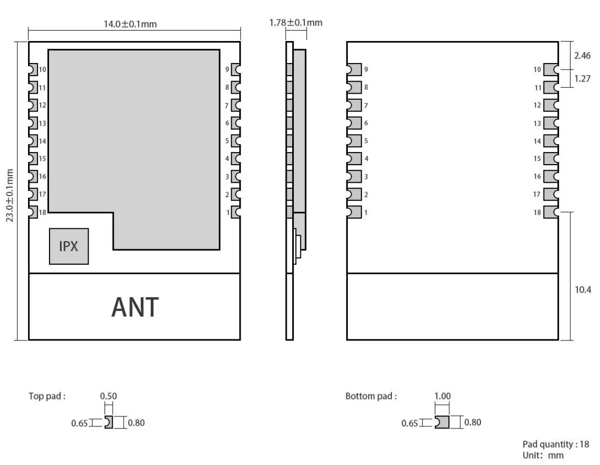
| Pin No. | Item | Direction | Description |
| 1 | GND | – | Ground, connecting to power source referential ground |
| 2 | DIO_0 | Input/output | General IO port, sensor controller (see CC2640 manual for details) |
| 3 | DIO_1 | Input/Output | General IO port, sensor controller (see CC2640 manual for details) |
| 4 | RXD | Input/Output | Serial receive pin |
| 5 | JTAG_TMS | Input/Output | JTAG_TMSC(see CC2640 manual for details) |
| 6 | JTAG_TCK | Input/Output | JTAG_TCKC(see CC2640 manual for details) |
| 7 | TXD | Input/Output | Serial port transmit pin |
| 8 | DIO_4 | Input/Output | High drive IO, JTAG_TDI(see CC2640 manual for details) |
| 9 | GND | – | Ground, connecting to power source referential ground |
| 10 | NRESET | Input | Reset (see CC2640 manual for details) |
| 11 | VDD | – | Power supply: 1.8V ~ 3.8V |
| 12 | DIO_5 | Input/output | SLEEP pin, trigger and wake up |
| 13 | GND | – | Ground, connect to the power reference ground |
| 14 | DIO_6 | Input/output | MRDY pin, trigger serial reception |
| 15 | DIO_7 | Input/output | SRDY pin, wake up external MCU |
| 16 | DIO_8 | Input/output | Connection, output low level |
| 17 | DIO_9 | Input/output | General IO, sensor controller, digital analog (see CC2640 manual for details) |
| 18 | GND | – | Ground electrode, connect to power reference ground |
| ★ Please refer to “CC2640 Datasheet” of TI for pin definition, software drive and protocol★ | |||
4 Circuit design
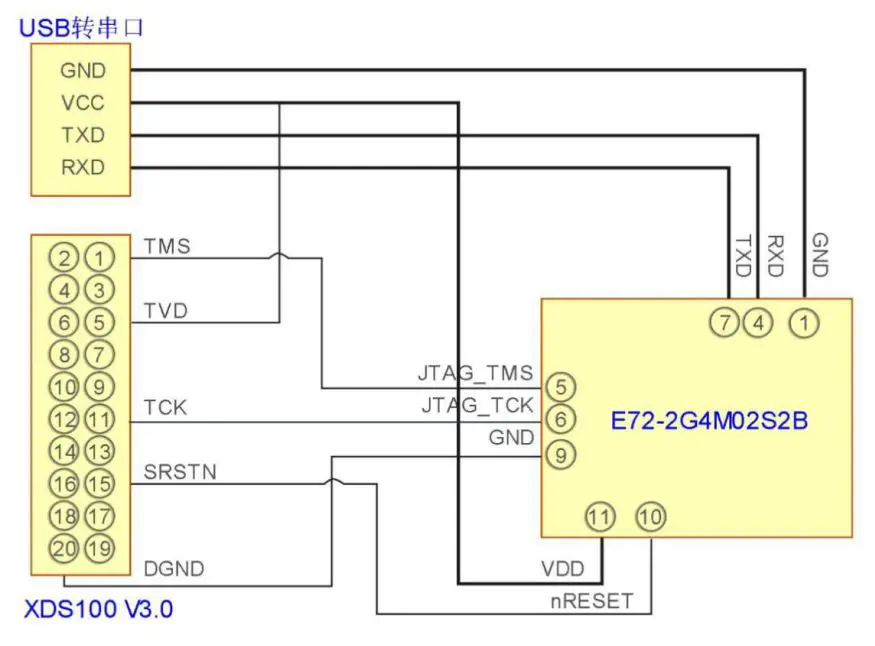
- TMS, TCK, reset, and ground need to be connected between the emulator and the module, and an additional 3.3V power supply is required for the emulator;
- Use USB to UART module to connect with module, module serial port and IO port are multiplexed, users can set according to their own needs;
- Please note that good grounding is When there is a large area of grounding, the power supply ripple is small. Increase the filter capacitor and try to be close to the VCC and GND pins of the module.
5 Operation mode
| No. | Operation mode | Function Description |
|
1 | Low power consumption n | The module enters low power mode after it powers on and the module keeps in advertising state. The serial port stops receiving any data while transparent output function of Bluetooth will not be affected, which means serial output function is still valid in this mode, data received by Bluetooth can output via serial ports. |
|
2 |
Transparent transmission n | In the low power consumption mode, the module enters the state of serial port receiving by pulling down DIO_6 pin. When the Bluetooth is not connected, it keeps in command reception status; When the Bluetooth is connected, it’s in transparent transmission mode, the data sent by the serial port to the Bluetooth module can be sent out via Bluetooth. By inputting character “+++”, the module enters the instruction configuration mode and displays “CMD IN”, meaning to enter the command mode; Inputting the character “+++” again, the module returns to command input mode and displays “CMD OUT”. |
| 3 | Sleep | By giving the DIO_5 pin a low level of at least 300ms, the module goes into sleep mode and again triggers the pin, the module returns to low power mode. |
5.1 Multiple roles
This module can be configured as a multi-role mode through the instruction AT+ROLE=1. In this mode, each module can act as master or slave, one device supports three connections, as shown in figure 1.
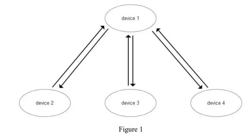
It refers to one master- multi slaves. device 1 can connect device 2, device 3 and device 4 at the same time. The data sent by device 1 can be received by other three devices simultaneously.
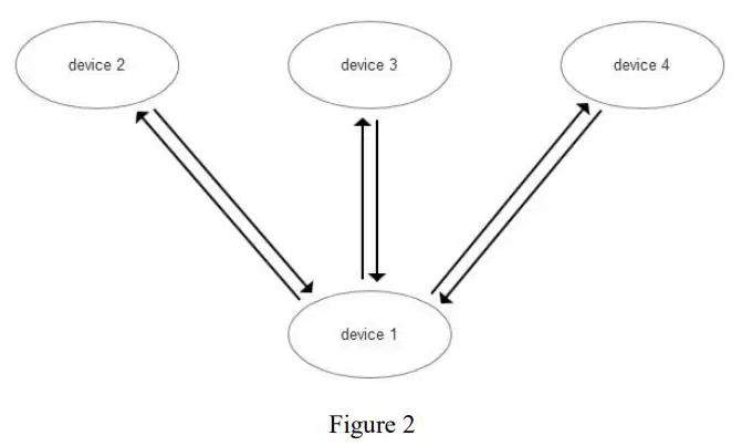
It refers to multi-masters-one slave. Device 1 can connect device 2, device 3 and device 4 at the same time. The data sent by device 1 can be received by other three devices simultaneously, the data sent by device 2, device 3 and device 4 can be received by device 1.
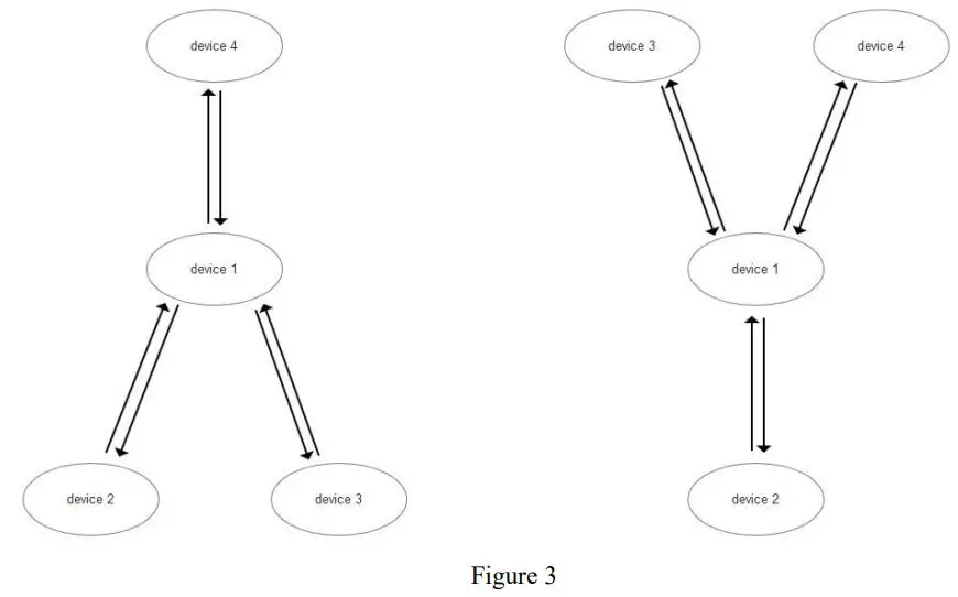
It refers to the topological structure of one master- multi slaves and multi masters- one slave. In the left picture, device 1 can be scanned by device 4 after it connects equipment 2 and equipment 3 at a same time, the connection will be created. The data sent by equipment 1 can be simultaneously received by other three devices, the data sent by equipment 2, equipment 3 and equipment 4 can be received by equipment 1. In the right picture, the device 1 can be scanned by device 3 and device 4 after it connects device 2, the connection will be created. The data sent by device 1 can be simultaneously received by other three devices, the data sent by device 2,device 3 and device 4 can be received by device 1.
5.2 Transparent Continuous Transmission
The module supports transparent continuous transmission, and the baud rate set under continuous transmission can be up to 19200bps. That is to say, the sender’s baud rate is not higher than 19200bps, and the receiving side baud rate is not lower than the baud rate set by the receiver, no matter how large or even continuous data is received by the serial port. Flow, there will be no data loss phenomenon, realizing a transparent transmission in the true sense.
6 Instruction Operation
| No | Command | Description |
| 1 | Factory parameter configuration | See more details in Factory parameter configuration command |
| 2 | AT Instruction set | See more details in 4.11 AT command |
| 3 | Instruction format | All operating instruction formats are in the normal string input mode, no newline, no carriage return, non-hexadecimal For example, query baud rate, the format is AT+UART Set the baud rate in the format of AT + UART = 115200, 8, 1, 0 |
6.1 Command response
| Returned value | Description |
| OK—AT + instruction: | Query response return |
| PARA SET: | Set response return |
| CMD ERROR | Command error |
| RANG ERR | Configuration range error |
| PARA ERR | Parameter configuration error |
| PARITY ERR | Serial parity bit error |
| STOP ERR | Serial stop bit error |
| DATA ERR | Serial data bit error |
| BAUD ERR | Serial baud rate error |
6.2 AT Command
| +++ | Mode switching instruction |
| AT+RESET | Reset instruction |
| AT+FACTORY | Restore default settings |
| AT+VER | Query version information |
| AT+MAC | Query MAC address |
| AT+NAME | Query /Set device’s name |
| AT+UART | Query baud rate |
| AT+ROLE | Query/Set device’s role |
| AT+ADVIN | Query/Set advertising interval |
| AT+CONIN | Query/Set connection interval |
| AT+ADVON | Open advertising |
| AT+ADVOFF | Close advertising |
| AT+TXPWR | Query/Set power |
| AT+RSSI | Acquire the RSSI of connected device |
| AT+DISCONN | Disconnection |
| AT+UUID | Query/Set UUID |
| AT+ADVDATA | Query/Set advertising data |
| AT+IBEACON | Query/Set IBEACON data |
| AT+SCAN | Scan advertising device |
| AT+CONNECT | Connect to specified device |
6.3 Mode switching
| Command | Description | Echo |
| +++ | Mode switching | CMD IN,CMD OUT |
| This command is used to switch to the command mode after the device has been connected, or to enter the transparent transmission from the command mode. The transparent mode enters the command mode to generate the echo CMD IN, and enters the transparent mode from the command mode to generate the echo CMD OUT. | ||
6.4 Reset
| Command | Description | Echo |
| AT+RESET | System Reset | Null |
| After executing this instruction, the module generates a reset operation. | ||
6.5 Restore the default settings
| Command | Description | Echo |
| AT+ FACTORY | Restore the default settings | OK–AT+FACTORY: Factory Mode SUCCESS |
| After executing this command, the module will be restored to factory settings and will be valid after reset. | ||
6.6 Query version information
| Command | Description | Echo |
| AT+ VER | Query version information | OK–AT+VER: HV: V1.0,SV: V1.0 |
| After executing this command, the module will echo the current software and hardware version number. | ||
6.7 Query MAC address
| Command | Description | Echo |
| AT+ MAC | Query MAC address | OK–AT+MAC: 0x98072D8E79DE |
| After executing this instruction, the module will return to display the MAC address. | ||
6.8 Query / Set device’s name
| Command | Description | Echo |
| AT+ NAME | Query/Set device’s name | Example: OK–AT+NAME: CdEbyte MultiRole |
| Execute the command AT+NAME=CdEbyte MultiRole to set the current module name, no more than 20 characters. Return PARA SET: CdEbyte_MultiRole after success. | ||
6.9 Query/Set UART configuration
| Command | Description | Echo |
| AT+UART | Query/Set UART Configuration | Example: OK–AT+UART: 115200,8,1,0 |
| Execute the command AT+UART=115200,8,1,0 to set the current module name. After success, return PARA SET: 115200,8,1,0. The first data represents the baud rate: 1200, 2400, 4800, 9600, 19200, 38400, 57600, 115200, 128000, 230400, 256000, 460800, 921600; The second data represents the data bit: 5,6,7,8; The third data represents the stop bit: 0,1; The fourth data represents the check digit: 0(none),1(even),2(odd)). | ||
6.10 Query/Set device’s role
| Command | Description | Echo |
| AT+ROLE | Query/Set device’s role | Example: OK–AT+ROLE: Normal |
| Execute the command AT+ROLE=0 to set the current module role to normal mode. After successful, return PARA SET: Normal; Execute the command AT+ROLE=1 to set the current module role to multi-role mode. After successful, return to PARA | ||
6.11 Query/Set advertising interval
| Command | Description | Echo |
| AT+ADVIN | Query/Set advertising interval | Example: OK–AT+ADVIN: 160 |
| After executing the AT+ADVIN=160 command, it returns to PARA SET after successful: AT+ADVIN=160. Among them, the broadcast time = set parameter * 0625ms, if set 160, the broadcast gap is 160 * 0625ms = 100ms. Setting range: 12 ~ 16000. | ||
6.12 Query/Set connection interval
| Command | Description | Echo |
| AT+CONIN | Query/Set connection interval | Example: OK–AT+CONIN: 200,200,0,1000 |
| Execute the command AT+CONIN=200,200,0,1000 to set the current module name. After success, return PARA SET: 200,200,0,1000. The first data represents the minimum connection gap: 6 ~ 3200, connection gap time = set parameter * 1.25ms, if the setting parameter is 200, the connection gap time = 200 * 1.25ms = 250ms; The second data represents the maximum connection gap: 6 ~ 3200, the same as the minimum connection gap setting; The third data represents a delayed event: 0 ~ 499; The fourth data represents the connection timeout period: 10~3200. | ||
6.13 Open advertising
| Command | Description | Echo |
| AT+ADVON | Open advertising | Example: OK–AT+ADVON: Advertising… |
| After executing this command, the module will turn on the broadcast. In Normal mode, if this device is connected, the broadcast will not be executed after executing this command. In Multi Role mode, if the number of connected devices of this device reaches 3, the broadcast will not be executed after this command is executed. | ||
6.14 Close advertising
| Command | Description | Echo |
| AT+ADVOFF | Close advertising | Example: OK–AT+ADVOFF: Advert closeting. |
| After executing this command, the module will turn off the broadcast. | ||
6.15 Query/Set power
| Command | Description | Echo |
| AT+TXPWR | Query/Set power | Example: OK–AT+TXPWR: 0dBm |
| Execute the command AT+TXPWR=2dbm to set the transmit power of the current module. After successful, return to PARA SET: AT+TXPWR=2dbm. Power range: 2dbm, 1dbm, 0dbm, -3dbm, -6dbm, -9dbm, -12dbm, -15dbm, -18dbm, -21dbm. | ||
6.16 Acquire the RSSI of connected devices
| Command | Description | Echo |
| AT+RSSI | Acquire the RSSI of connected devices | Example: OK–AT+RSSI: -64dBm |
| After executing this instruction, the module will return the connected device RSSI. This command is valid only after the device has been connected. | ||
6.17 Disconnection
| Command | Description | Echo |
| AT+DISCONN | Disconnection | Example: PARA SET: Connected to: 0 Disconnected! |
| After executing this command, the module will disconnect the device. | ||
6.18 Query/Set UUID
| Command | Description | Echo |
| AT+UUID | Query/Set UUID | Example: OK–AT+UUID: 0,0xFFF0 1,0xFFF1 2,0xFFF2 3,0xFFF3 |
| Execute the command AT+UUID=0, FFF0 sets the current module name, and returns PARA SET after success: AT+UUID=0, FFF0. The first parameter sets the first UUID, which ranges from 0 to 3; The second parameter is the set UUID number. Please refer to the Bluetooth specification protocol to set the corresponding UUID. | ||
6.19 Query/Set advertising data
| Command | Description | Echo |
| AT+ADVDATA | Query/Set advertising data | Example: OK–AT+ADVDATA: 0x0A00010203040506070809 |
| After executing AT+ADVDATA=0A00010203040506070809, the module will return PARA SET: 0x0A00010203040506070809. The above parameter 0A represents the length of the data to be input, and 00010203040506070809 represents the data to be input. The input data is entered in hexadecimal format. For example, 00 stands for 0x00, 01 stands for 0x01, and 02 stands for 0x02. The data length does not exceed 23 bytes. | ||
6.20 Query/Set IBEACON data
| Command | Description | Echo |
| AT+IBEACON | Query/Set IBEACON data | Example: OK–AT+ADVOFF: Advert closeting. |
| After executing AT+IBEACON=, the module will return PARA SET: 0x020106061AFF4C000215B9407F30F5F8466EAFF925556B57FE6D0049000AC5. The character length does not exceed 31 bytes. The parameters under this command should be in accordance with the format specified by Apple’s official IBEACON protocol. | ||
6.21 Scan advertising device
| Command | Description | Echo |
| AT+SCAN | Scan advertising device | Example: OK–AT+SCAN: Discovering with AT_SCAN… Device 1: 0xDE798E2D0798 |
| If a device is broadcasting, a scan to the device’s MAC address will be printed. The broadcast scanned by this instruction must be the same type of broadcast as the device service. If the service number of the module is FFF0, only the device with the service number FFF0 can be scanned, and other service numbers cannot be scanned. | ||
6.22 Connect to specified device
| Command | Description | Echo |
| AT+CONNECT=1 | Connect to specified device | CONNECT OK, |
| After executing this command, the module will return to display the connection success message CONNECT OK. When the connection is successfully established, the IOID_8 pin will be pulled low and when disconnected, DIO_8 will be set high. | ||
7 Basic operation
7.1 Hardware design
- It is recommended to use a DC stabilized power The power supply ripple factor is as small as possible and the module needs to be reliably grounded.
- Please pay attention to the correct connection of the positive and negative poles of the power supply, reverse connection may cause permanent damage to the module.
- Please check the power supply to ensure that between the recommended supply voltage, if exceeding the maximum, the module will be permanently damaged;
- Please check the stability of the power Voltage can not fluctuate greatly and frequently;
- When designing the power supply circuit for the module, it is often recommended to reserve more than 30% of the margin, so the whole machine is beneficial for long-term stable operation;
- The module should be as far away as possible from the power supply, transformers, high-frequency wiring and other parts with large electromagnetic interference;
- Bottom Layer High-frequency digital routing, high-frequency analog routing, and power routing must be avoided under the If it is necessary to pass through the module, assume that the module is soldered to the Top Layer, and the copper is spread on the Top Layer of the module contact part(well grounded), it must be close to the digital part of the module and routed in the Bottom Layer;
- Assuming the module is soldered or placed over the Top Layer, it is wrong to randomly route over the Bottom Layer or other layers, which will affect the module’s spurs and receiving sensitivity to varying degrees;
- It is assumed that there are devices with large electromagnetic interference around the module that will greatly affect the It is recommended to keep them away from the module according to the strength of the interference. If necessary, appropriate isolation and shielding can be done;
- Assume that there are traces with large electromagnetic interference (high-frequency digital, high-frequency analog, power traces) around the module that will greatly affect the performance of the module. It is recommended to stay away from the module according to the strength of the interference.If necessary, appropriate isolation and shielding can be done;
- If the communication line uses a 5V level, a 1k-5.1k resistor must be connected in series (not recommended, there is still a risk of damage);
- Try to stay away from some physical layers such as TTL protocol at 4GHz , for example: USB3.0;
- The mounting structure of antenna has a great influence on the performance of the module. It is necessary to ensure that the antenna is exposed, preferably vertically upward. When the module is mounted inside the case, use a good antenna extension cable to extend the antenna to the outside;
- The antenna must not be installed inside the metal case, which will cause the transmission distance to be greatly
7.2 Programming
- The core of this module is CC2630, its driving method is completely equivalent to CC2630, the user can operate according to the CC2630 chip manual (see CC2630 manual for details);
- It is recommended to use the Code Composer Studio (CCS) Integrated Development Environment (IDE).
8 FAQ
8.1 Communication range is too short
- The communication distance will be affected when obstacle exists;
- Data lose rate will be affected by temperature, humidity and co-channel interference;
- The ground will absorb and reflect wireless radio wave, so the performance will be poor when testing near ground;
- Sea water has great ability in absorbing wireless radio wave, so performance will be poor when testing near the sea;
- The signal will be affected when the antenna is near metal object or put in a metal case;
- Power register was set incorrectly, air data rate is set as too high (the higher the air data rate, the shorter the distance);
- The power supply low voltage under room temperature is lower than recommended value, the lower the voltage, the lower the transmitting power;
- Due to antenna quality or poor matching between antenna and module.
8.2 Module is easy to damage
- Please check the power supply source, ensure it is between the recommended supply voltage, voltage higher than the maximum will damage the module.
- Please check the stability of power source, the voltage cannot fluctuate too
- Please make sure antistatic measure are taken when installing and using, high frequency devices have electrostatic
- Please ensure the humidity is within limited range, some parts are sensitive to
- Please avoid using modules under too high or too low
8.3 BER(Bit Error Rate) is high
- here are co-channel signal interference nearby, please be away from interference sources or modify frequency and channel to avoid interference;
- Poor power supply may cause messy Make sure that the power supply is reliable;
- The extension line and feeder quality are poor or too long, so the bit error rate is
9 Production guidance
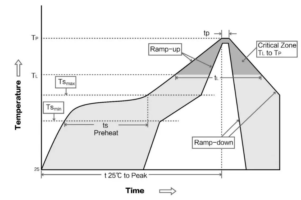
9.1 Reflow soldering temperature
| Profile Feature | Curve characteristics | Sn-Pb Assembly | Pb-Free Assembly |
| Solder Paste | Solder paste | Sn63/Pb37 | Sn96.5/Ag3/Cu0.5 |
| Preheat Temperature min (Tsmin) | Min preheating temp. | 100℃ | 150℃ |
| Preheat temperature max (Tsmax) | Max preheating temp. | 150℃ | 200℃ |
| Preheat Time (Tsmin to Tsmax)(ts) | Preheating time | 60-120 sec | 60-120 sec |
| Average ramp-up rate(Tsmax to Tp) | Average ramp-up rate | 3℃/second max | 3℃/second max |
| Liquidous Temperature (TL) | Liquid phase temp | 183℃ | 217℃ |
| Time(tL)Maintained Above(TL) | Time below liquid phase line | 60-90 sec | 30-90 sec |
| Peak temperature(Tp) | Peak temp | 220-235℃ | 230-250℃ |
| Aveage ramp-down rate(Tp to Tsmax) | Average ramp-down rate | 6℃/second max | 6℃/second max |
| Time 25℃ to peak temperature | Time to peak temperature for 25℃ | 6 minutes max | 8 minutes max |
9.2 Reflow soldering curve
10 E72 series
| Model | IC | Frequency Hz | Tx power dBm | Distance km | Air data rate bps | Package form | Size mm | Antenna |
| E72-2G4M23S1 A | CC2630 | 2.4G | 23 | 1.5 | – | SMD | 17.5 * 33.5 | PCB/IPEX |
| E72-2G4M05S1 A | CC2630 | 2.4G | 5 | 0.5 | – | SMD | 17.5 * 28.7 | PCB/IPEX |
| E72-2G4M02S2 | CC2640 | 2.4G | 2 | 0.3 | BLE 4.1 | SMD | 14 * 23 | PCB/IPEX |
| B | ||||||||
| E72-2G4M05S1 B | CC2640 | 2.4G | 5 | 0.5 | BLE 4.2 | SMD | 17.5 * 28.7 | PCB/IPEX |
11 Antenna recommendation
11.1 Recommendation
The antenna is an important role in the communication process. A good antenna can largely improve the communication system. Therefore, we recommend some antennas for wireless modules with excellent performance and reasonable price.
| Model No. | Type | Frequency Hz | Interface | Gain dBi | Height | Cable | Function feature |
| TX2400-NP-5010 | Flexible Antenna | 2.4G | IPEX | 2 | 50*10mm | – | FPC soft antenna |
| Sucker antenna | 2.4G | SMA-J | 3.5 | 15cm | 150cm | High Gain | |
| Rubber antenna | 2.4G | SMA-J | 3 | 200mm | – | Flexible&ommidirectional | |
| TX2400-JK-11 | Rubber antenna | 2.4G | SMA-J | 2.5 | 110mm | – | Flexible&ommidirectional |
| TX2400-JZ-3 | Rubber antenna | 2.4G | SMA-J | 2 | 30mm | – | Short straight &omnidirectional |
11.2 Antenna selection
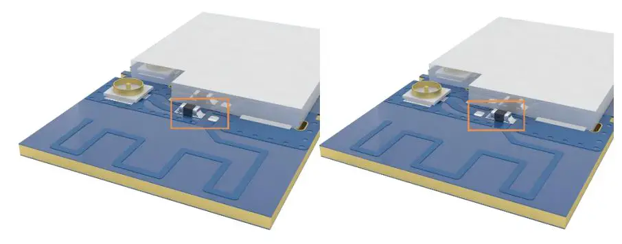
The onboard PCB antenna is enabled by default at the factory, If users enable the IPEX antenna, change the 0R resistor to the above figure (right).and the 0R resistor is shown in the figure above (left).
Revision history
| Version | Date | Description | Issued by |
| 1.00 | 2018/8/30 | Initial version | huaa |
| 1.10 | 2018/11/08 | Model No. split | huaa |
| 1.20 | 2021-2-20 | The image processing | Linson |
About us
Technical support: [email protected]
Documents and RF Setting download link: www.ebyte.com
Thank you for using Ebyte products! Please contact us with any questions or suggestions: [email protected]
Office hotline: 028-61399028 ext. 821 Web: www.ebyte.com
Address: Innovation Center D347, 4# XI-XIN Road, Chengdu, Sichuan, China
![]()


