![]()
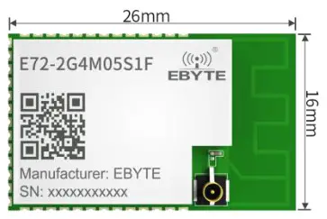
E72-2G4M0551F
CC2652RB Multifunctional SoC Wireless Module
Disclaimer
EBYTE reserves all rights to this document and the information contained herein. Products, names, logos and designs described herein may in whole or in part be subject to intellectual property rights. Reproduction, use, modification or disclosure to third parties of this document or any part thereof without the express permission of EBYTE is strictly prohibited.
The information contained herein is provided “as is” and EBYTE assumes no liability for the use of the information. No warranty, either express or implied, is given, including but not limited, with respect to the accuracy, correctness, reliability, and fitness for a particular purpose of the information. This document may be revised by EBYTE at any time. For most recent documents, visit www.ebyte.com.
Introduction
Brief Introduction
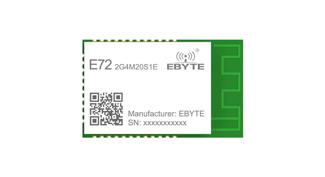
E72-2G4M05S I F is a self-developed, multi-protocol, 2.4G, SMD, wireless SoC module based on CC2652RB from TI. The transmit power is 5dBm. Built-in ARM microcontroller and high-performance wireless transceiver. With an integrated BAW (Bulk Acoustic Wave) resonator to generate a radio frequency carrier, so no external 48MHz crystal is required.
The module leads out all 10 ports of the MCU. Comes with a powerful 48 MHz Arm ® Cortex ® -M4F processor, an internal integrated power amplifier, powerful peripherals, and up to 26 GPIOs, enabling multi-directional development.CC2652RB has the potential to become the best choice of the wireless microcontroller for smart homes, loT transformation, and industrial automation in the future. Since this module is an SoC module, it needs to be programmed by the user before it can be used.
Features
- Powerful 48 MHz Arm 0 Cortex -M4F processor;
- Rich resources, 352KB FLASH, 80KB RAM;
- 1.8-3.8V power supply, over 3.3 V can guarantee the best performance;
- Transmit power 5dBm;
- Under ideal conditions, the communication distance can reach 350m with the external antenna;
- The module contains an external 32.768K low-speed crystal oscillator,
- Industrial grade standard design, support -40 — 85 °C for working over a long time;
- 2 Pin cJTAG and JTAG debugging;
- Support OTA;
- Wireless protocol: Thread, Zigbee, Bluetooth ® 5 Low Energy;
- Receiving sensitivity: —100 dBm for 802.15.4 (2.4 GHz), -102 dBm for Bluetooth 5 Low Energy Coded;
Application
- Building automation solutions
-Building Security System
– Motion Detector, electronic intelligent door lock, door and window sensor, Garage door system, gateway
-HVAC – Thermostat, wireless, sensor, HVAC system controller, gateway
-Fire safety system – smoke and temperature detectors, FACP -Video surveillance – IP webcam -Elevators and escalators – Elevator mains. Elevator and escalator control panel; - Grid infrastructure
-Smart meter – Water meter, gas meter, electricity meter, and heat cost allocator
-Grid communication – Wireless communication, remote sensor applications - Industrial transport – Asset tracking
- Plant automation and control
- Medical
- Electronic Point of Sale (EPOS) – Electronic shelves
- Label (ESL)
Specification and parameter
Limit parameter
| Main parameter | Performance | Remark | |
| Min | Max | ||
| Power supply ( V ) | 0 | 3. | Voltage over 3.8V will cause permanent damage to the module |
| Blocking power ( dBm ) | – | 10 | Chances of burn is slim when modules are used in short distance |
| Operating temperature ( r ) | -40 | N5 | Industrial grade |
Operating parameter
| Main parameter | Performance | Remark | |||
| Min | Type | Max | |||
| Operating voltage (V) | 2. | 3. | 4. | >3.3 V ensures output power | |
| Communication level ( V) | 3. | For 5V TTL, it may be at risk of burning down | |||
| Operating temperature ( °C ) | -40 | – | +85 | Industrial grade | |
| Operating frequency (MHz) | 2400 | – | 2480 | ||
| Power Consumption | TX current ( mA ) | 11 | Instantaneous power consumption @5dBm | ||
| RX current ( mA ) | 8. | ||||
| Max TX power (dBm) | 5. | 5 | 6. | ||
| Receiving sensitivity ( dBm ) | -102 | Bluetooth 5 Low Energy Coded | |||
| Main parameter | Description | Remark |
| Distance | 350m | Test condition: clear and open area, antenna gain: 5dBi, antenna height: 2.5m, air data rate: 150 kbps |
| Distance | 100m | PCB antenna, air data rate 150kbps |
| Crystal frequency | 48MHz/32.768k | 48MHz/low-speed 32.768k |
| Protocol | BLE 5.0 |
| Zigbee Thread | ||
| Package | SMD | |
| Interface | 1.1 mm | Stamp hole |
| IC | CC2652RB 1 FRGZ | |
| FLASH | 352KB | |
| RAM | 8010 | |
| Core | Arm ® Cortex ® -M4F | |
| Size | 26*16mm | |
| Antenna | PCB / IPEX | 5052 impedance |
Size and pin definition
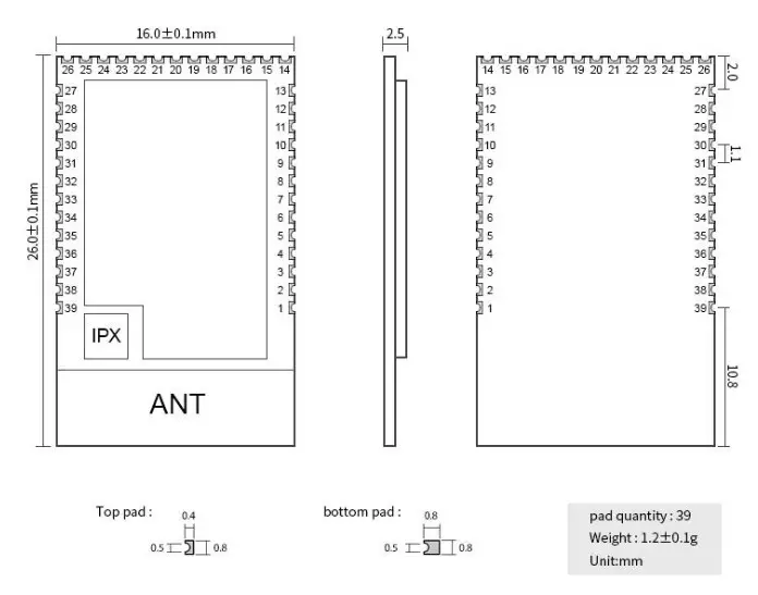
| No. | Item | Direction | Description |
| 1 | DIO 3 | Input/Output | Configurable general 10 port (see CC2652RB I FRGZ manual for details) |
| 2 | DIO 4 | Input/Output | Configurable general 10 port (see CC2652RBIFRGZ manual for details) |
| 3 | DIO 5 | Input/Output | Configurable general 10 port (see CC2652RB I FRGZ manual for details) |
| 4 | DIO 6 | Input/Output | Configurable general 10 port (see CC2652RBIFRGZ manual for details) |
| 5 | DIO 7 | Input/Output | Configurable general 10 port (see CC2652RBIFRGZ manual for details) |
| 6 | DIO 8 | Input/Output | Configurable general I0 port (see CC2652RBIFRGZ manual for details) |
| 7 | DIO_12 | Input/Output | Configurable general I0 port (see CC2652RB1FRGZ manual for details) |
| 8 | DIO_13 | Input/Output | Configurable general I0 port (see CC2652RB1FRGZ manual for details) |
| 9 | DI0_14 | Input/Output | Configurable general I0 port (see CC2652RB IFRGZ manual for details) |
| 10 | DI0_9 | Input/Output | Configurable general I0 port (see CC2652RB I FRGZ manual for details) |
| DIO 10 | Input/Output | Configurable general I0 port (see CC2652RB IFRGZ manual for details) | |
| 12 | DIO 11 | Input/Output | Configurable general I0 port (see CC2652RB IFRGZ manual for details) |
| 13 | DI0_15 | Input/Output | Configurable general 10 port (see CC2652RB IFRGZ manual for details) |
| 14 | JTAG TMSC | Input/Output | JTAG TMSC |
| 15 | JTAG_TCKC | Input | JTAG TCKC |
| 16 | DIO 16 | Input/Output | Configurable general I0 port (see CC2652RB IFRGZ manual for details) |
| 17 | DI0_17 | Input/Output | Configurable general 10 port (see CC2652RB IFRGZ manual for details) |
| Is | DI0_18 | Input/Output | Configurable general 10 port (see CC2652RB I FRGZ manual for details) |
| 19 | DI0_19 | Input/Output | Configurable general 10 port (see CC2652RB IFRGZ manual for details) |
| 20 | DI0_20 | Input/Output | Configurable general 10 port (see CC2652RB I FRGZ manual for details) |
| 21 | DIO 21 | Input/Output | Ground, connected to the power reference ground |
| 22 | GND | Ground, connected to the power reference ground |
| 23 | VCC | Power supply positive, 1.8V – 3.6V | |
| 24 | DI0_22 | Input/Output | Configurable general 10 port (see CC2652RB1 FRGZ manual for details) |
| 25 | RESET_N | Input | Reset, active low (see CC2652RBIFRGZ manual for details) |
| 26 | DI0_23 | Input/Output | Configurable general 10 port (see CC2652RBIFRGZ manual for details) |
| 27 | DIO_24 | Input/Output | Configurable general 10 port (see CC2652RBIFRGZ manual for details) |
| 28 | DIO25 | Input/Output | Configurable general 10 port (see CC2652RBIFRGZ manual for details) |
| 29 | DIO_26 | Input/Output | Configurable general 10 port (see CC2652RBIFRGZ manual for details) |
| 30 | DI0_27 | Input/Output | Configurable general 10 port (see CC2652RBIFRGZ manual for details) |
| 31 | DIO_28 | Input/Output | Configurable general 10 port (see CC2652RBIFRGZ manual for details) |
| 32 | DIO29 | Input/Output | Configurable general 10 port (see CC2652RBIFRGZ manual for details) |
| 33 | DIO 30 | Input/Output | Configurable general I0 port (see CC2652RB I FRGZ manual for details) |
| 34 | X48M-N | 48-MHz crystal oscillator pin 1 (see CC2652RB I FRGZ manual for details) | |
| 35 | X48M-P | 48-MHz crystal oscillator pin 2 (see CC2652RB I FRGZ manual for details) | |
| 36 | DIO 2 | Input/Output | Configurable general I0 port (see CC2652RB I FRGZ manual for details) |
| 37 | DIO 1 | Input/Output | Configurable general I0 port (see CC2652RB I FRGZ manual for details) |
| 38 | DIO 0 | Input/Output | Configurable general I0 port (see CC2652RB I FRGZ manual for details) |
| 39 | GND | – | Ground, connected to the power reference ground |
Development
| No. | Keyword | Notes |
| 1 | 1 Burnprocess | SOC module with GPIO port. The program download uses XDS100 special downloader |
| 2 | Test plate | No matched test plate provide now |
Basic operation
Hardware design
- It is recommended to use a DC stabilized power supply. The power supply ripple factor is as small as possible and the module needs to be reliably grounded;
- Please pay attention to the correct connection of the positive and negative poles of the power supply, reverse connection may cause permanent damage to the module;
- Please check the power supply to ensure that between the recommended supply voltage, if exceeding the maximum, the module will be permanently damaged;
- Please check the stability of the power supply. Voltage can not fluctuate greatly and frequently;
- When designing the power supply circuit for the module, it is often recommended to reserve more than 30% of the margin, so the whole machine is beneficial for long-term stable operation;
- The module should be as far away as possible from the power supply, transformers, high-frequency wiring, and other parts with large electromagnetic interference;
- Bottom Layer High-frequency digital routing, high-frequency analog routing, and power routing must be avoided under the module. If it is necessary to pass through the module, assume that the module is soldered to the Top Layer, and the copper is spread on the Top Layer of the module contact part(well-grounded), it must be close to the digital part of the module and routed in the Bottom Layer;
- Assuming the module is soldered or placed over the Top Layer, it is wrong to randomly route over the Bottom Layer or other layers, which will affect the module’s spurs and receiving sensitivity to varying degrees;
- It is assumed that there are devices with large electromagnetic interference around the module that will greatly affect the performance. It is recommended to keep them away from the module according to the strength of the interference. If necessary, appropriate isolation and shielding can be done;
- Assume that there are traces with large electromagnetic interference (high-frequency digital, high-frequency analog, power traces) around the module that will greatly affect the performance of the module. It is recommended to stay away from the module according to the strength of the interference.lf necessary, appropriate isolation and shielding can be done;
- Try to stay away from some physical layers such as TTL protocol at 2.4GHz, for example, USB3.0;
- The mounting structure of the antenna has a great influence on the performance of the module. It is necessary to ensure that the antenna is exposed, preferably vertically upward. When the module is mounted inside the case, use a good antenna extension cable to extend the antenna to the outside;
- The antenna must not be installed inside the metal case, which will cause the transmission distance to be greatly weakened.
Programming
- The core of this module is CC2630, the user can operate according to the CC2630 chip manual (see CC2630 manual for details).
- Note the chip used by the module DC/DC.
- Burn program: SOC module, with GPIO port, program download using XDS100 dedicated downloader.
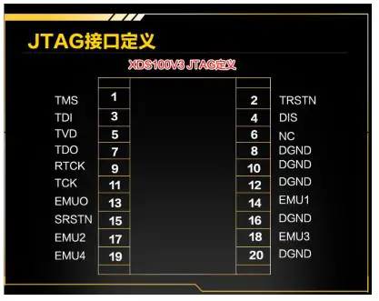
- Program download interface definition:
| E72 PIN | XDS 100 PORT |
| JTAG_TMSC’ | TMS |
| JTAG_TCKC | TCK |
| RESET_N | SUSAN |
| GND | DGND |
| VCC | TVD |
FAQ
The communication range is too short
- The communication distance will be affected when an obstacle exists;
- Data loss rate will be affected by temperature, humidity, and co-channel interference;
- The ground will absorb and reflect wireless radio waves, so the performance will be poor when testing near the ground;
- Seawater has a great ability in absorbing wireless radio waves, so performance will be poor when testing near the sea;
- The signal will be affected when the antenna is near a metal object or put in a metal case;
- Power register was set incorrectly, air data rate is set as too high (the higher the air data rate, the shorter the distance);
- The power supply low voltage under room temperature is lower than the recommended value, the lower the transmitting power;
- Due to antenna quality or poor matching between antenna and module.
The module is easy to damage
- Please check the power supply source, ensure that it is within the recommended supply voltage, a voltage higher than the maximum value, will permanently damage the module;
- Please check the stability of the power source, the voltage cannot fluctuate too much;
- Please make sure antistatic measures are taken when installing and using, high-frequency devices that have electrostatic
- susceptibility;
- Please ensure the humidity is within a limited range, some parts are sensitive to humidity;
- Please avoid using modules under too high or too low temperatures.
BER(Bit Error Rate) is high
- There is co-channel signal interference nearby, please be away from interference sources or modify frequency and channel to avoid interference;
- The poor power supply may cause messy code. Make sure that the power supply is reliable;
- The extension line and feeder quality are poor or too long, so the bit error rate is high.
Production guidance
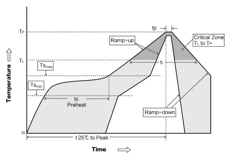
Reflow soldering temperature
| Profile Feature | Sn-Pb Assembly | Pb-Free Assembly |
| Solder Paste | Sn63/Pb37 | Sn96.5/Ag3/Cu0.5 |
| Preheat Temperature min (Tasmin) | 100°C | 150°C |
| Preheat temperature max (Tmax) | 150°C | 200°C |
| Preheat Time (Tasmin to Tsmax)(ts) | 60-120 sec | 60-120 sec |
| Average ramp-up rate(Ts max to Tp) | 3°C/second max | 3°C/second max |
| Liquidous Temperature (TL) | 183°C | 217°C |
| Time(TL)Maintained Above(TL) | 60-90 sec | 30-90 sec |
| Peak temperature(Tp) | 220-235°C | 230-250°C |
| Average ramp-down rate(Tp to Tsmax) | 6°C/second max | 6°C/second max |
| Time 25°C to peak temperature | 6 minutes max | 8 minutes max |
Reflow soldering curve
E72 series
| Model No. | IC | Frequency | Tx power | Distance | Size | Protocol | Communication interface |
| Hz | dBm | km | mm | ||||
| E72-2G4M05S IA | CC2630 | 2.4G | 5 | 0.5 | I 7.5*28.7 | ZigBee | I/O |
| E72-2G4M23S I A | CC2630 | 2.4G | 23 | 2. | I 7.5*33.5 | ZigBee | I/O |
| E72-2G4M05S1 B | CC2640 | 2.4G | 5 | 0.5 | I 7.5*28.7 | BLE 4.2 | I/O |
| E72-2G4MO2S2B | CC2640 | 2.4G | 2 | 0.3 | 14*23 | BLE 4.2 | TTL |
| E72-2G4M2OS I E | CC2652P | 2.4G | 20 | 0.7 | 28.7* I 7.5mm | Multi-protocol | TTL |
Antenna recommendation
Recommendation
The antenna is an important role in the communication process. A good antenna can largely improve the communication system. Therefore, we recommend some antennas for wireless modules with excellent performance and reasonable prices.
| Model No. | Type | Frequency | Gain | Size | Cable | Interface | Features |
| Hz | dBi | mm | cm | ||||
| TX2400-NP-5010 | Flexible antenna | 2.4G | 2.0 | 10\50 | IPEX | FPC soft antenna | |
| TX2400-JZ-3 | Rubber antenna | 2.4G | 2.0 | 30 | – | SMA-J | Short straight &omnidirectional |
| TX2400-JZ-5 | Rubber antenna | 2.4G | 2.0 | 50 | – | SMA-J | Short straight &omnidirectional |
| TX2400-JW-5 | Rubber antenna | 2.4G | 2.0 | 50 | – | SMA-J | Fixed bending, omnidirectional |
| TX2400-JK- II | Rubber antenna | 2.4G | 3. | 110 | – | SMA-J | Bendable, omnidirectional |
| TX2400-JK-20 | Rubber antenna | 2.4G | 3.0 | 200 | – | SMA-J | Bendable, omnidirectional |
| TX2400-XPL-150 | Sucker antenna | 2.4G | 4. | 150 | 150 | SMA-J | Small sucker antenna, cost performance |
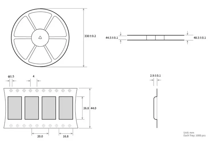
Bulk packing
Revision history
| Ver. | Date | Describe | Staff |
| 1.0 | 2020-12-1 | Initial version | Linson |
About us
Technical support: [email protected]
Documents and RF Setting download link: www.ebyte.com
Thank you for using Ebyte products! Please contact us with any questions or suggestions: [email protected]
Phone: +86 028-61399028
Web: www.ebyte.com
Address: 135 Mould Park, 199# Xiqu Ave, High-tech District, Sichuan, China

Copyright ©2012 – 2021, Chengdu Ebyte Electronic Technology Co., Ltd.


