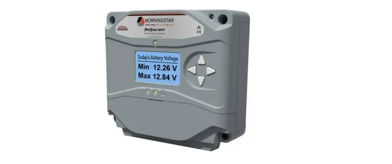
MORNINGSTAR ProStar Solar Charging System Controller
Safety Information
Warning: Shock Hazard
The ProStar Gen3 controller must be installed by a qualified technician in accordance with the electrical regulations of the country of installation.
Warning: Shock Hazard
This unit is not provided with a GFDI device. This charge controller must be used with an external GFDI device as required by Article 690 of the National Electrical Code for the installation location.
IMPORTANT: READ the ProStar Gen 3 Installation Manual for safety and regulatory information, instructions on configuration and operation, and warranty information.
Warranty Registration: https://www.morningstarcorp.com/product‐registration/
In the box:
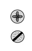
Tools Required:
- #2 Philips Screwdriver
- 3/16 (5 mm) & 3/32″ (2.5 mm) Flathead Screwdriver

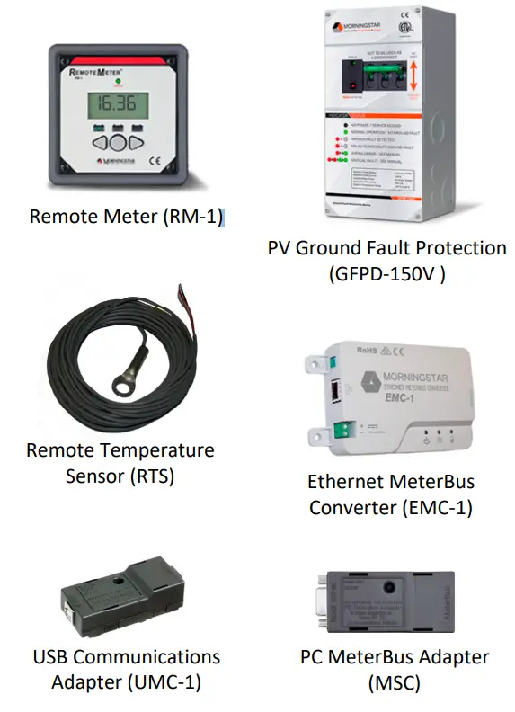
Optional Accessories
Caution: Equipment Damage
Do not expose the ProStar CC to weather. Locate in a dry, protected area to prevent equipment damage. Ensure the minimum clearance requirements are followed to provide adequate ventilation and prevent the unit from overheating.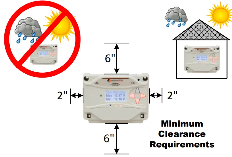
Mounting
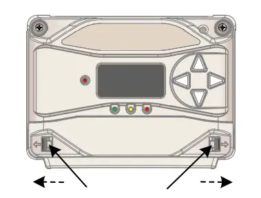
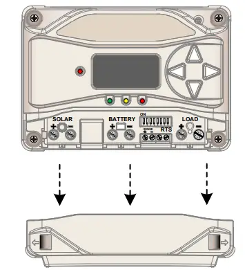
- Push tabs outward to release the terminal cover.

- Pull the terminal cover forward to remove it.

- Tighten the 4 self‐tapping screws just enough to hold the ProStar in place.

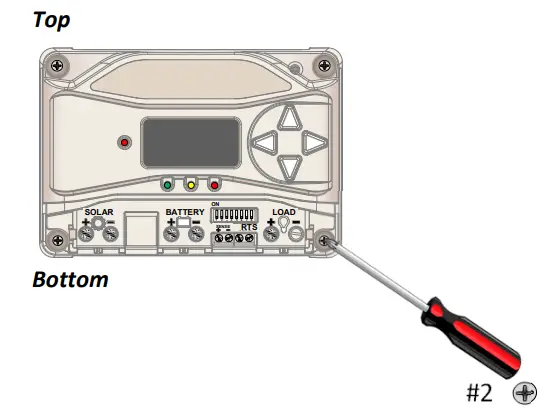
IMPORTANT: Do NOT over tighten.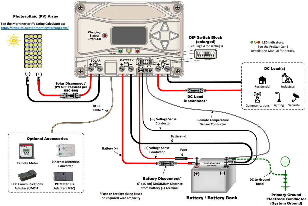
| Wiring and Torque Requirements | |||
| Component | Wire Size | Tool Required | Torque (Max) |
| Power Terminals | 2.5 ‐ 16 mm2 / #14 ‐ 6 AWG | 3/16″(5 mm) Flathead Screwdriver | 35 in‐lbs. (3.9 Nm) |
| Battery Voltage Sense | 0.25 ‐ 1.0 mm2 / #24 ‐ 16 AWG | 3/32″ (2.5 mm) Flathead Screwdriver | 5 in‐lbs. (0.56 Nm) |
| Remote Temperature Sensor | (included) | 3/32″ (2.5 mm) Flathead Screwdriver | 5 in‐lbs. (0.56 Nm) |
| Mounting Screws | ‐‐‐ | #2 Philips Screwdriver | 5 in‐lbs. (0.56 Nm) |
| LEGEND |
| Negative (–) |
| Positive (+) |
| Ground |
Specifications
| PS‐15/PS‐15M | PS‐30/PS‐30M | |
| Nominal Battery Voltage | 12/24 V | 12/24 V |
| Max. PV Open‐Circuit Voltage | 30/60 V | 30/60 V |
| Maximum Input Current | 15 A | 30 A |
| Rated Load Current | 15 A | 30 A |
Operational Configuration
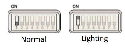
Switch 1: Load/Lighting
| Mode | Switch 1 |
| Normal | OFF |
| Lighting | ON |
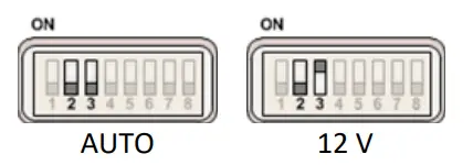
Switches 2 & 3: System Voltage
| System Voltage | Switch 2 | Switch 3 |
| Auto | OFF | OFF |
| 12 | OFF | ON |
| 24 | ON | OFF |
Switches 4, 5, & 6: Battery Type Selection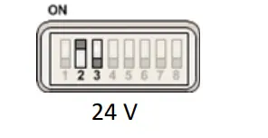 NOTE: The ProStar Gen3 can be programmed to accommodate a wide range of charging parameters. Consult the battery manufacturer for optimal battery charging settings.
To Change Settings:
- On metered models, use the interface on the meter or use the software available at https://www.morningstarcorp.com/msview/.
- On non‐metered models, use the software available at https://www.morningstarcorp.com/msview/.
See the ProStar Installation, Operations, and Maintenance Manual for additional information/guidance.
“Sealed” battery types include Gel and AGM Batteries
Lithium‐ion and some other battery types require custom programming. Morningstar provides downloadable settings for selected battery manufacturers here: https://www.morningstarcorp.com/energy‐storage‐partner‐program/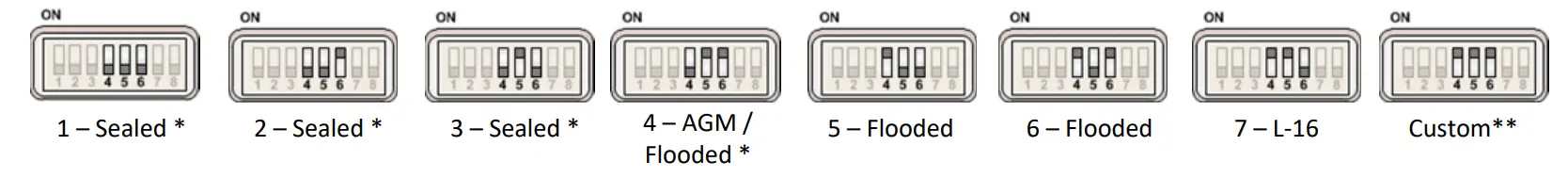
| Shared Settings | Set Point |
| Absorption Extension Voltage | 12.50 Volts |
| Absorption Extension Time | Absorption Time +30 minutes |
| Float Exit Time‐Out | 30 minutes |
| Shared Settings | Set Point |
| Float Cancel Voltage | 12.10 Volts |
| Equalize Time‐Out | Equalize Time +60 minutes |
| Temperature Compensation Co‐Efficient | –30 millivolts / °C / 12 Volts |
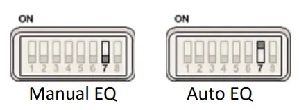
Switch 7: Battery Equalization
| Mode | Switch 7 |
| Manual Equalization | OFF |
| Auto‐Equalization | ON |
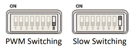
Switch 8: Current Switching
| Mode | Switch 8 |
| PWM Switching | OFF |
| Slow Switching | ON |
Contact Information:
Technical Support: Support.morningstarcorp.com Phone: 1‐215‐321‐4457


