![]()
GS-MPPT-100M-200V Gen Star Solar Charging System Controller
User Guide
INCLUDES: Charge controller; Remote Temperature Sensor (RTS); SD card inside SD card holder; (1) one-meter MS-CAN Cable; (3) ferrite cores; mounting template; (4)- #10 mounting screws
Use following URL to register Morningstar Gen Star MPPT: https://www.morningstarcorp.com/product-registration
IMPORTANT SAFETY INFORMATION:
![]() WARNING: Shock Hazard
WARNING: Shock Hazard
The Morningstar Gen Star MPPT must be installed by a qualified technician in accordance with the electrical regulations of the installation location.![]() WARNING: Shock Hazard
WARNING: Shock Hazard
This unit is not provided with a GFDI device. This charge controller must be used with an external GFDI device as required by Article 690 of the U.S. National Electrical Code and depending on the installation location. CAUTION: This guide must be used with the full product manual that includes important information. Read the Gen Star product manual for all specifications, safety, regulatory and warranty information, and for all required instructions, installation procedures, configuration, and operation details.
![]() Contact Information:
Contact Information:
www.morningstarcorp.com
Phone: 1-215-321-4457
OPTIONAL ACCESSORIES:
See product manuals at www.morningstarcorp.com/support/library/
Ready Relay (RB-Relay-1)
The Ready Relay is an expansion block that adds AC or DC relay dry contact hardware functionality and firmware control and logic to the Morningstar Gen Star MPPT charge controller.
Ready Shunt (RB-Shunt-1)
The Ready Shunt is an expansion block designed to display measured branch currents, count Amp-hours for those branches, and allow net maximum charge current into a battery, but not exceeding the battery’s maximum charging rate.
Ready BMS (RB-BMS-1)
The Ready BMS provides simple visibility of battery performance, hands-free settings and optimized battery control. Through the Ready BMS, the Gen Star MPPT will report any data variable contained in the battery BMS.
| SPECIFICATIONS: | GS-MPPT-60 | GS-MPPT-80 | GS-MPPT-100 |
| Nominal Battery Voltage | 12-24-48V | 12-24-48V | 12-24-48V |
| Maximum PV Open- circuit Voltage | 200V | 200V | 200V |
| Nominal Maximum | 800-1600- | 1075-2150- | 1350-2700- |
| Output Power | 3200W | 4300W | 5400W |
| Maximum Recommended PV Input1 | 1200-2400- 4800W | 1600-3200- 6400W | 2000-4000- 8000W |
| Max. Battery Charging Current | 60A | 80A | 100A |
| Rated Load Current | 30A | 30A | 30A |
¹150% of Nominal Maximum Output Power
| WIRE SIZE RANGES and TORQUE REQUIREMENTS | ||
| Connection Point | Wire Size | Max. Torque |
| Power Terminals | #8-1/0 AWG (8.4 – 53.4 mm2) | 100 in-lb (11.3 N-m) |
| Load Terminals | #14-6 AWG (2.1 – 13.3 mm2) | 35 in-lb (4.0 N-m) |
| Equipment Grounding | #14-#2 AWG | 50 in-lb |
| Terminal | (2.1 – 33.6 mm2) | (5.6 N-m) |
| Battery Voltage Sense Terminals | #24-16 AWG (0.2 – 1.3 mm2) | 5 in-lb (0.56 N-m) |
| Remote Temperature Sensor | INCLUDED | 5 in-lb (0.56 N-m) |
INSTALLATION SAFETY:
![]() WARNING: Shock Hazard Verify that the solar, load and battery breakers and/or disconnects remain open (disconnected) until after all of the system wiring has been completed.
WARNING: Shock Hazard Verify that the solar, load and battery breakers and/or disconnects remain open (disconnected) until after all of the system wiring has been completed.
![]() WARNING: Risk Of Electrical Shock. NO POWER OR ACCESSORY
WARNING: Risk Of Electrical Shock. NO POWER OR ACCESSORY
TERMINALS ARE ELECTRICALLY ISOLATED FROM DC INPUT, AND MAY BE ENERGIZED WITH HAZARDOUS SOLAR VOLTAGE. UNDER CERTAIN FAULT CONDITIONS, BATTERY COULD BECOME OVER-CHARGED. TEST BETWEEN ALL TERMINALS AND GROUND BEFORE TOUCHING.
![]() WARNING: Equipment Damage or Risk of Explosion
WARNING: Equipment Damage or Risk of Explosion
Never install the Gen Star MPPT in an enclosure with vented/flooded batteries. Battery fumes are flammable and will corrode and destroy the Gen Star MPPT circuits.
![]() CAUTION: Equipment Damage
CAUTION: Equipment Damage
Power UP Sequence – refer to manual’s LED Indications Section for full details:
- Connect Battery/Battery Bank.
- Connect Solar.
Power DOWN Sequence:
- Disconnect Solar.
- Disconnect Battery/Battery Bank.
![]() CAUTION: Equipment Damage
CAUTION: Equipment Damage
Ensure sufficient ventilation – see clearance illustration on p. 3 – and do not install in a sealed enclosure. Improper ventilation will result in over-heating and a decreased product lifetime.
FULL MANUAL INSTRUCTIONS:
 https://www.morningstarcorp.com/wp-content/uploads/operation-manual-genstar-mppt-en.pdf
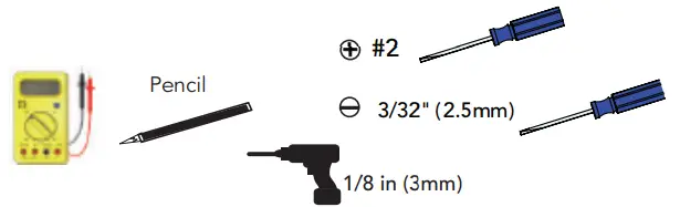
TOOLS REQUIRED:
MOUNTING:

Choose an indoor mounting location, with no exposure to sun or water. When mounting, allow for proper air flow, as seen in upper-right illustration.
Use mounting template to mark, and drill (3)-1/8 in. screw hole locations. Drive top screw head to 1/4 in. from flush with wall. Hang keyhole slot on hanging screw head – see lower-right illustration. Drive top screw head and (2) lower screw heads flush with mounting brackets.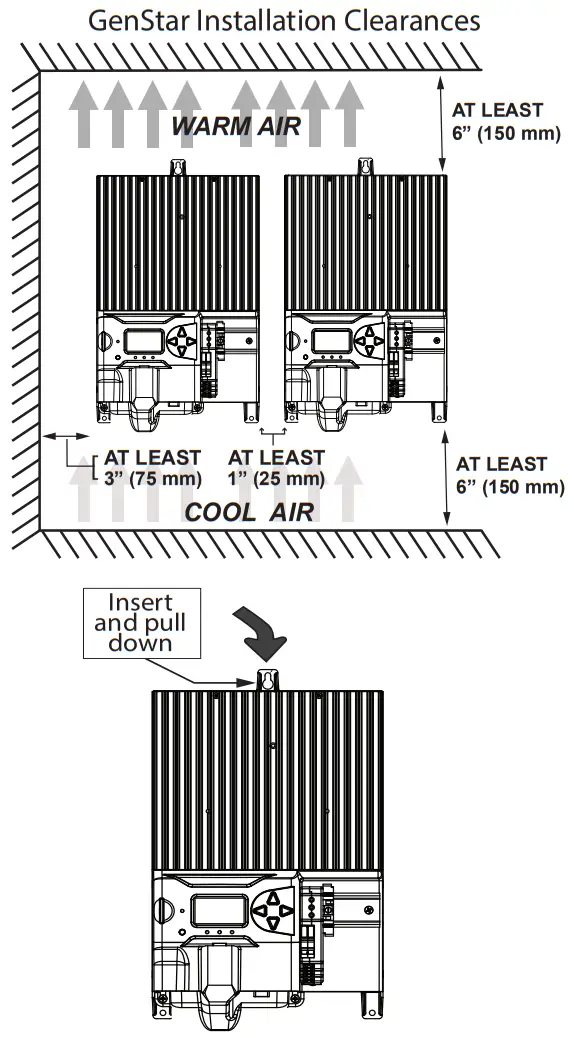
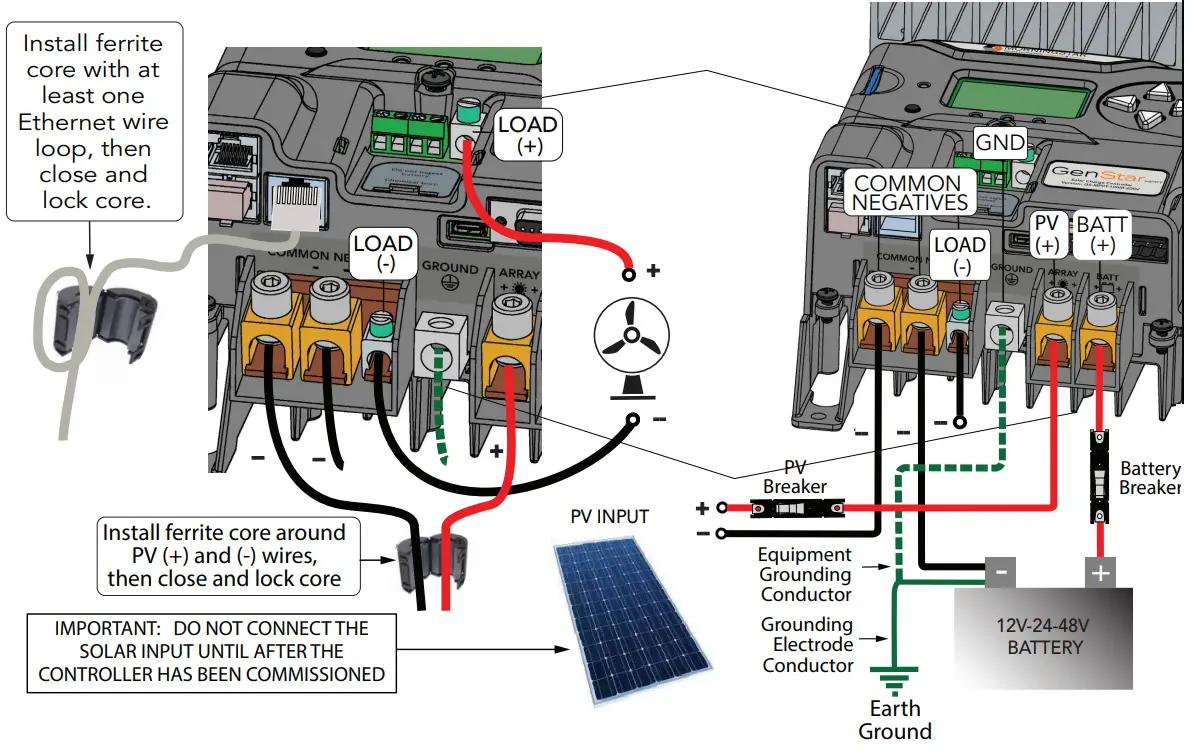
WIRING SCHEMATIC –
see accessory wiring details on p. 5 -reverse
LEGEND![]() POSITIVE CONDUCTOR
POSITIVE CONDUCTOR![]() NEGATIVE CONDUCTOR
NEGATIVE CONDUCTOR
NOTE: Actual wire routing and connection hardware components may vary.
![]() CAUTION: When installing the Gen Star MPPT, refer to product manual Section 3.1 – General Installation Notes – and all mandatory Section 3.3 Overcurrent Protection Devices and 3.4 Wiring ratings, specifications, warnings and cautions.
CAUTION: When installing the Gen Star MPPT, refer to product manual Section 3.1 – General Installation Notes – and all mandatory Section 3.3 Overcurrent Protection Devices and 3.4 Wiring ratings, specifications, warnings and cautions.
WIRED ACCESSORY INSTALLATION:
Refer to product manual Section 3.4 – Steps 1 and 2 – for important safety warnings, and additional information.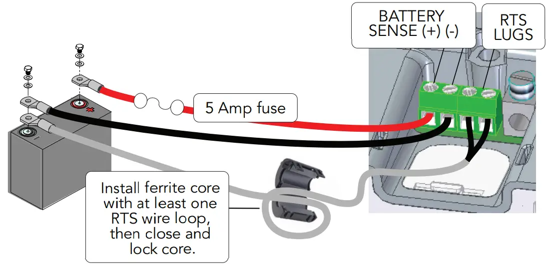 COMMISSIONING:
Commissioning requires the user to enter and confirm important settings required for basic operation. Connect the battery to initiate the commissioning procedure, and then follow the meter prompts. Do not connect the solar input until after the controller has been commissioned.
The commissioning flowchart – p. 6 – illustrates the selectable options required to prepare the Gen Star-MPPT for operation or further programming. After commissioning, 1 disconnect and then reconnect the battery to re-start the unit, 2 connect the solar input. When powering down, 3 disconnect the solar input, 4 disconnect the battery.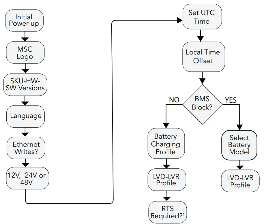 1“RTS Required”, is the default setting. Once a unit is commissioned with this default, a subsequent change to, “RTS not required”, necessitates that the unit be re- commissioned via a Factory Reset using the local meter – Installer Setup\Commands\Factory Reset. Also see RTS Start-up and Run-time Behavior Tables in the Commissioning Section of the full manual.
CONFIGURATION:
All settings – excluding factory reset – can be configured using Morningstar Live View web pages – see the main Live View web page for locations and screens. The product manual configuration sections describe all settings details in terms of Live View screens, and many settings are also accessible within the Setup-Installer Setup on-board meter menus shown below and in Section 4 of product manual.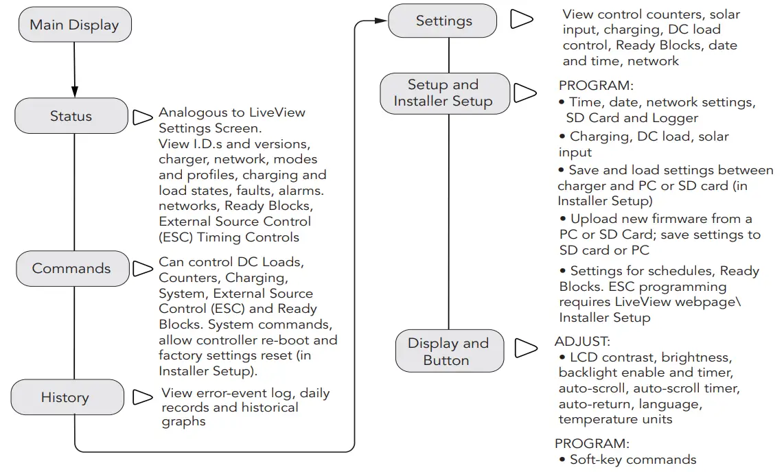
BATTERY CHARGING PRESETS and LVD-LVR PROFILES
| Battery Type-Preset | Absorption Voltage | Float Voltage | Equalization Voltage | Absorption Time | Equalization Time | Equalization Timeout |
| Volts | Volts | Volts | Minutes | Minutes | Minutes | |
| 1 – Sealed | 14.10 | 13.70 | Disabled | 150 | Disabled | Disabled |
| 2 – Sealed | 14.30 | 13.70 | 14.61 | 150 | 60 | 120 |
| 3 – Sealed / Flooded | 14.50 | 13.60 | 15.01 | 180 | 60 | 120 |
| 4 – Sealed / Flooded | 14.60 | 13.50 | 15.21 | 180 | 120 | 180 |
| 5 – Sealed / Flooded | 14.80 | 13.50 | 15.41 | 180 | 120 | 180 |
| 6 – LiFePO4 – Low2 | 13.60 | 13.50 | Disabled | 180 | Disabled | Disabled |
| 7 – LiFePO4 – Medium2 | 13.90 | 13.50 | Disabled | 20 | Disabled | Disabled |
| 8 – LiFePO4 High2 | 14.20 | 13.50 | Disabled | 15 | Disabled | Disabled |
CHARGING PRESET NOTES:
1 For Presets 2-5, an equalization charging stage can be initiated manually using the Start Equalization Command from the local meter or Live View. Auto equalization can only be set up using custom settings.
2 CAUTION: LiFePO4 settings are for 4, 8 and 16-cell LiFePO4 batteries only.
- Preset temperature compensation co-efficient for sealed or flooded batteries =
-30 Millivolts / °C / 12V — temp. comp. is disabled for LiFePO4 presets. - All settings, including charging stage voltages and timing, can be custom programmed using the local meter or Live View. Live View includes additional advanced custom programming options.
- CAUTION: Equipment Damage
Do not equalize sealed batteries with preset or custom settings unless recommended by the battery manufacturer. To prevent the possibility of unintended equalization, use custom settings to disable all equalization. - CAUTION: Settings may not be compatible with all models of these battery types.
- All voltage setting values are for 12V systems. Multiply values by two (2) for 24 Volt batteries, or by four (4) for 48 Volt systems.
See full manual for complete details on charging settings operation.
©2022 Morningstar Corporation. All rights reserved.
LVD-LVR PROFILES
| Load Control Type-Preset | LVD | LVR |
| Volts | Volts | |
| 1 – Lead Acid | 11.10 | 12.60 |
| 2 – Lead Acid | 11.50 | 12.80 |
| 3 – Lead Acid | 11.70 | 12.90 |
| 4 – Lead Acid | 12.00 | 13.20 |
| 5 – LiFePO4 | 12.50 | 13.15 |
| 6 – LiFePO4 | 12.70 | 13.25 |
| 7 – LiFePO4 | 12.85 | 13.30 |
![]() MS-003634 v4
MS-003634 v4


 Solar Mppt Charge Controller User Manual")


