![]() IVGM4648/2048 MPPT Battery Charge Controller
IVGM4648/2048 MPPT Battery Charge Controller
User Guide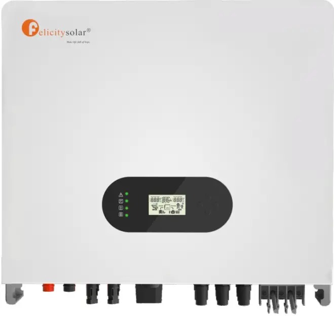
Hybrid solar inverter
About This Manual The manual mainly describes the product Information, guidelines for installation, operation and maintenance. The manual cannot include complete information about the photovoltaic (PV) system.
How to Use This Manual
Read the manual and other related documents before performing any operation on the inverter. Documents must be stored carefully and be available at all times. Contents may be periodically updated or revised due to product development. The information in this manual is subject to change without notice. The latest manual can be acquired via our website at http://www.felicitysolar.com for latest version.
Safety Introductions
This chapter contains important safety and operating instructions. Read and keep this manual for future reference.
- Before using the inverter, please read the instructions and warning signs of the battery and corresponding sections in the instruction manual.
- Do not disassemble the inverter. If you need maintenance or repair, take it to a professional service center.
- Improper reassembly may result in electric shock or fire.
- To reduce risk of electric shock, disconnect all wires before attempting any maintenance or cleaning. Turning off the unit will not reduce this risk.
- Caution: Only qualified personnel can install this device with battery.
- Never charge a frozen battery.
- For optimum operation of this inverter, please follow required specifification to select appropriate cable size. It is very important to correctly operate this inverter.
- Be very cautious when working with metal tools on or around batteries. Dropping a tool may cause a spark or short circuit in batteries or other electrical parts, even cause an explosion.
- Please strictly follow installation procedure when you want to disconnect AC or DC terminals. Please refer to ‘Installation” section of this manual for the details.
- Grounding instructions – this inverter should be connected to a permanent grounded wiring system. Be sure to comply with local requirements and regulation to install this inverter.
- Never cause AC output and DC input short circuited. Do not connect to the mains when DC input short circuits.
| Symbols | Name | Instruction |
| Danger | Serious physical injury or even death may occur if not follow the relative requirements | |
| Warning | Physical injury or damage to the devices may occur if not follow the relative requirements | |
| Electrostatic sensitive | Damage may occur if not follow the relative requirements | |
| Hot surface | Sides of the device may become hot. Do not touch. | |
| Earth terminal | The inverter must be reliably grounded. | |
| Caution | Ensure that DC and AC side circuit breakers have been disconnected and wait at least 5 minutes before wiring and checking. | |
| NOTE | Note | The procedures taken for ensuring proper operation. |
 | CE mark | The inverter complies with the CE directive. |
| EU WEEE mark | Product should not be disposed as household waste. |
Product Introduction
Felicity Solar IVGM4648/5048 is a multifunctional inverter, combining functions of inverter, solar charger and battery charger to offer uninterruptible power support with portable size. Its comprehensive LCD display offers user configurable and easy accessible button operation such as battery charging, AC/solar charging, and acceptable input voltage based on different applications.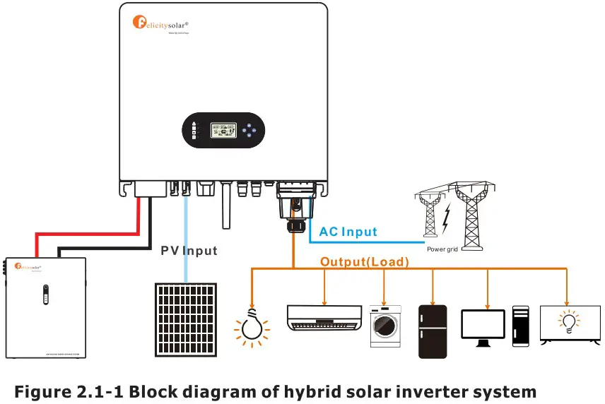 2.1 Operation Modes
IVGM system normally has the following operation modes based on your configuration and layout conditions.
Mode 1: The energy produced by the PV system is used to optimize self-consumption. The excess energy is used to recharge the batteries, the rest is exported to grid.  Mode 2: When there is no PV, and the battery is sufficient, it can supply the load together with grid power.
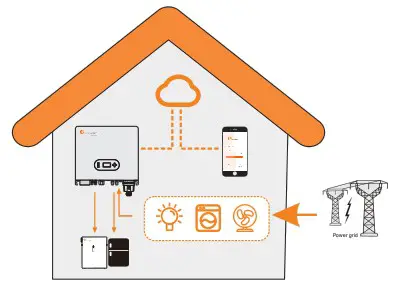
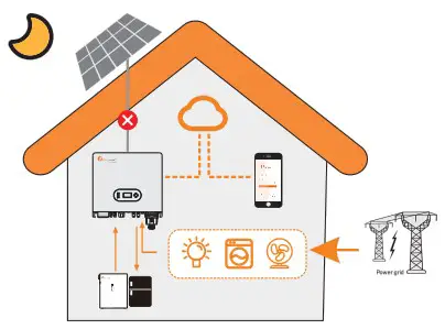 Mode 3: When grid fails, the system automatically switches to Back-Up mode. The Back-Up can be supported by pv and battery.
 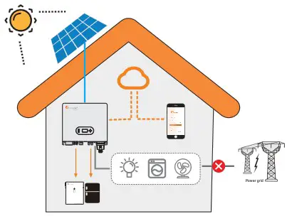 Mode 4:There is no PV, the battery is low, and the battery is charged through the grid.
2.2 Products overview 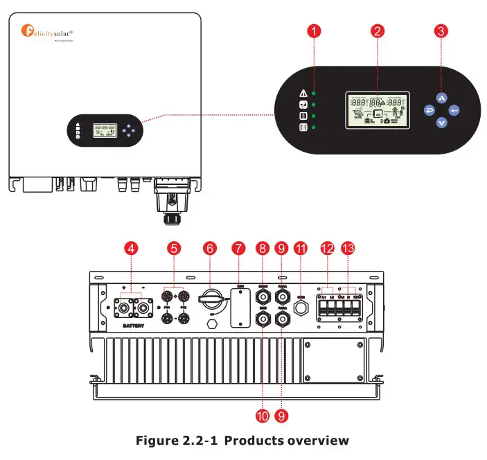
| 1. Inverter Indicators | 6. DC switch | 10. BMS port |
| 2. LCD display | 7. WIFI Communication port | 11. COM port |
| 3. Button | 8. DRMS port | 12. Back-up terminal |
| 4. Battery connection port | 9. PARA port | 13.0n-grid terminal |
| 5. PV input connection port |
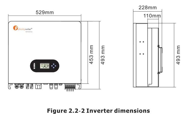
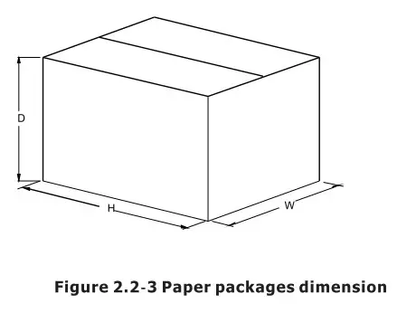 Table 2-4 Packages dimension and gross weight
| Model | H (mm) | W (mm) | D (mm) | Net Weight (KG) | Gross Weigh (KG) |
| IVGM4648/5048 | 632 | 585 | 315 | 35. | 40.0 |
Installation
3.1 Packing List
The inverter 100% strictly inspected before package and delivery. Please check the product rs or) package and fittings carefully before installation. 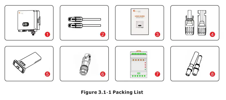
Table 3.1-1 Detailed delivery list
| No. | Name | Quantity |
| 1 | Inverter | 1 |
| 2 | Battery connector | 1 pair |
| 3 | Operation manual | 1 |
| 4 | DC connector | 2 pairs |
| 5 | WiFi module | 1 |
| 6 | COM connector | 1 |
| 7 | Meter+CT(optional) | 1 |
| 8 | Expansion Bolts | 5 |
3.2 Installation tools 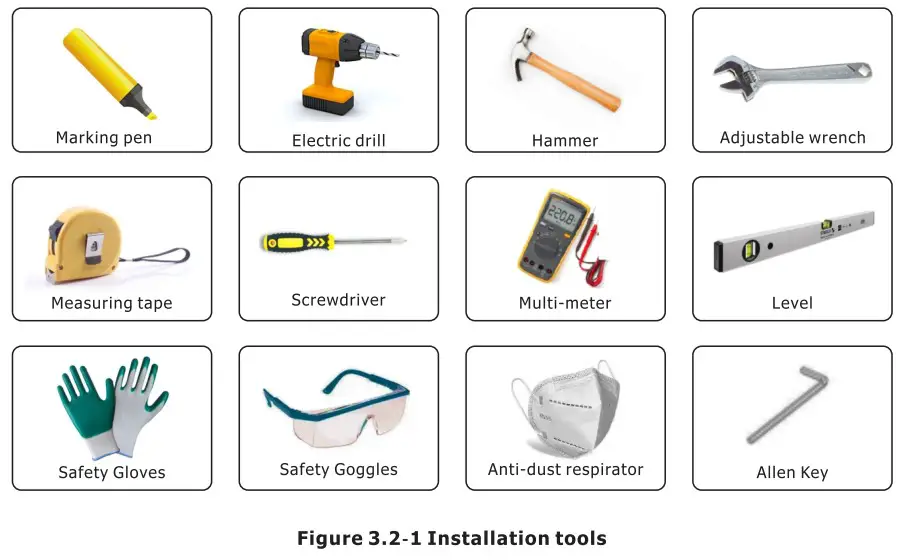 3.3 Installation Environment
- Choose a dry, clean, and tidy place, convenient for installation
- Ambient temperature range: -25°C ~ 60°C
- Relative humidity: 0 ~ 100% (non-condensed)
- Install in a well-ventilated place
- No flammable or explosive materials close to inverter
- The AC overvoltage category of inverter is category III
- Maximum altitude: 2000m
![]() Inverter cannot be installed near flammable, explosive or strong electromagnetic equipment.
Inverter cannot be installed near flammable, explosive or strong electromagnetic equipment. 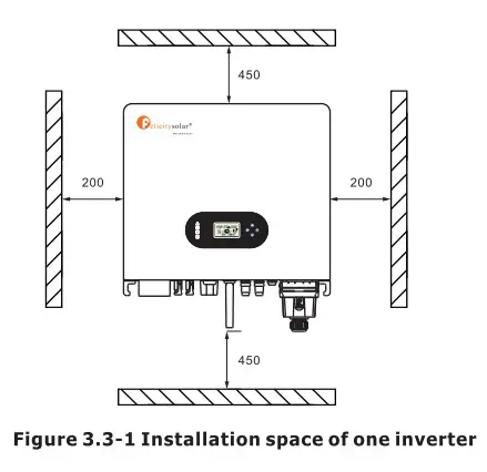 Ensure there is sufficient space for heat-releasing. Generally, space requirement should be met as below:
Table 3-3-1 Detailed installation space
| Minimum clearance | |
| Lateral | 200mm |
| Top | 450mm |
| Bottom | 450mm |
![]() *Do not open the cover of the inverter or replace any part as incomplete inverter may cause electric shock and damage the device during operation.
*Do not open the cover of the inverter or replace any part as incomplete inverter may cause electric shock and damage the device during operation.
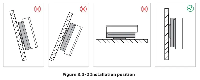
The installation of inverter should be protected under shelter from direct sunlight or badweather like snow,rain, lightning etc. 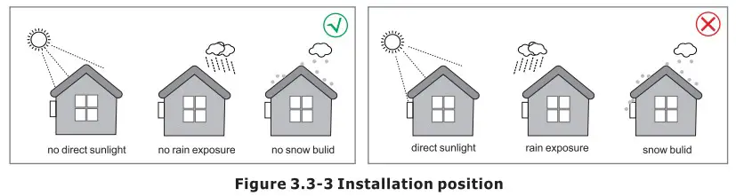 3.4 Mounting
![]() The inverter is heavy, please be careful when removing it from the package.
The inverter is heavy, please be careful when removing it from the package.
The inverter is suitable for mounting on concrete or other non-combustible surface only. Step 1. Please use the mounting bracket as a template to drill 5 holes in the right positions (10mm in diameter, and 80mm in depth). Use M8 expansion bolts in accessory box and fix the mounting With a 12mm drill bracket onto the wall tightly. The installation of inverter support is shown in Figure 3.4-1.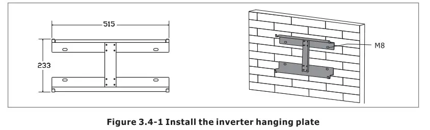 Step 2. Lift the inverter to fix it on the installation bracket, We can prevent theft by locking. See Figure 3.4-2.
NOTE *Be careful when mounting because the inverter is very heavy. 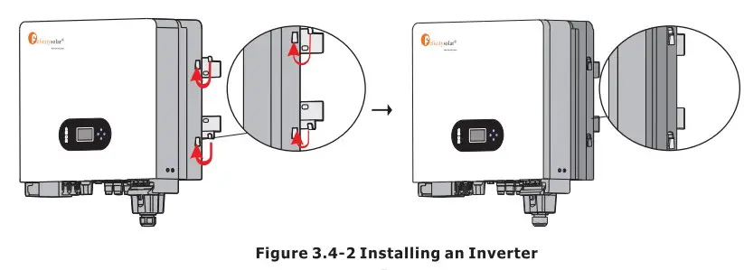
Electrical Connection
- High voltages in power conversion circuits. Lethal hazard of electric shock or serious burns.
- All work on the PV modules, inverters, and battery systems must be carried out by qualified personnel only.
- Wear rubber gloves and protective clothing (protective glasses and boots) when working on high voltage/high current systems such as INVERTER and battery systems.
4.1 PV Connection
Before connecting PV panels/strings , please make sure requirements are followed as below:
- The total short-circuit current of PV string must not exceed inverter’s max DC current.
- The minimum isolation resistance to ground of the PV string must exceed 19.33kQ in case of any shock hazard.
- PV string could not connect to earth/grounding conductor.
- Use the right PV plugs in the accessory box.
| Wire Size | Cable(mm) |
| 12AWG | 7 |
Step 1. Prepare PV positive and negative power cables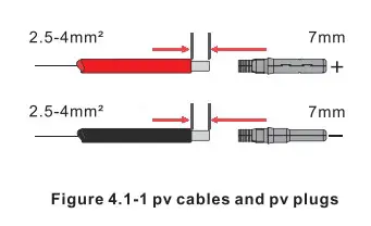 Step 2. Connect PV cables to PV connectors. See Figure 4.1-2.
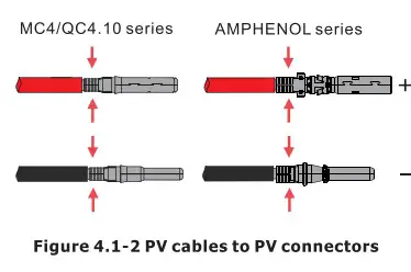
NOTE
- PV cables must be tightly crimped into the connectors.
- For Amphenol connector, the limit buckle cannot be pressed.
- There will be a “click “sound if connectors are inserted correctly into PV plugs.
Step 3. Screw the cap on and plug it onto inverter side. There will be a click sound if connectors are inserted correctly into PV plugs.See Figure 4.1-3. 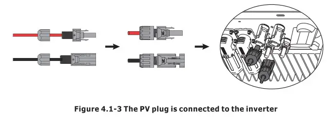
![]() The polarity of PV strings cannot be connected reversely, otherwise the inverter could be damaged.
The polarity of PV strings cannot be connected reversely, otherwise the inverter could be damaged.
4.2 Battery Connection
Please be careful about any electric shock or chemical hazard. Make sure there is an external DC breaker (125A) connected to the battery without build-in DC breaker.![]() The polarity of battery cannot be connected reversely, otherwise the inverter could be damaged.
The polarity of battery cannot be connected reversely, otherwise the inverter could be damaged.
| Wire Size | Cable(mm) |
| 1/0AWG | 25 |
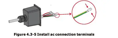
Step 1. Prepare battery cables and accessories, and route the battery power cable through the battery cover. Use accessories box accessories, battery power cable 20-35mmz2. 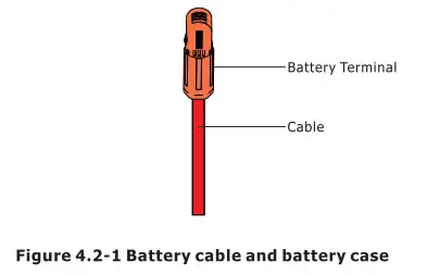 Step 2. Make battery terminals , Strip cable coat, revealing 10mm length of metal core.Use special crimper to compress battery terminal tightly.
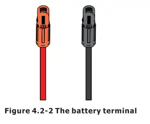 Step 3. Connect the battery terminal to the inverter. Ensure that the battery polarity is connected correctly.
 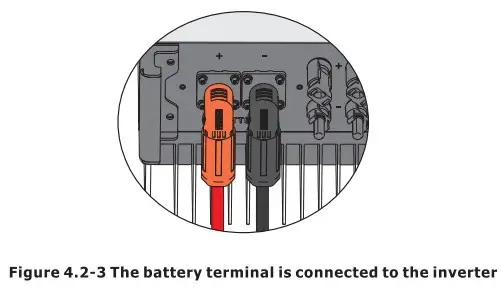 4.3 On-Grid & Back-Up Connection
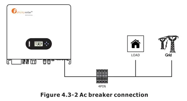
An external AC breaker is needed for on-grid connection to isolate from grid when necessary. The requirements of on-grid AC breaker are shown as below. 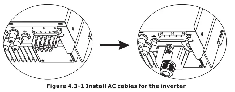
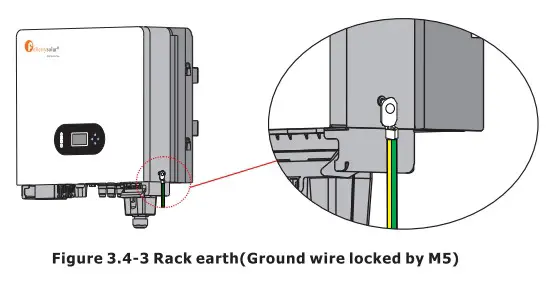
![]() Don’t connect the PE wire wrong.
Don’t connect the PE wire wrong.
Table 4.3-1 : Recommended table of AC circuit breakers
| INVERTER MODEL | AC BREAKER SPECIFIFICATION |
| IVGM4648/5048 | 40A/230V,2P |
Note
The absence of AC breaker on back-up side will lead to inverter damage if an Se electrical short circuit happens on back-up side.
- 0n the AC side, the individual breaker should be connected between inverter and Grid but before loads. See Figure 4.3-2.
 Make sure the inverter is totally isolated from any DC or AC power before connecting AC cable.
Step 1. Prepare the terminals and AC cables as below. See Figure 4.3-3. 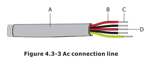 Table 4.3-2 : Ac cable specifications
| Grade | Description | Value |
| A | Outside diameter | 13-18 mm |
| 8 | Separated wire length | 20-25 mm |
| C | Conductor wire length | 7-9 mm |
| D | Conductor core section | 4-6 mm |
Step 2. Using the terminals in the accessory box, pass the AC cable through the terminal cover. See Figure 4.3-4.
Note
The absence of AC breaker on back-up side will lead to inverter damage if an Be electrical short circuit happens on back-up side.
Step 4. Connect the combined AC cable to the AC terminal of the inverter, tighten the cable to a torque of 2.0 N.m to 2.5 N.m, and then lock the AC cover.See Figure 4.3-6. 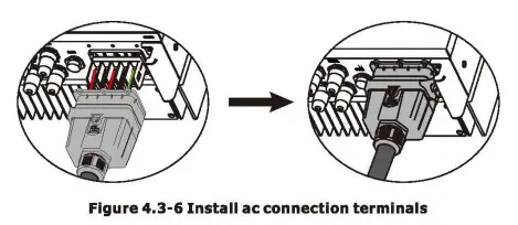 4.4 Smart Meter & CT Connection
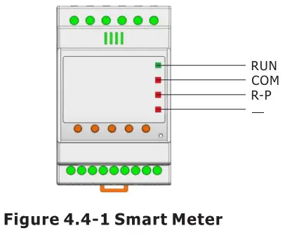
Table 4.4-1 :Smart Meter LED Indications
| STATUS | OFF | ON | Blinking |
| Run (Green) | The instrument is not running | / | The instrument is running normally |
| Com (Red) | The instrument is not communicating | / | The instrument is in communication status |
| R-P (Red) | Positive power | Negative power | / |
| — (Red) | / | Negative value indicator lamp | / |
Connection Mode
The connection diagram on the instrument housing shall prevail in case ofany discrepancies with it. 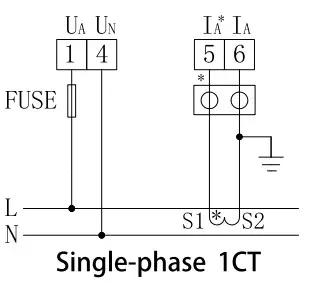 Itis recommended to use 0.5A or 3A for the fuse in the connection diagram;
![]() Make sure the inverter is totally isolated from any DC or AC power before connecting AC cable.
Make sure the inverter is totally isolated from any DC or AC power before connecting AC cable. 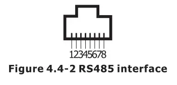 Table 4.4-2 :RS485 interface
| NO. | 1 | 2 | 3 | 4 | 5 | 6 | 7 | 8 |
| Function | 485A | 485B | 485A | GND1 | GND1 | 4856 | NC | NC |
The Smart Meter with CT in product box is compulsory for IVGM system installation, used to detect grid voltage and current direction and magnitude, further to instruct the operation condition of IVGM inverter via RS485 communication. See Table 4.4-3.
Table 4.4-3 :Detailed Pin Function Of COM Port On IVGM
| Position | Function | Note | |
| 1 | 485_A2 | RS485-2 For Meter | |
| 2 | 485_B2 | ||
| 3 | 485_A3 | RS485-3 For Remote Monitor | |
| 4 | 485_B3 | ||
| 5 | 485_A3 | ||
| 6 | 485_B3 | ||
| 7 | RY_4 | Dry Signal | |
| 8 | RY_5 |

Make sure Meter & CT are connected between house loads and grid, and follow the Smart Meter direction sign on CT, refer to Figure 4.4-3.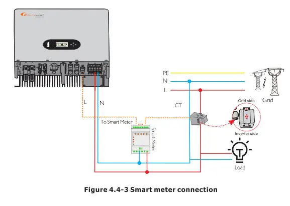
4.5 Dry Contact Signal
There is one dry contact (34/250VAC) available on the inverter.
| Unit Status | Condition | Dry contact port |
| Power Off | Unit is off and no output is powered. | Open |
| Power On | Battery voltage < Setting value in Program 12 | Close |
| Battery voltage > Setting value in Program 13 or battery charging reaches floating stage | Open |
4.6 DRMS Connection
DRMS(Demand response enabling device) is used for Australia and New Zealand installation (also used as remote shutdown function in European countries), in compliance with Australia and New Zealand safety requirements( or European countries). Inverter integrates control logic and provides an interface for DRMS. The DRMS is not provided by inverter manufacturer. Detailed connection of DRMS & Remote Shutdown are shown below:
Step 1. Screw this plate off from the inverter. See Figure 4.6-1.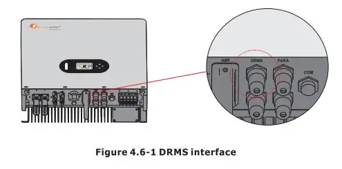 Step 2. Plug out the RJ45 terminal and dismantle the resistor on it. Plug the resistor out, leave the RJ45 terminal for next step.
 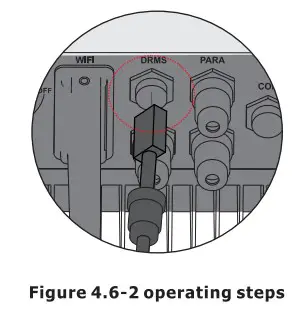 NOTE
NOTE
- The R345 terminal in the inverter has the same function as DRED. Please leave it in the inverter if no external device is connected.
Step 3-1 Pass the RJ45 cable through the steel plate and connect the DRED cable to the RJ45 terminal. As shown in Figure 4.6-3, Table 4-9 describes the 6-pin port definition. 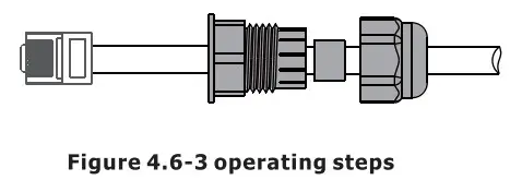 Table 4.6-1 :Port pin allocation table
| NO. | 1 | 2 | 3 | 4 | 5 | 6 |
| Function | DRM1/5 | DRM2/6 | DRM3/7 | DRM4/8 | REFGEN | COM/DRMO |
Step 3-2 For Remote Shutdown. Run the cable through the steel plate , Then wire from pins 5 and 6. Table 4.6-1 describes the 6-pin port definition, Wiring is shown in Figure 4.6-4.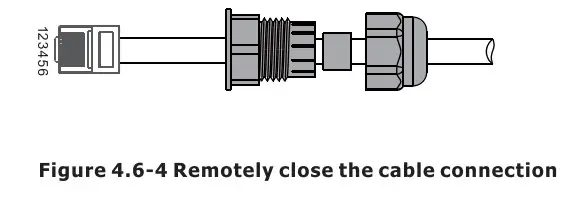 Step 4. Connect RJ45 terminal to the right position onto the inverter. See Figure 4.6-5.
 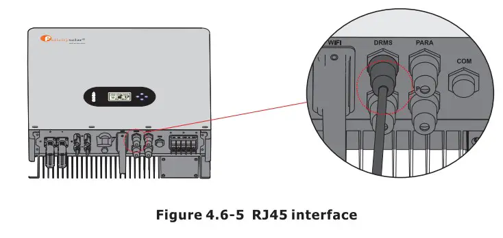 4.7 Lithium Battery Communication
It’s allowed to connect lithium battery and build communication only which it has been configured. Please follow bellow steps to configure communication between lithium battery and inverter.
- Connect power cables between lithium battery and inverter. Please pay attention to the terminals of positive and negative. Make sure the positive terminal of battery is connected to the positive terminal of inverter, and the negative terminal of battery is connected to the negative terminal of inverter.
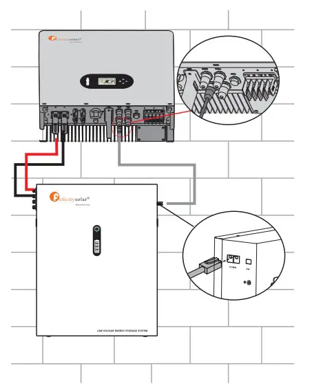
- The communication cable is bundled with lithium battery. Both sides are RJ45 port. One port is connected to the BMS port of inverter and another one is connected to the COMM port of lithium battery.

Position Color Function 1 Orange&white / 2 Orange / 3 Green&white +VCC 4 Blue COM-GND 5 Blue&white RS485-B1 6 Green RS485-A1 7 Brown & white CANL1 8 Brown CANH1 - Configure battery type to lithium battery on the app
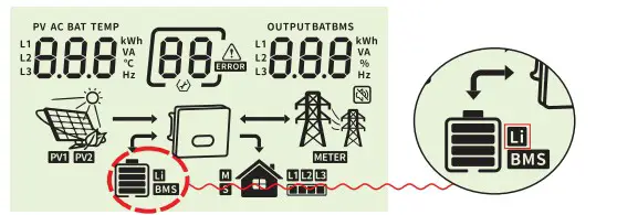
Rated Output frequency 50Hz Battery Type Lithium batt… And then LCD will show you “Li” icon.

- Power up lithium battery and inverter. Wait a moment, if the communication is built between them, LCD will show you “BMS” iconas below.

- Roll LCD real time information pages by pressing “UP” or “DOWN” button, as below page, you can see the parameters of SOC ,battery pack units and other informations in the communication system. LCD will be rolled these parameters or informations automatically.

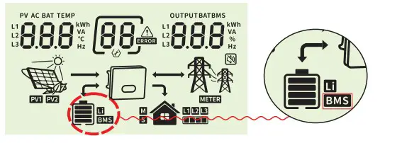

When it displays :
“p50” means BMS doesn’t allow inverter to charge battery
“p51” means BMS doesn’t allow inverter to discharge battery
“p52” means BMS require inverter to charge battery
4.8 Installation of WIFI module
The WiFi communication function applies only to the WiFi module. For details, see Figure 4.8-1 installing a WiFi module.  4.9 Wiring System
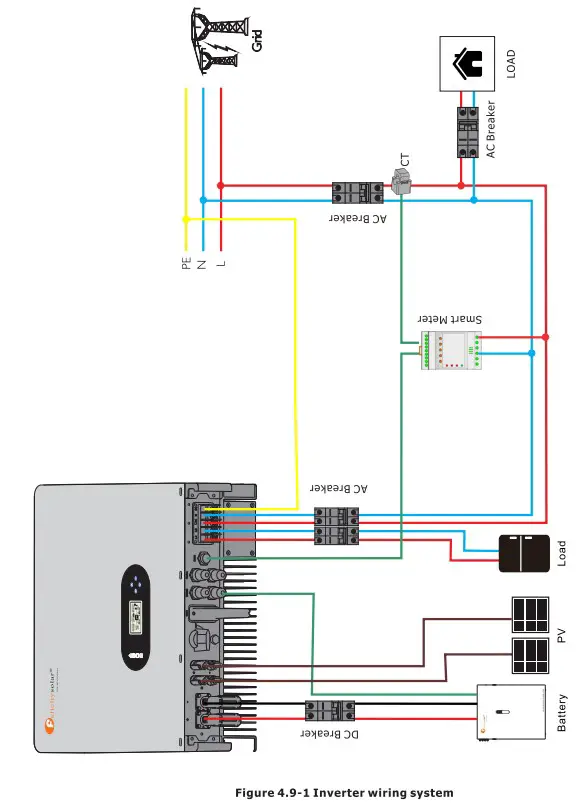
Display and operation
This chapter describes the panel displaying and how to operate which involves the LCD display, LED indicators and operation panel.
5.1 Operation and Display Panel ![]()
| Function Key | Icon | Description |
| ESC | Hold on the “ESC” button last for 3S to turn off the inveter | |
| UP | To go to previous selection | |
| DOWN | To go to next selection | |
| ENTER | Hold on the “ENTER” button last for 3S to turn on the inveter | |
| LED Indicator | Icon | Description |
| Battery | Charging the battery, the LED light flash. If battery is full, the LED light will always-on. The battery is not charged, the LED light will go out. | |
| Utility | Inverter running in utility mode, the LED will always-on. Inverter is not running in utility mode, the LED will go out. | |
| Inverter | Inverter running in off-grid mode, the LED light will always-on. Inverter is not running in off-grid mode, the LED light will go out. | |
| Fault | If inverter in fault event, the LED light will always-on. If inverter in warning event, the LED light will flash. Inverter work normally, the LED light will go out. | |
| Buzzer Information | ||
| Buzzer beep | Turn on/off the inverter, the buzzer will last for 2.5s. Press any button, the buzzer will last for 0.1s. Hold on the “ENTER” button, the buzzer will last for 3s. If in fault event, the buzzer will keep going. If in warning event, the buzzer will beep discontinuous (Check more information on the chapter of “Warning Code Table”). | |
5.2 LCD Display Icons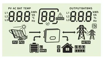
| Icon | Function description |
| Input Source Information | |
| Indicate input voltage, input frequency, PV voltage, PV power, battery voltage and charger current. | |
| Configuration Program and Fault Information | |
| Indicates the want’ and fault codes. Waning Fault: | |
| Output Information | |
| Indicate output voltage, output frequency, load percent, load In VA, load In Watt and discharging current. | |
| Battery Information | |
| Indicates battery level by 0-24%, 25-49%, 50-74% and 75-100%. | |
| Indicates Lithium battery type. | |
| Indicates communication is built between inverter and battery. | |
Mode Operation Information
| Indicates the utility. | |
| Indicates load level by 1-25%, 26-50%, 51-75% and 76-100% | |
| Indicates the PV panels. |
| Indicates PV MPPT is working. | |
| Indicates communication is built between inverter and meter | |
| Mute Operation | |
| Indicates unit alarm is disabled. | |
5.3 Base information Page
The base information will be switched by pressing “UP” or “DOWN” key. The selectable information is switched as below order:
Input voltage / Output voltage
Utility voltage is 230V, output voltage is 230V 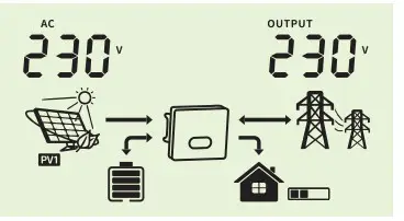 Input frequency / Output voltage
Utility frequency is 50.0Hz, output voltage is 230V 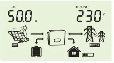 PV1 voltage / Output voltage
PV1 voltage is 450V, output voltage is 230V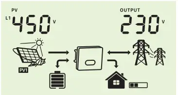 PVi power / Output voltage
PV1 power is 3.00kW, output voltage is 230V 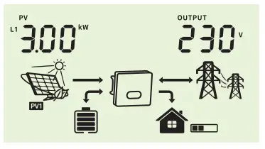 PV2 voltage / Output voltage
PV2 voltage is 450V, output voltage is 230V  Pv2 power / Output voltage
Pv2 power is 3.00kW, output voltage is 230V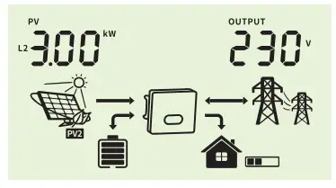 Battery voltage / Output voltage
Battery voltage is 50.0V, output voltage is 230V 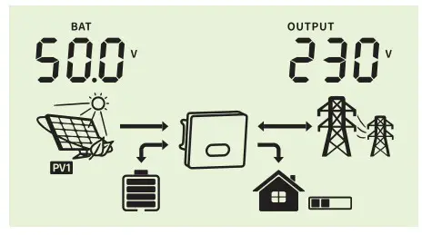 Charging current / Output voltage
Charging current is 10A, output voltage is 230V 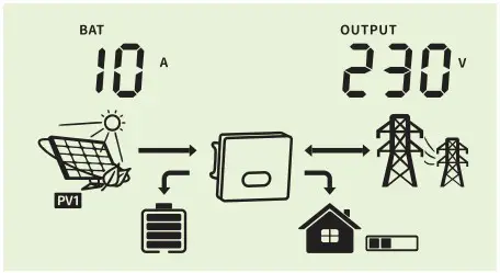 Battery voltage / Output frequency
Battery voltage is 50.0V, output frequency is 50.0Hz 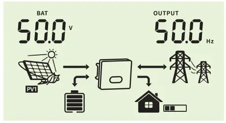 Battery voltage / Load percentage
Battery voltage is 50.0V, load percentage is 40%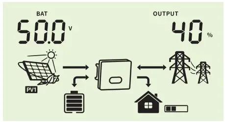 Battery voltage / Load VA
Battery voltage is 50.0V, output wattage is 2.00kVA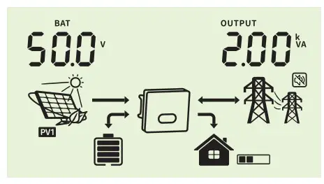 Battery voltage / Load wattage
Battery voltage is 50.0V, output wattage is 2.00kWBattery voltage / Discharging current
Battery voltage is 54.0V, discharging current is 40A 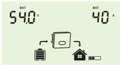 CPU software version
CPU software version is 1100 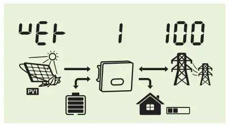
Warning Code Table
When fault event happens, the fault LED is flashing. At the same time, warning code, icon ![]() is shown on the LCD screen.
is shown on the LCD screen.
| Warning Code | Warning Information | Audible Alarm | Trouble Shooting |
| 7 | Low battery | The battery voltage is too low, it should be charging. | |
| 9 | Overload | Beep twice every second | Reduce the loads. |
| 51 | BMS doesn’t allow inverter to discharge battery. | Inverter will stop discharging battery automatically. | |
| 52 | BMS require inverter to charge battery. | Inverter will charge battery automatically. | |
| 60 | BMS firmware version is not matched. | Upgrade the firmware of BMS. |
Troubleshooting
This chapter describes the fault alarm and fault code for quick troubleshooting.
Table 7-1 Fault code
| Fault Code | Fault information | Trouble Shooting |
| 1 | PV voltage is too high | Reduce the number of Pv modules in series. |
| 2 | Over current happen at PV port | Restart the unit, if the error happens again, please return to repair center. |
| 4 | Stort circuit happen at PV port | Check if wiring is connect well. |
| 7 | Battery voltage is too high | Check if spec and quantity of batteries are meet requirements. |
| 8 | Over current happen at Battery | Restart the unit, if the error happens again, please return to repair center. |
| 10 | Abnormal LLC | Restart the unit, if the error happens again, please return to repair center. |
| 11 | Over current happen at Buck boost | Restart the unit, if the error happens again, please return to repair center. |
| 13 | Buck boost soft start failed | Restart the unit, if the error happens again, please return to repair center. |
| 14 | Buck Boost is out of balance | Restart the unit, if the error happens again, please return to repair center. |
| 15 | Buck boost current sensor failed | Restart the unit, if the error happens again, please return to repair center. |
| 16 | NO.2 Backmost current sensor failed | Restart the unit, if the error happens again, please return to repair center. |
| 17 | Overload time out | Reduce the connected load by switching off some equipment. |
| 18 | The output overcurrent is abnormal | Restart the unit, if the error happens again, please return to repair center. |
| 19 | Output short circuited | Check if wiring is connected well and remove abnormal load. |
| 21 | OP current sensor failed | Output current sensor failed |
| 22 | Output voltage is too low | Reduce the connected load. |
| 23 | Output voltage is too high | Restart the unit, If the error happens again, please return to repair center. |
| 24 | Over current or surge detected by Software | Restart the unit, if the error happens again, please return to repair center. |
| 25 | Hardware detect over current at inverter port | Restart the unit, if the error happens again, please return to repair center. |
| 26 | Invert soft start failed | Internal components failed. Restart the unit, If the error happens again, please return to repair center. |
| 28 | The DCcomponentof the inverter current is abnormal | Restart the unit, if the error happens again, please return to repair center. |
| 29 | Inverter current sensor failed | Restart the unit, If the error happens again, please return to repair center. |
| 30 | Bus voltage Is too low | Restart the unit, If the error happens again, please return to repair center. |
| 31 | Bus voltage Is too high | AC Surge or internal components failed. Restart the unit, if the error happens again, please return to repair center. |
| 33 | Bus soft start failed | Internal components failed. Restart the unit, if the error happens again, please return to repair center. |
| 34 | Over temperature happen at heat sink | Check whether the ambient temperature is too high. |
| 35 | The inner temperature over | Check whether the ambient temperature is too high. |
| 38 | Leakage current fault | Restart the unit, if the error happens again, please return to repair center. |
| 39 | Leakage current sensor failed | Restart the unit, If the error happens again, please return to repair center. |
| 40 | Isolation resistancetoground tithe PV siring Is too knave | Restart the unit, if the error happens again, please return to repair center. |
| 41 | Grounding errors | 1.Confirm correct grounding. 2.Restart the unit, if the error happens again, please return to repair center. |
| 42 | Relay check failure | Restart the unit, if the error happens again, please return to repair center. |
| 43 44 | CAN data loss | 1.Check if communication cables are connected well and restart the inverter. 2.If the problem remains, please contact your installer. |
| Host data loss | ||
| 45 | Synchronization data loss | |
| 46 | The firmware version of each inverter is not the same. | 1.Update all inverter firmware to the same version. 2.Check the version of each inverter via LCD setting and make sure the CPU versions arc same. If not, please contact your installer to provide the firmware to update. 3.After updating, if the problem still remains, please contact your installer. |
| 47 | The inverter Settings are inconsistent | 1.Through the LCD control button on the inverter, the parameters of the machine are set to the same as those of other machines. 2.If the problem persists, contact the after-sales service |
| 48 | Parallel installation is abnormal | Contact after-sales service for Installation technical guidance |
| 49 | Parallel negative power protection | Restart the unit, if the error happens again, please return to repair center. |
| 50 | EEPROM failure | Restart the unit, If the error happens again, please return to repair center. |
| 51. | DSP1 communication failure | Restart the unit, if the error happens again, please return to repair center. |
| 52 | DSP2 communication failure | Restart the unit, if the error happens again, please return to repair center. |
Appendix
| Model | IVG M4648 | IVGM SO48 |
| Battery Input Data | ||
| Battery Voltage Range | 40V-60V | |
| Max. charging and discharging current | 100A/100A | |
| Max. charging and discharging power | 4600W | 5000W |
| Battery type | LI-Ion /Lead-acid | |
| DC Input Data (PV side) | ||
| Max. recommended PV power | 6000W | 6500W |
| Max. PV voltage | 550V | |
| Start voltage | 130V | |
| PV voltage range | 90V-550V | |
| MPPT voltage range | 100Vem500V | |
| MPPT Voltage Range for Full Load | 200V-500V | 200V-500V |
| Nominal voltage | 360V | |
| Max. input current | 15A/15A | |
| Max. shorted curent | 18A/18A | |
| Number of MPP trackers / strings per MPP tracker | Ul | |
| Grid Data | ||
| Nominal Input Voltage | 230Vac | |
| Input Voltage Range | 184-264.5Vac* | |
| Nominal grid frequency | 50/6011r | |
| Max. input current | 40A | |
| Max. Charge Current | 100A | |
| Max. AC output power | 4600W | 5000W |
| AC Output Rated Current | 20A | 21.7A |
| Max. output current | 25A | 25A |
| Max. Continuous AC Passthrough | 30A | |
| Power factor | >0.99 | |
| Displacement power factor | 0.81eading…0.81agging | |
| THDI | <3% | |
| AC Output Data(Back Up) | ||
| Rated output power | 5000VA/5000W | |
| Max. Output current | 30A | |
| Rated AC output voltage | 230Vac | |
| Rated AC output frequency | 50/60Hz | |
| Effciency | ||
| Max. efficiency | 98.% | |
| Euro efficiency | 97.% | |
| MPPT efficiency | 100.% | |
| protection | ||
| Output over current protection | Integrated | |
| Output over power protection | Integrated | |
| Output shorted protection | Integrated | |
| Anti-islanding protection | Integrated | |
| GFCI Protection | Integrated | |
| Insulation Resistor Detection | Integrated | |
| General Data | ||
| Operating temperature range | —25°C-60°C,>45°C Derating | |
| Protection degree | 1P65 | |
| Relative humidity | 100% | |
| Cooling concept | Nature | |
| Altitude | 2000m | |
| Communication | RS232/RS485 | |
| BMS Communication | CAN/RS485 | |
| Monitor module | WiFi/GPRS | |
| Display | LCD+LED | |
| Installation Style | Wall-mounted | |
| Warranty | 10 years | |
| Grid Regulation | G99/1; EN50549-1; MI 0-21; AS 4777.2; NRS 097-24; | |
| Safety Regulation | IEC 62109-1/2 . IEC 62040-1 | |
| EMC | EN61000-6-1 . EN61000-6-3 | |
| Net Weight | 34.8KG | |
| Gross Weight | 40.0KG | |
| Product Dimension | 528*493*229MM | |
| Package Dimension | 632*585*315MM | |
- According to local grid-connected standards
Features:
- Support WiFi for mobile monitoring
- 48V low voltage battery, transformer isolation topology
- Max. charging/discharging current of 100A
- AC couple to retrofit existing solar system
- Support storing energy from diesel generator
- Power supply can be switched automatically and switching time within 20ms


 Solar Mppt Charge Controller User Manual")


