
![]()

Scan QR Code to go directly to the ProStar MPPT Installation Manual and warranty information online.

Quick Start Guide
Safety Information:
 Warning: Shock Hazard
The ProStar MPPT controller must be installed by a qualified technician in accordance with the electrical regulations of the country of installation.
Warning: Shock Hazard
This unit is not provided with a GFDI device. This charge controller must be used with an external GFDI device as required by the Article 690 of the National Electrical Code for the installation location.
 IMPORTANT: READ the ProStar Installation Manual for safety and regulatory information, instructions on configuration and operation, and warranty information.
Warranty Registration: https://www.morningstarcorp.com/product‐registration/
In the box:
ProStar Charge Controller Mounting Template

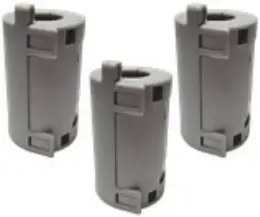
Mounting Screws (x4) Ferrite Chokes
*A Menu Map is also included with metered versions, but is not shown in this guide.
Tools Required:
![]() — #2 Philips Screwdriver
— #2 Philips Screwdriver![]() — 3/16 (5 mm) & 3/32″ (2.5 mm) Flathead Screwdriver
— 3/16 (5 mm) & 3/32″ (2.5 mm) Flathead Screwdriver
— Drill with a 1/8″ (3 mm) bit
Optional Accessories
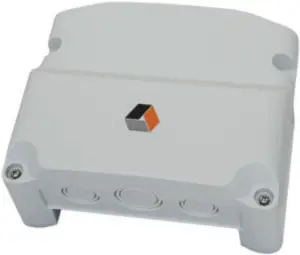
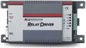
Wire Box Relay Driver (RD‐1)
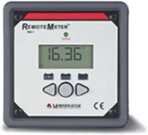
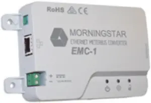
Remote Meter (RM‐10) Ethernet MeterBus Converter (EMC‐1)

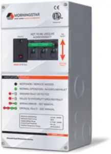
Remote Temperature Sensor (RTS) PV Ground Fault Protection (GFPD‐150V and GFPD‐600V)
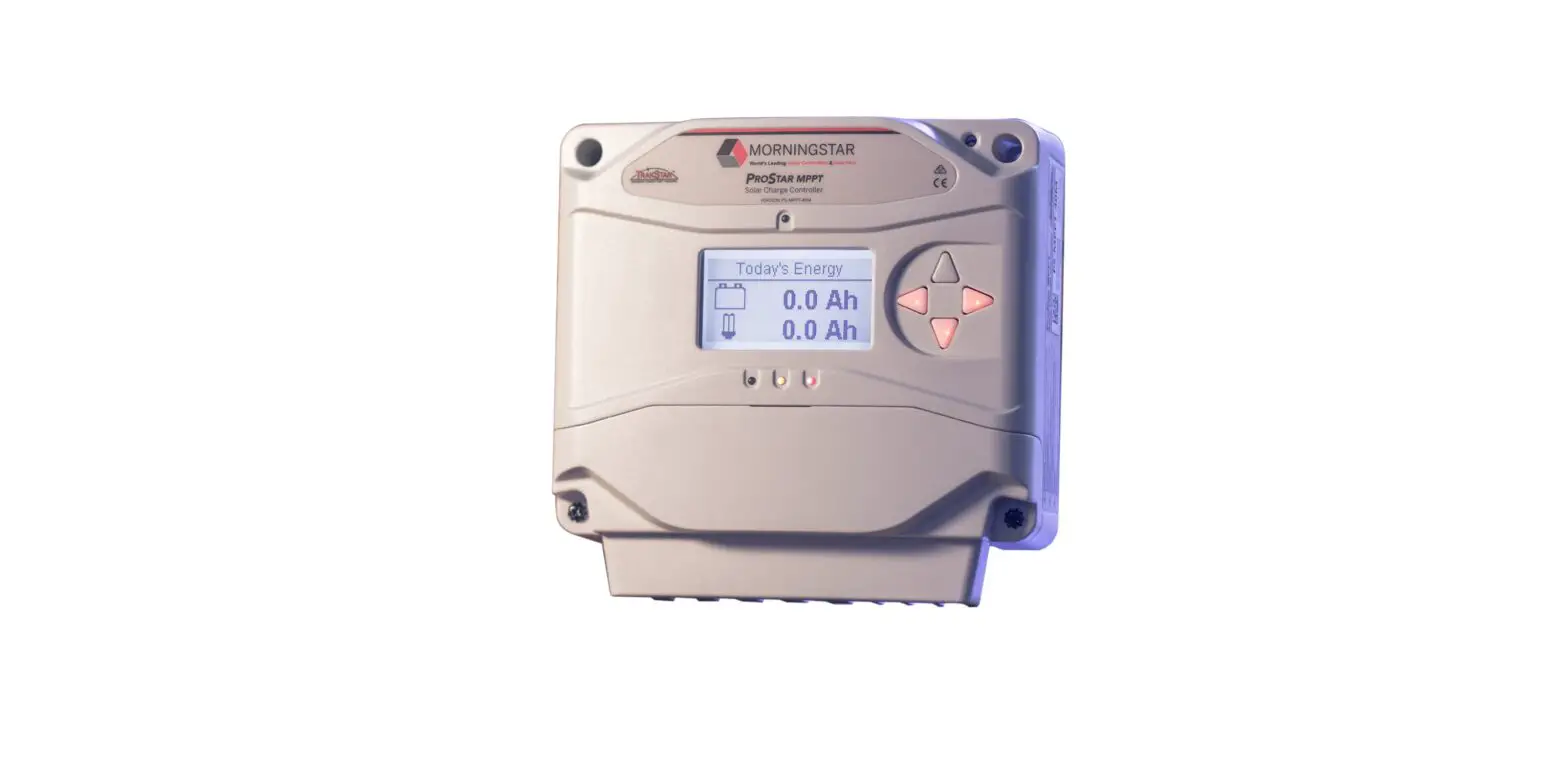
ProStar MPPT™ Charge Controller Quick Start Guide
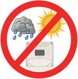
 Caution: Equipment Damage
Do not expose the ProStar CC to weather. Locate in a dry, protected area to prevent equipment damage. Ensure the minimum clearance requirements are followed to provide adequate ventilation and prevent the unit from overheating.
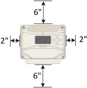
Minimum Clearance Requirements
Mounting:
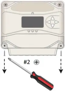
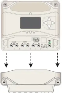
- Remove the front cover of the charge controller.
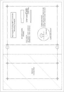
Remove the front cover from the Wire Box, if included. - Use the Mounting Template to pre‐drill the mounting holes.
a. For the ProStar Charge Controller:
Drill holes 1, 2, 3, & 4.
b. To include the optional Wire Box:
Drill the additional holes A, B, C, & D. - Place a screw on which to hang the controller in holes 1 & 2.
Back the screw out to 0.150″ or (3.8 mm).
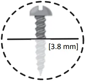
Screw Head Height for #1 & #2:
0.150″ (3.8 mm) off back plane
Do NOT exceed 0.250″ (6.4 mm)
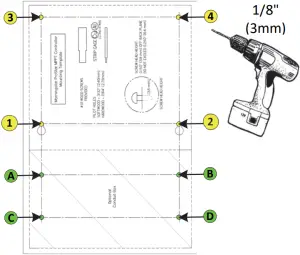
Mounting Template
4. Place the controller onto the hanging screws.
Secure the controller in place with the other 2 screws (3 & 4).
5. Place the Wire Box (if used) below the controller and secure in place using it’s mounting screws in holes A, B, C & D.
| Wiring and Torque Requirements | |||
| Component | Wire Size | Tool Required | Torque (Max) |
| Power Terminals | 2.5 ‐ 16 mm2 / #14 ‐ 6 AWG | 3/16″(5 mm) Flathead Screwdriver | 35 in‐lbs. (3.9 Nm) |
| Battery Voltage Sense | 0.25 ‐ 1.0 mm2 / #24 ‐ 16 AWG | 3/32″ (2.5 mm) Flathead Screwdriver | 5 in‐lbs. (0.56 Nm) |
| Remote Temperature Sensor | (included) | 3/32″ (2.5 mm) Flathead Screwdriver | 5 in‐lbs. (0.56 Nm) |
| Optional Wire Box | #2 AWG (Max.) | 3/16″(5 mm) Flathead Screwdriver | 35 in‐lbs. (3.9 Nm) |
| Cover Screws (ProStar or Wire Box) | — | #2 Philips Screwdriver | 5 in‐lbs. (0.56 Nm) |
Photovoltaic (PV) Array 
See the Morningstar PV String Calculator at:
http://string‐calculator.morningstarcorp.com/
IMPORTANT: Example only. Actual wiring may vary. READ the ProStar Installation, Operations, and Maintenance Manual for mandatory safety requirements. All configuration must comply with local and national electric codes. Consult your local electric authority to ensure compliance.
This illustration represents a typical off‐grid installation. For use with an inverter, refer to the inverter’s installation manual for additional information.
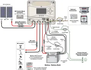
NOTE: The optional wire box is not shown in this illustration as wiring does not change.
Power UP Sequence:
1. Connect Battery/Battery Bank.
2. Connect Solar.
Power DOWN Sequence:
1. Disconnect Solar.
2. Disconnect Battery/Battery Bank.
IMPORTANT:
Ensure there is only 1 DC Negative‐to‐Ground Bond in the entire system.
Specifications:
| PS‐MPPT‐25 | PS‐MPPT‐40 | |
| Nominal Battery Voltage | 12/24 V | 12/24 V |
| Max. PV Open‐Circuit Voltage | 120 V | 120 V |
| Nominal Maximum Input Power | 350 / 700 W | 560 / 1120 W |
| Maximum Battery Charging Current | 25 A | 40 A |
| Rated Load Current | 25 A | 30 A |
Warning: Shock Hazard
Test between all terminals and ground before touching.
Power or accessory terminals are NOT electrically isolated from DC input and may be energized with hazardous solar voltage.
Operational Configuration:
Switch 1: Load/Lighting
| Mode | Switch 1 |
| Normal | OFF |
| Lighting | ON |
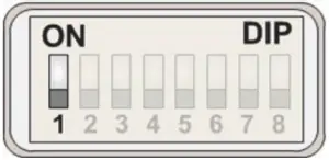
Normal Lighting
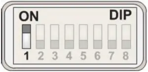
Switches 2 & 3: System Voltage
| System Voltage | Switch 2 | Switch 3 |
| Auto | OFF | OFF |
| 12 | OFF | ON |
| 24 | ON | OFF |
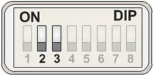
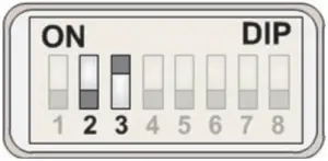
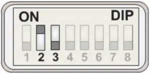
AUTO 12 V 24 V
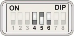
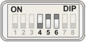
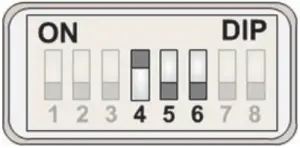
Switches 4, 5, & 6: Battery Type Selection
NOTE: The ProStar MPPT can be programmed to accommodate a wide range of charging parameters.
Consult the battery manufacturer for optimal battery charging settings.
To Change Settings:
- On metered models, use the interface on the meter or use the software available at https://www.morningstarcorp.com/msview/.
- On non‐metered models, use the software available at https://www.morningstarcorp.com/msview/.
See the ProStar Installation, Operations, and Maintenance Manual for additional information/guidance.
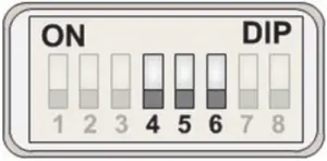
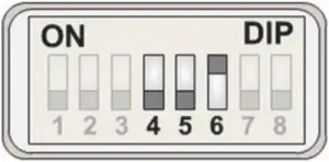
1 – Sealed* 2 – Sealed*
3 – Sealed* 4 – AGM/Flooded*
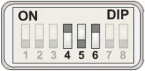
5 – Flooded 6 – Flooded
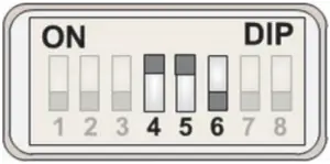
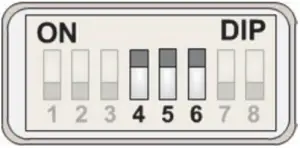
7 – L‐16 Custom**
| DIP Switch Setting | Battery Type | Absorption Stage (Volts) | Float State (Volts) | Equalize Stage (Volts) | Absorption Time (Minutes) | Equalize Time (Minutes) | Equalize Timeout (Minutes) | Equalize Interval (days) | LVD (Volts) | LVR (Volts) | ||
| 4 | 5 | 6 | ||||||||||
| OFF | OFF | OFF | 1 – Sealed* | 14.00 | 13.50 | ‐‐‐ | 150 | ‐‐‐ | ‐‐‐ | ‐‐‐ | 11.5 | 12.6 |
| OFF | OFF | ON | 2 – Sealed* | 14.15 | 13.50 | 14.40 | 150 | 60 | 120 | 28 | 11.5 | 12.6 |
| OFF | ON | OFF | 3 – Sealed* | 14.30 | 13.50 | 14.60 | 150 | 60 | 120 | 28 | 11.5 | 12.6 |
| OFF | ON | ON | 4 – AGM/Flooded* | 14.40 | 13.50 | 15.10 | 180 | 120 | 180 | 28 | 11.5 | 12.6 |
| ON | OFF | OFF | 5 – Flooded | 14.60 | 13.50 | 15.30 | 180 | 120 | 180 | 28 | 11.5 | 12.6 |
| ON | OFF | ON | 6 – Flooded | 14.70 | 13.50 | 15.40 | 180 | 180 | 240 | 28 | 11.5 | 12.6 |
| ON | ON | OFF | 7 – L‐16 | 15.40 | 13.40 | 16.00 | 180 | 180 | 240 | 14 | 11.5 | 12.6 |
| ON | ON | ON | 8 – Custom** | Custom | Custom | Custom | Custom | Custom | Custom | Custom | Custom | Custom |
| *“Sealed” battery types include Gel and AGM Batteries **Lithium‐ion and some other battery types require custom programming. Morningstar provides downloadable settings for selected battery manufacturers here: https://www.morningstarcorp.com/energy‐storage‐partner‐program/ | ||||||||||||
| Shared Settings | Set Point |
| Absorption Extension Voltage | 12.50 Volts |
| Absorption Extension Time | Absorption Time +30 minutes |
| Float Exit Time‐Out | 60 minutes |
| Float Cancel Voltage | 12.10 Volts |
| Equalize Time‐Out | Equalize Time +60 minutes |
| Temperature Compensation Co‐Efficient | –30 millivolts / °C / 12 Volts |
Switch 7: Battery Equalization
| Mode | Switch 7 |
| Manual Equalization | OFF |
| Auto‐Equalization | ON |
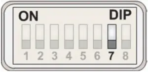
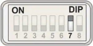
Manual EQ Auto EQ
Switch 8: Meterbus/MODBUS Settings
| Mode | Switch 8 |
| Meterbus | OFF |
| MODBUS | ON |
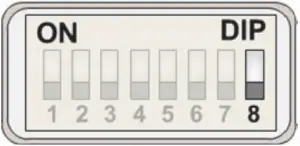
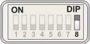
Meterbus MODBUS
Contact Information:
Technical Support: Support.morningstarcorp.com
Phone: 1‐215‐321‐4457


© 2020 Morningstar Corporation. All Rights Reserved.
MS‐001538 rev.B


 Solar Mppt Charge Controller User Manual")


