MORNINGSTAR SS-6 SunSaver Solar Controller
Quick Start Guide
| SunSaver Models: | ||
| SS‐6 | SS‐10 | SS‐20L* |
| SS‐6L* | SS‐10L* | |
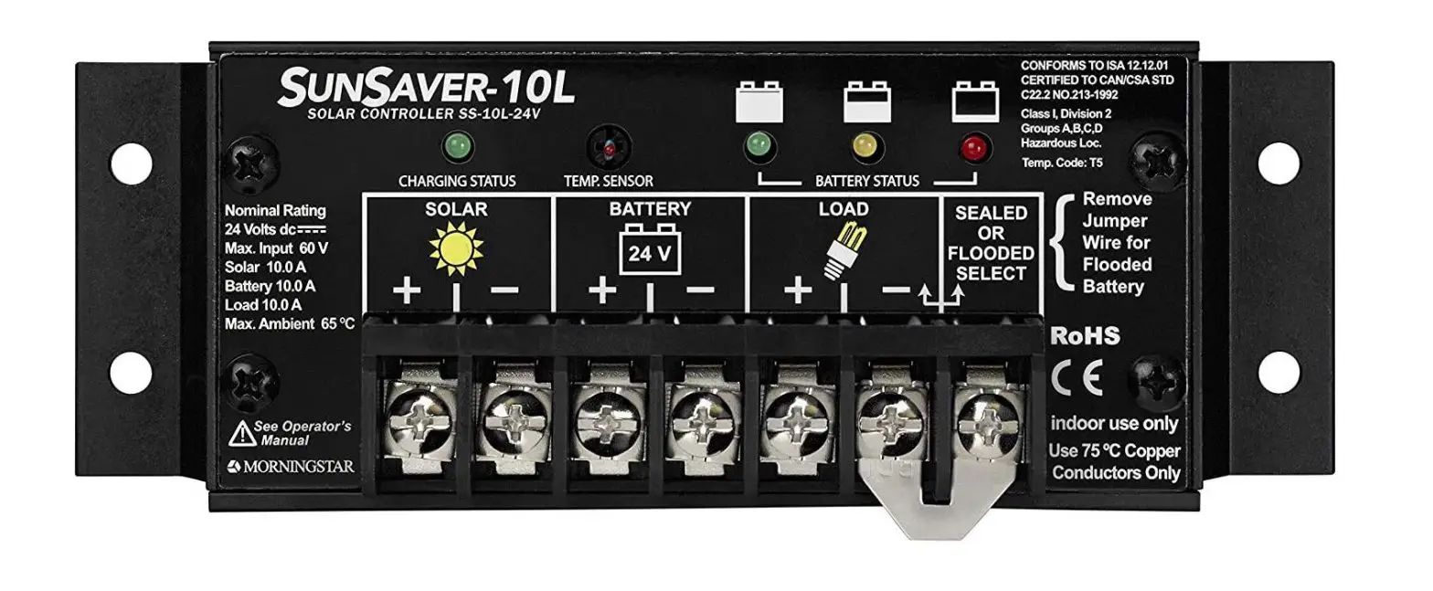
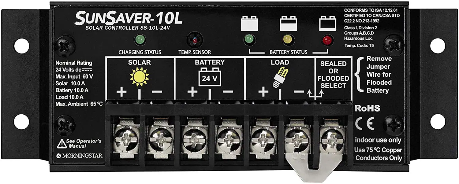
Automatic Load Control:
Load Control automatically disconnects and reconnects system loads based upon the Low Voltage Disconnect (LVD) and Low Voltage Reconnect (LVR) voltage thresholds.
The LVD and LVR thresholds are listed on Page 4 of this Quick Start Guide.
This feature is exclusive to models SS‐6L, SS‐10L, and SS‐20L only.
Scan QR Code to go directly to the SunSaver Installation Manual and warranty information online.
In the Box
Tools Required:
- #2 Philips Screwdriver
- 3/16 (5 mm) & 3/32″ (2.5 mm) Flathead Screwdriver— Drill with a 3/32″ (2.5 mm) bit
- Multimeter


Mounting
Step 1: Choose Mounting Location
Locate the SunSaver on a vertical surface within 10 feet (3 m) of the battery bank that is protected from direct sun, high temperatures, and water.
Step 2: Check for Clearance and Ventilation
- Place the SunSaver in the location where it will be mounted.
- Verify that there is sufficient room to run wires and that
- there is ample room above and below the controller for airflow.
Step 3: Mark Holes
- Use a pencil or pen to mark the four (4) mounting hole locations on the mounting surface.
Step 4: Drill Holes
- Remove the controller and drill 3/32” (2.5 mm) holes in the marked locations.
Step 5: Secure Controller
- Place the controller on the surface and align the mounting holes with the drilled holes in step 4. Secure the controller in place using the mounting screws (included).

Important Safety Information
WARNING: Shock Hazard
The SunSaver solar controller must be installed by a qualified technician in accordance with the electrical regulations of the country of installation.
This unit is not provided with a GFDI device. This charge controller must be used with an external GFDI device as required by Article 690 of the National Electrical Code for the installation location.
READ the SunSaver Installation Manual for safety and regulatory information, instructions on configuration and operation, and warranty information.
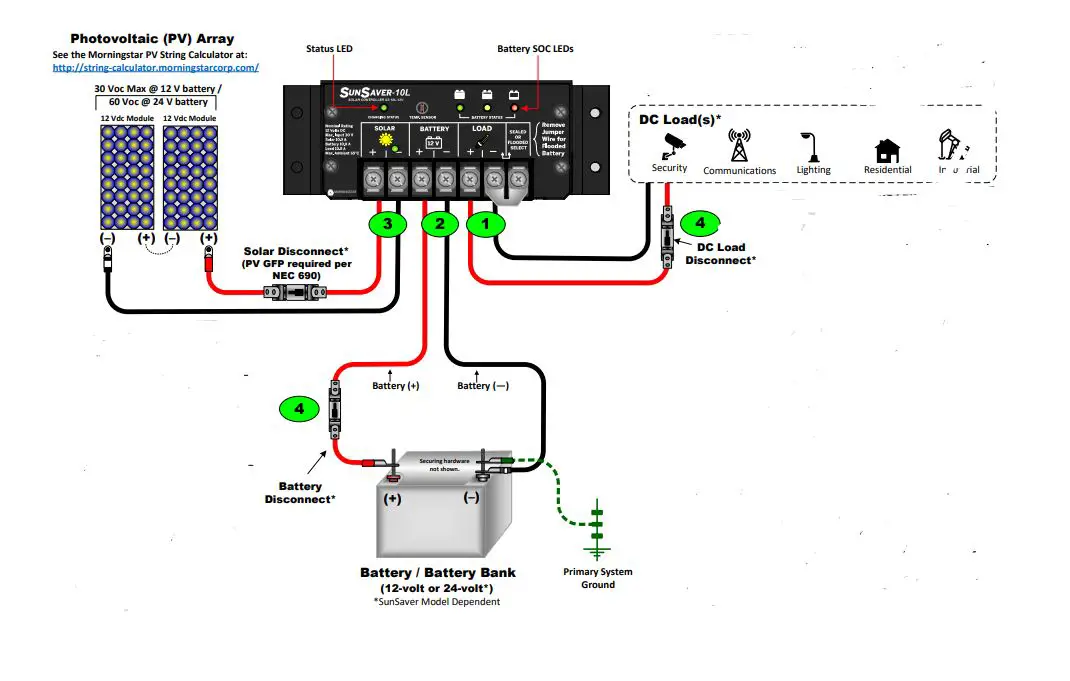
Example only. Actual wiring may vary. READ the SunSaver Installation, Operations, and Maintenance Manual for mandatory safety requirements. All configurations must comply with local and national electric codes. Consult your local electric authority to ensure compliance.
| STATUS LED | ||
| Color | Indication | Operating State |
| None | OFF (with heartbeat1) | Night |
| Green | ON Solid (with heartbeat2) | Charging |
| Red | Flashing | Error |
| Red | ON Solid (with heartbeat2) | Critical Error |
| BATTERY STATE-OF-CHARGE (SOC) LED | |||
| SOC LED | Indication | Battery Status | Load Status |
| Green | Fast Flashing (2 Flash / sec) | Equalize Charge | Load ON |
| Green | Medium Flashing (1 Flash / sec) | Absorption Charge | Load ON |
| Green | Slow Flashing (1 Flash / 2 sec) | Float Charge | Load ON |
| Green | ON Solid | Nearly Full | Load ON |
| Yellow | ON Solid | Half Full | Load ON |
| Red | Flashing (1 Flash / sec) | Battery Low | LVD Warning (Load ON) |
| Red | ON Solid | Battery Empty | LVD (Load OFF) |
| None | No LEDs ON | Battery Missing | Load OFF |
Power UP Sequence:
1. Connect Battery/Battery Bank.
2. Connect Solar.
Power DOWN Sequence:
1. Disconnect Solar.
2. Disconnect Battery/Battery Bank.
| LEGEND |
| Negative (–) |
| Positive (+) |
| Ground |
| Recommended Order of Installation | WIRING AND TORQUE REQUIREMENTS | |||||
| Component | Wire Size (Solid) | Wire Size (multistrand) | Wire Size (fine strand) | Torque (Maximum) | Tool Required | |
| 1 | Load Terminals | #10 AWG 5.2 mm2 (Maximum) | #10 AWG 5.2 mm2 (Maximum) | #10 AWG 5.2 mm2 (Maximum) | 10.6 in‐lbs. (1.2 Nm) | 3/16″(5 mm) Flathead Screwdriver |
| 2 | Battery Terminals | |||||
| 3 | Solar Terminals | |||||
| 4 | Fuses or Disconnects | *Fuse or breaker sizing must be based on required wire ampacity. If using a fuse, do NOT insert the fuse in the fuse‐holder until after all the other connections have been completed. | ||||
Specifications
| SS‐6/6L | SS‐10/10L | SS‐20L | |||
| Nominal System Voltage | 12 V | 12 V | 24 V | 12 V | 24 V |
| Maximum Solar Input Voltage | 30 V | 30 V | 60 V | 30 V | 60 V |
| Maximum Solar Current | 6.5 A | 10 A | 20 A | ||
| Battery Voltage Range | 6 V to 15 V | 6 V to 15 V | 6 V to 30 V | 6 V to 15 V | 6 V to 30 V |
| Maximum Load Current | 6 A | 10 A | 20 A | ||
Battery Type Selection: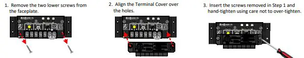
| BATTERY SET POINTS | ||||
| Set Point | Sealed | Flooded | ||
| 12-volt | 24-volt | 12-volt | 24-volt | |
| Absorption Voltage | 14.1 V | 28.2 V | 14.6 V | 29.2 V |
| Absorption Duration | 3 hours | |||
| Float Voltage | 13.7 V | 27.4 V | 13.7 V | 27.4 V |
| Time until Float | 3 hours | |||
| Equalize Voltage | N/A | 14.9 V | 29.8 V | |
| Equalize Duration (hours) | N/A | 3 hours | ||
| Equalize Calendar (days) | N/A | 28 days | ||
| Maximum Regulation Voltage* | 15.0 V | 30.0 V | 15.0 V | 30.0 V |
| Low Voltage Disconnect (LVD) | 11.5 V | 23.0 V | 11.5 V | 23.0 V |
| Low Voltage Reconnect (LVR) | 12.6 V | 25.2 V | 12.6 V | 25.2 V |
| High Voltage Disconnect (HVD) | 15.3 V | 30.6 V | 15.3 V | 30.6V |
| High Voltage Reconnect (HVR) | 14 V | 28 V | 14 V | 28 V |
| Startup LVD | 11.7 V | 23.4 V | 11.7 V | 23.4 V |
| Instant LVD | 10.0 V | 20.0 V | 10.0 V | 20.0 V |
| *Not temperature compensated. 15 V @ 12 V nominal, 30 V @ 24 V nominal. | ||||
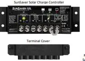
To Install the Terminal Cover (required by UL/ETL listed systems): Contact Information
Technical Support: Support.morningstarcorp.com Phone: 1‐215‐321‐4457


![Morningstar Sunsaver Mppt [ss-mppt-15l] User Manual](https://static-data1.manualsee.com/1/img/489/16528/2020/12/SS-MPPT-15L-1.jpg "Morningstar Sunsaver Mppt [ss-mppt-15l] User Manual")


