BAIcells Nova442i Outdoor 4x4W eNB
Product Information
The Nova442i is an outdoor base station manufactured by Baicells Technologies, Inc. It is a 4x4W eNB (evolved NodeB) that supports LTE (Long-Term Evolution) technology. The product comes with an installation guide that provides detailed instructions for safe and correct installation. The product has several LED indicators that show the status of various functions. The interface description and LED indicators are listed in Table 1-1 and Table 1-2 respectively. The product is subject to some restrictions when placed on the market, as indicated by the exclamation mark on the packaging. The disposal of electronic and electrical waste must be done responsibly and in compliance with the WEEE EU Directive. For any further information about the product, customers can contact Baicells Technologies Co., Ltd. through their website, phone, or email.
Product Usage Instructions
Before installing or powering on the base station, read all safety warnings provided in the user manual. If you have any questions or concerns, contact the Baicells support team. Ensure that the installation of the equipment complies with local and national electrical codes. The existing building or structure should provide short-circuit (overcurrent) protection rated no higher than 20A. Do not operate the wireless network device near unshielded blasting caps or in an explosive environment unless it has been modified and qualified for such use. To comply with the United States Federal Communications Commission (FCC) radio frequency (RF) exposure limits, antennas should be located at a minimum of 70 centimeters (27.6 inches) or more from the body of all persons. Refer to the installation instructions provided in the user manual before connecting the system to its power source. If you have any further questions or concerns about product usage, consult with a Baicells technical engineer or the support team.
About This Document
This document is a guide of Nova442i hardware installation for installation personnel, including the preparation of installation tools and supporting materials, the demands for installation environment, installation procedure, cable connection and power on.
Accomplish the installation of the device according to this guide, the installation personnel can avoid potential damage to the device during the installation procedure, which makes sure the subsequent good running of the device.
Copyright Notice
Baicells Technologies, Inc., copyrights the information in this document. No part of this document may be reproduced in any form or means without the prior written consent of Baicells Technologies, Inc. Refer to the “Contact Us” section below.
Disclaimer
The information in this document is subject to change at any time without notice. For more information, please consult with a Baicells technical engineer or the support team.
Disposal of Electronic and Electrical Waste
Pursuant to the WEEE EU Directive, electronic and electrical waste must not be disposed of with unsorted waste. Please contact your local recycling authority for disposal of this product.
Exclamation Mark
According to Article 10 (10) of Directive 2014/53/EU, the packaging shows that this radio equipment will be subject to some restrictions when placed on the market
Revision Record
| Date | Version | Description |
| 10 June, 2023 | 01 | Initial Released. |
Contact Us
| Baicells Technologies Co., Ltd. | Baicells Technologies North America, Inc. | |
| China | North America | |
| Address | 9-10F,1stBldg.,No.81BeiqingRoad,Haidian District,Beijing,China | 555 Republic Dr., #200, Plano, TX 75074, USA |
| Phone | 400-108-0167 | +1-888-502-5585 |
| [email protected] or | [email protected] or | |
| Website | www.Baicells.com | https://na.Baicells.com |
Safety Information
For the safety of installation personnel and for the protection of the equipment from damage, please read all safety warnings. If you have any questions concerning the warnings, before installing or powering on the base station contact the Baicells support team.
IMPORTANT SAFETY INSTRUCTIONS
This warning symbol means danger. You are in a situation that could cause bodily injury. Before you work on any equipment, be aware of the hazards involved with electrical circuitry and be familiar with standard practices for preventing accidents. Warning Read the installation instructions before you connect the system to its power source.
- Warning Installation of the equipment must comply with local and national electrical codes.
- Warning This product relies on the existing building or structure for short circuit ( protection. Ensure that the protective device is rated no greater than 20A.
- Warning Do not operate this wireless network device near unshielded blasting caps or i n an explosive environment unless the device has been modified and qualified for such use.
- Warning In order to comply with the United States Federal Communications Commission ( radio frequency ( exposure limits, antennas should be located at a min imum of 70 centimeters (27.6 inches) or more from the body of all persons.
Product Overview
Introduction
The Baicells Nova442i is an advanced two-carrier outdoor eNodeB (eNB) compliant with 3GPP LTE TDD technology. This 4x4W eNB operates in Carrier Aggregation (CA) mode or Dual Carrier (DC) mode. In CA mode, Nova442i supports 2CC (2 component carriers) DL/UL CA. 2CC DL/UL CA doubles DL/UL peak throughput comparing to that of a single carrier. By aggregating 2 separated spectrum resources into a virtual contiguous spectrum resource. In DC mode, each carrier is treated as an independent cell, supporting 96+96 users, with each cell supporting 5, 10, 15, or 20MHz bandwidth. Using a Nova442i in DC mode simplifies and streamlines the deployment of split sectors. In addition, HaloB (an embedded EPC option) is available on the Nova442i as part of the base software. The Baicells patented HaloB solution migrates the necessary core network functions to the eNB.
Highlights
Following are some of the key Nova442i highlights.
- Standard LTE TDD Band 48
- GUI-based local and remote Web management
- Excellent Non-Line-of-Sight (NLOS) coverage
- Peak rate: Up to DL 290Mbps and UL 70Mbps with 2x20MHz bandwidth
- 2CC DL/UL CA improves the spectrum efficiency of fragmented spectrum resources.
- Suitable for private and public deployments; any IP based backhaul can be used, including public transmission protected by Internet Protocol Security (IPsec)
- 96 RRC connected users per carrier (96+96 in DC mode); upgradeable to higher capacity in future releases
- Built-in RF antenna and GPS antenna
- Integrated small cell form factor for quick and easy installation
- Configured out of the box to work with Baicells Cloud Core
- HaloB as embedded EPC solution
- Supports Transparent Bridge Mode
- Supports Citizens Broadband Radio Service (CBRS)
- Plug-and-play with Self-Organizing Network (SON) capabilities
- Inter operation with all standard LTE Evolved Packet Core (EPC)
- Supports TR-069 network management interface
- Lower power consumption, which reduces OPEX, can be powered easily by Baicells compact outdoor smart UPS
Appearance
The Nova442i eNB appearance is shown in Figure 1-1.
 The Nova442i interfaces and LED indicators are shown in Figure 1-2.
Figure 1-2 Nova442i Interfaces and LED Indicators 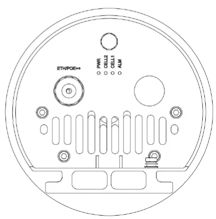
The Nova442i interfaces are described in Table 1-1.
Table 1-1 Nova442i Interface Description
| Interface | Description |
| ETH/POE++ | RJ-45 interface (FE/GE) Used for power supply, debug or data backhaul. PoE++, complied with IEEE 802.3bt standard |
The Nova442i interface indicators are described in Table 1-2.
Table 1-2 Nova442i LED Indicators
| Identity | Color | Status | Description |
| PWR | Green | Steady On | Power On |
| OFF | No Power Supply | ||
| CELL2 | Green | Fast flash: 0.125s on,0.125s off | CELL 2 inactivated |
| Slow flash: 1s on,1s off | CELL 2 activated | ||
| CELL1 | Green | Fast flash: 0.125s on,0.125s off | CELL 1 inactivated |
| Slow flash: 1s on,1s off | CELL 1 activated | ||
| ALM | Red | Steady On | Hardware alarm, e.g., VSWR alarm |
| OFF | No alarm |
Technical Specification
Technology
| Item | Description |
| Standard | LTE TDD RAN (3GPP R15 compliant) |
| TDD UL/DL Configuration | 1, 2, 6 (with Special subframe configuration 7) |
| Model No. | mBS31010 |
| Frequency Band | Band48 (3550 MHz – 3700 MHz) |
| Channel Bandwidth | SC: 10/20 MHz CA: 40 MHz as maximum aggravated bandwidth |
| Multiplexing | MIMO: 2×2 (DL) |
| Security | Radio: SNOW 3G/AES-128 Backhaul: IPsec (X.509 AES-128, AES-256, SHA-128, SHA-256) |
Interface
| Item | Description |
| Ethernet Interface | 1 RJ-45 Ethernet interface (1 GE) |
| Power Supply | PoE++, IEEE 802.3bt standard |
| Protocols Used | IPv4/IPv6 (Dual Stack), UDP, TCP, ICMP, SNMPv2c, NTP, SSH, IPsec, TR-069, HTTP/HTTPs, 1588v2, DHCP |
| Network Management | IPv4/IPv6, HTTP/HTTPs, SNMPv2c, TR-069, SSH, Embedded EPC |
| VLAN/VxLAN | 802.IQ/VxLAN |
| LED Indicators | 4 x status LED CELL1/CELL2/ALM/PWR |
Performance
| Item | Description | ||
| Peak Data Rate (DC) | 2×20 MHz | DL (Mbps) | UL (Mbps) |
| UL/DL Config 1 | 2×10⁵ | 2×28 | |
| UL/DL Config 2 | 2×145 | 2×14 | |
| UL/DL Config 6 | 2×85 | 2×35 | |
| 2×10 MHz | DL (Mbps) | UL (Mbps) | |
| Item | Description | ||||
| UL/DL Config 1 | 2×51 | 2×14 | |||
| UL/DL Config 2 | 2×70 | 2×7 | |||
| UL/DL Config 6 | 2×42 | 2×17 | |||
| Peak Data Rate (CA) | 2×20 MHz | DL (Mbps) | UL (Mbps) | ||
| UL/DL Config 1 | 210 | 56 | |||
| UL/DL Config 2 | 290 | 28 | |||
| UL/DL Config 6 | 170 | 70 | |||
| 2×10 MHz | DL (Mbps) | UL (Mbps) | |||
| UL/DL Config 1 | 102 | 28 | |||
| UL/DL Config 2 | 140 | 14 | |||
| UL/DL Config 6 | 84 | 34 | |||
| 20MHz + 10MHz | DL (Mbps) | UL (Mbps) | |||
| UL/DL Config 1 | 156 | 42 | |||
| UL/DL Config 2 | 215 | 21 | |||
| UL/DL Config 6 | 127 | 52 | |||
| User Capacity | Up to 96 RRC connected users per cell (4 users per TTI) Ÿ SC/CA: 96 RRC connected users Ÿ DC: 96+96 RRC connected users | ||||
| Maximum Deployment Range | 12 kilometers | ||||
| Latency | 30 milliseconds | ||||
| Receive Sensitivity | -100 dBm (per channel) | ||||
| Modulation | MCS0 (QPSK) to MCS27 (256QAM) DL: QPSK, 16QAM, 64QAM, 256QAM UL: QPSK, 16QAM, 64QAM | ||||
| Transmit Power Range | 0 to 36 dBm per channel (combined +42dBm, configurable) (1 dB interval) | ||||
| Quality of Service | Nine-level priority indicated by QoS Class Identifiers (QCI) | ||||
| ARQ/HARQ | Supported | ||||
| Synchronization | GPS, 1588v2 | ||||
NOTE The test method of r eceiving sensitivity is proposed by the 3GPP TS 36.104 , which is based on 5MHz bandwidth, FRC A1 3 in Annex A.1 QPSK R=1/3 , 25RB standard.
Modulation Levels (Adaptive)
| MCS | Modulation Scheme | RSRP (dBm) | Coverage Distance (km) |
| 0 – 4 | QPSK | -120 ≤ RSRP < -110 | 9 < D ≤ 12 |
| 5- 9 | 16QAM | -110 ≤ RSRP < -100 | 4 < D ≤9 |
| MCS | Modulation Scheme | RSRP (dBm) | Coverage Distance (km) | ||
| 10 – 19 | 64QAM | -100 ≤RSRP < -85 | 2 < D ≤ 4 | ||
| 20 – 27 | 256QAM | RSRP ≥ -85 | D ≤ 2 |
NOTE
The information provided is for reference only as the environment can impact modulation levels. S cenario: Base Station height is 3 0 meters ; Customer U ser E quipment (CPE height is two meters.
Features
| Item | Description |
| Voice | VoLTE* |
| NSA | Supported |
| SON | Self-Organizing Network Ÿ Automatic setup Ÿ Automatic Neighbor Relation (ANR) Ÿ PCI confliction detection |
| EPC | HaloB (Embedded EPC) |
| Traffic Offload | Local breakout |
| Layer 2 Support | Transparent Bridge Mode |
| Maintenance | Ÿ Local/Remote Web maintenance Ÿ Online status management Ÿ Performance statistics Ÿ Fault management Ÿ Local/Remote software upgrade Ÿ Logging Ÿ Connectivity diagnosis Ÿ Automatic start and configuration Ÿ Alarm reporting Ÿ User information tracing Ÿ Signaling trace |
- Planned for future release
Link Budget
| Item | Description |
| RF Antenna | Internal 4T4R omni high-gain antenna Ÿ Horizontal Beam width 360° Ÿ Vertical Beam width 7.5° Ÿ Polarization: ±45° |
| GPS Antenna | Internal GPS antenna |
| Antenna Gain | 12dBi |
| Item | Description | ||
| Power Control | UL Open-loop/Closed-loop Power Control, DL Power Allocation (3GPP TS 36.213 compliant) |
Physical
| Item | Description |
| Surge Suppression | Yes |
| Power Interface Lightning Protection | Differential mode: ±10 KA Common mode: ±20 KA |
| MTBF | ≥ 150000 hours |
| MTTR | ≤ 1 hour |
| Ingress Protection Rating | IP55 |
| Operating Temperature | -40°F to 131°F / -40°C to 55°C |
| Storage Temperature | -49°F to 158°F / -45°C to 70°C |
| Humidity | 5% to 95% RH |
| Atmospheric Pressure | 70 kPa to 106 kPa |
| Power Consumption | Typical 70W, maximum 90W |
| Weight | 21.2 lbs / 9.6 kg |
|
Dimensions (HxWxD) | Diameter: 7.9 inches/200mm Height: with lightning rod: 33.7 inches/857mm without lightning rod: 23.9 inches/608mm |
| Installation | Pole mount |
FCC Compliance
This device complies with part 15 of the FCC Rules. Operation is subject to the following two conditions: ( This device may not cause harmful interference, and ( this device must accept any interference received, including interference that may cause undesired operation. Any Changes or modifications not expressly approved by the party responsible for compliance could void the user’s authority to operate the equipment This equipment has been tested and found to co mply with the limits for a Class A digital device, pursuant to part 15 of the FCC Rules. These limits are designed to provide reasonable protection against harmful interference when the equipment is operated in a commercial environment. This equipment gene rates, uses, and can radiate radio frequency energy and, if not installed and used in accordance with the instruction manual, may cause harmful interference to radio communications. Operation of this equipment in a residential area is likely to cause harmful interference in which case the user will be required to correct the interference at his own expense.
Warning
This equipment complies with FCC radiation exposure limits set forth for an uncontrolled environment. This equipment should be installed and ope rated with minimum distance 1 0 0 c m between the radiator your body.
Installation Preparation
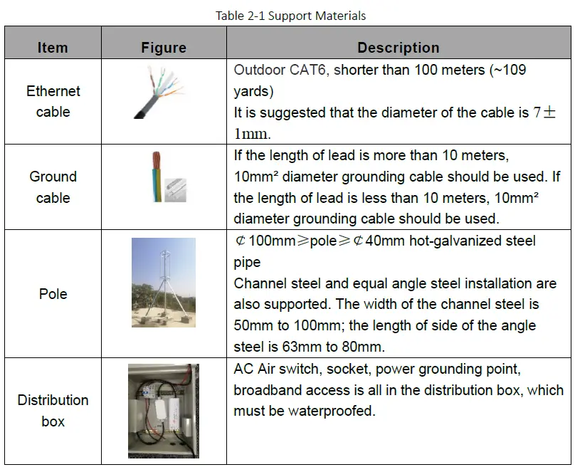
Support Materials
In addition to industry standard tools, you will need the materials described in Table 2-1 during the installation. When selecting an RF antenna, be sure to match the frequency range of the antenna with the eNB.
Installation Tools
The following tools are needed during the installation. 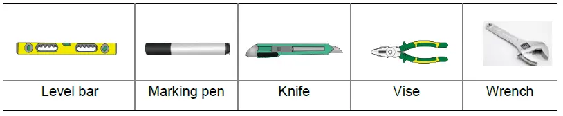

Installation Environment al Requirements
In addition to network planning, when determining where to place the eNB you need to consider factors such as climate, hydrology, geology, the possibility of earthquakes, reliable electric power, and transportation access. Avoid locating the eNB in areas w here there may be extreme temperatures, harmful gases, unstable voltages, volatile vibrations, loud noises, flames, explosives, or electromagnetic interference (e.g., large radar stations, transformer substations). Avoid areas prone to impounded water, soa king, leakage, or condensation. Table 2 2 provides typical environmental specifications for this eNB.
Table 2 2 Environmental R equirements
| Item | Range | Typical value |
| Temperature | -40°C to 55°C | 25°C |
| Relative humidity (no condensation) | 0% to 100% | 5% to 95% |
| Safety voltage | 42V to 58V | 48V |
Personnel Requirements
The installation personnel must master the basic safe operation knowledge, through the training, and having th e corresponding qualifications.
Lightening & Grounding Protection
You must protect the eNB, antenna, and GPS against lightning. Following are guidelines concerning grounding.
- The yellow g reen ground wire must be at least 1 0 mm 2 in diameter.
- In principle, always place the grounding as near as possible to the equipment.
- Connect to a reliable outdoor grounding point (earth) using one ground screw.
- The connection of the grounding points and gro und bar need to be tight and reliable. Rustproofing the terminals, e.g., with anti oxidant coating or grease, is required.
Installation
Unpacking
Before opening the box, make sure the package is in good condition, undamaged and not wet. During the unpacking, avoid potential damaging impacts from hits or excessive force. Once unpacked, check whether the quantity is consistent with the packing list.
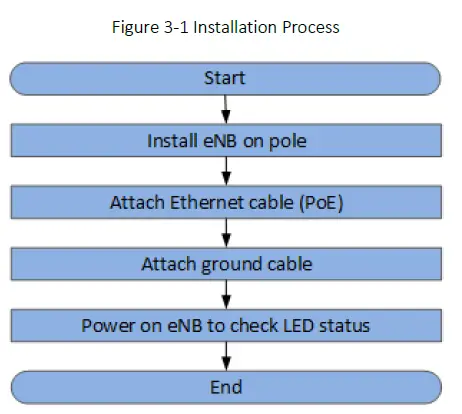
Installation Procedure
Figure 3-1 provides an overview of the installation process.
Figure 3-1 Installation Process
Install on Pole
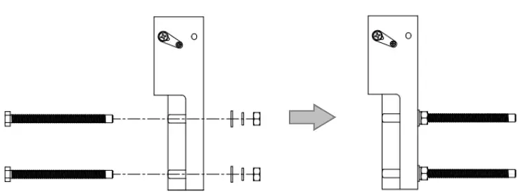
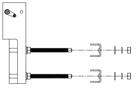
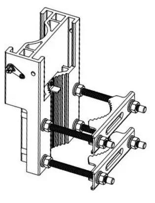
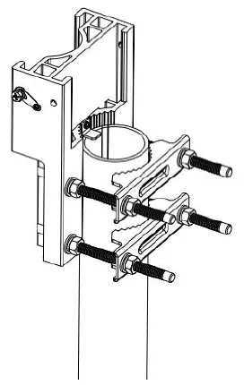
The eNB mounting bracket is assembled in manufacturing before packing. The only action required by the installer is to fix the assembly on the pole. Check to ensure the diameter of the pole is in the range of 2.4 inches to 3.9 inches (60mm to 100 mm). The position of the gNB on the pole should be at least 47 inches (120 cm) in height. Follow the steps below to install the eNB on a pole.
- Assemble the mounting bracket.
- Insert four M10 bolts on the mounting bracket, and fasten with flat washers, spring washers and hex nuts.

- Assemble two clamps on M10 bolts, and fasten with flat washers, spring washers and hex nuts. The reserved distance to the mounting bracket is approximately the diameter of the pole. Hex nuts do not need to be fasten.

- The mounting bracket assembling is complete.

- Insert four M10 bolts on the mounting bracket, and fasten with flat washers, spring washers and hex nuts.
- Put the assembled mounting bracket from the top of the pole. Adjust the position of clamps and fasten hex nuts.

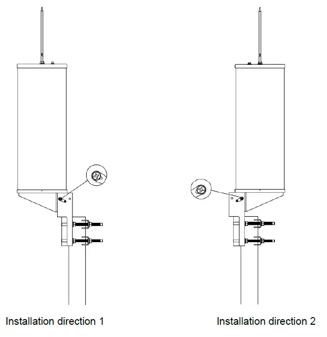
- Put the eNB from up to down to the b ottom, fasten wit h the M6 captive screw s on both sides of the bracket. Two installation directions are supported.

Connect Cable
Cable Laying Requirements
General requirements
- Bending radius of feeder cable: 7/8” > 250mm, 4/5” > 380mm.
- Bending radius of jumper cable: 1/4” > 35mm, 1/2” (super soft) > 50mm, 1/2” (ordinary) > 127mm.
- Bending radius of power cable and grounding cable: > tripled of the diameter of the cable.
- The minimum bend radius of the optical fiber is the 20 times the diameter of the optical fiber.
- Bind the cables according the type of the cable, intertwining and crossing are forbidden.
- An identification label should be attached after the cable is laid.
Grounding laying requirements
- The grounding cable must connect to the grounding point.
- The grounding cable must be separate with the signal cables, of enough distance to avoid signal interference.
Connect Ethernet Cable
- Connect the Ethernet cable to ETH/POE++ interface. The connector is a PG connector, it is self-waterproofed.
- The Ethernet cable connect to the PoE interface of the PoE adaptor.
- The LAN interface of the PoE adaptor connect to a LAN switch or a router for maintenance and backhaul.
NOTE: The PoE adaptor must be placed in the distribution box for waterproof.
Connect Ground Cable
Pole Grounding
The purpose of the pole grounding is to protect the equipment in the station from the damage of lightning overvoltage as far as possible. However, the interfaces between the eNB and the outside world mainly include power system, grounding system, antenna feeder and lightning receiving device, and signal line. Therefore, the damage caused by lightning mainly comes from the voltage difference between the equipment in the eNB and one or more of the four interfaces. The pole grounding is shown in Figure 3-2.
Figure 3-2 Pole Grounding
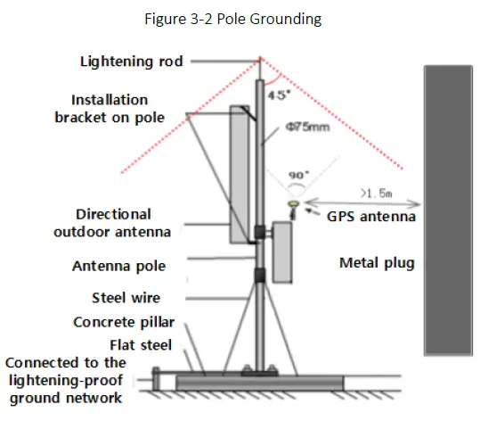
- The installation position of the grounding bar shall meet the design requirements. The holding pole and tower body must be connected to the lightning protection network or grounded with a separate lead.
- The diameter of the grounding wire meets the design requirements. The copper nose must be used for grounding, and the grounding resistance is required to be less than 10 ohms. If the resistance of the public network communication equipment placed in other systems is less than 10 ohms, the grounding network of the system should be overlapped.
- The grounding wire must be the whole wire material. When laying, it should be bound separately with other cables. All grounding wires should be fixed with wire code or binding tape with a fixed spacing of 0.3m. The appearance should be straight and beautiful.
- The copper bar must be used for the grounding bar, and the specification of the grounding bar shall meet the design requirements. If there are no specific requirements in the design, 300 × 40 × 4mm and fixed with expansion bolts.
- The grounding wire must be made of the whole cable material, the intermediate joint is strictly prohibited, and the excess length should be cut. The skin shall be complete, and the insulation resistance of the core wire to the ground (or metal isolation layer) shall meet the technical requirements of the cable.
- The grounding wire shall be connected to the integrated grounding bar of the building. If it is impossible to connect to the integrated grounding bar of the building, the appropriate grounding point can be selected according to the integrated grounding situation of the indoor building. The selection of grounding point must be higher than the grounding grid, and the feeder grounding shall be towards the downward direction of the feeder, never upward.
- The grounding electrode of the self-built grounding grid for the outdoor antenna of the tunnel must meet the design requirements. The buried depth of the grounding electrode and the welding quality of the flat iron meet the specification requirements. In principle, the buried depth of the grounding electrode shall not be less than 0.7m. The non-self-built grounding network shall be connected to the grounding network of the owner.
- The eNB grounding, power adapter grounding, distribution box grounding and feeder grounding must be connected to the grounding bar independently, and the grounding bar must have a path from the lead to the earth.
3.4.3.2 eNB Grounding
Prepare the grounding cable according to the actual measurements and requirements of the specific installation site. The grounding screw is located on the bottom of the unit, as shown in Figure 3-3. Follow the steps below the figure to connect the ground cable.
Figure 3-3 Grounding Screws
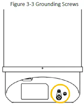
- Unscrew the grounding screw, connect one end of the ground cable to the grounding screw, and fasten it again.
- Once the eNB is installed at the outdoor location, the other end of the ground cable needs to connect to a good grounding point.
Power on to Check LED Status
Power on the eNB, and wait a few minutes while the eNB boots up. Per the previous Figure 1 2 and Table 1 2 in “ 1.3 Appearance ”, check that the LED indicators are lighting as expected.
FAQ
- After the device is connected with the power line, the PWR of the device will not be displayed when it is powered on.
- Maybe the power line is not connected well, and the contact is poor.
- There is no power in the circuit.
- Reverse connection of DC wire.
- The adapter does not work.
- Poor contact of equipment power interface.
- How to choose the position of holding pole in the roof
- Not near the edge.
- The position of non-bearing beam cannot be selected.
- Do not choose the side close to the barrier, you need to choose the most open position.
- The coverage of eNB signal is not ideal after opening
- Check if the power is full in the base station configuration.
- Check whether the equipment has standing wave alarm. If there is any alarm, please handle it in time.
- Check whether the RF frequency band of the equipment is consistent with that of the antenna.
- Check whether the dip angle planning of the base station is reasonable.
- Whether there is blocking in antenna coverage direct vision.
Appendix A Terminology & Acronym
| Acronym | Full Name |
| ANR | Automatic Neighbor Relations |
| ARQ | Automatic Repeat Request |
| CA | Carrier Aggregation |
| CC | Component Carriers |
| CSFB | Circuit Switched Fallback |
| DC | Dual Carrier |
| EPC | Evolved Packet Core network |
| GPS | Global Positioning System |
| HARQ | Hybrid Automatic Repeat Request |
| IPsec | Internet Protocol Security |
| MIMO | Multi Input Multi Output |
| MME | Mobility Management Entity |
| MOCN | Multi-Operator Core Network |
| OPEX | Operating Expense |
| PAP | Password Authentication Protocol |
| PCI | Physical Cell Identifier |
| PLMN | Public Land Mobile Network |
| QAM | Quadrature Amplitude Modulation |
| QCI | QoS Class Identifiers |
| QoS | Quality of Service |
| QPSK | Quadrature Phase Shift Keying |
| RSRP | Reference Signal Receiving Power |
| SSH | Secure Shell |
| SON | Self-Organized Network |
| TAC | Tracking Area Code |


