![]()
Nova430i
Outdoor 4x250mW eNodeB
Quick Guide
Product Overview
1.1 Introduction
Baicells Nova430i is an advanced two-carrier outdoor eNodeB based on LTE TDD technology, which is developed by Baicells. It is capable of operating in Carrier Aggregation (CA) or Dual Carrier (DC) mode. In CA mode, contiguous or non-contiguous channels are aggregated to provide up to 40 MHz bandwidth. This essentially doubles the downlink capacity when the CA 430i is used with all CAT6/7 user equipment. In DC mode, each carrier is treated as an independent cell, supporting 96+96 users, and each supporting 5, 10, 15, or 20 MHz bandwidth. Using a Nova430i in DC mode simplifies and streamlines the deployment of split sectors. In addition to having the option to operate Nova430i in either CA or DC mode, HaloB (an embedded MME option) comes as a default feature in the base software. Baicells’s patented HaloB solution migrates the necessary core network functions to the and.
1.2 Features
- Compact, all-in-one design of internal antenna and integrated GPS
- Citizens Broadband Radio Service (CBRS) band covers with dual carrier.
- Based on 3GPP international standard TDD LTE technology; provide high-speed data service; support a maximum aggregation peak rate of DL: 220Mbit/s, UL: 14Mbit/s with 2x20MHz spectrum, using CAT 6/7 or higher users.
- Support flexible uplink and downlink time slot ratio: 1(2:2), 2(1:3), and high-speed data transmission.
- Support 5MHz/10MHz/15MHz/20MHz operation bandwidth.
- 96 concurrent users per carrier, 96+96 in DC mode.
- Support copper (RJ-45) backhaul, flexible to deploy.
- PoE++ power supply, only one Ethernet cable is required for data transmission and power supply.
- Security services to provide timely protection against potential security risks and illegal intrusion.
- Support simple and convenient local and remote web management.
- Integration as required, easy to install and deploy, accurate coverage, and improved network capacity.
- Support network management functions, which include management, monitoring, and maintenance.
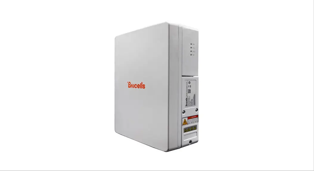
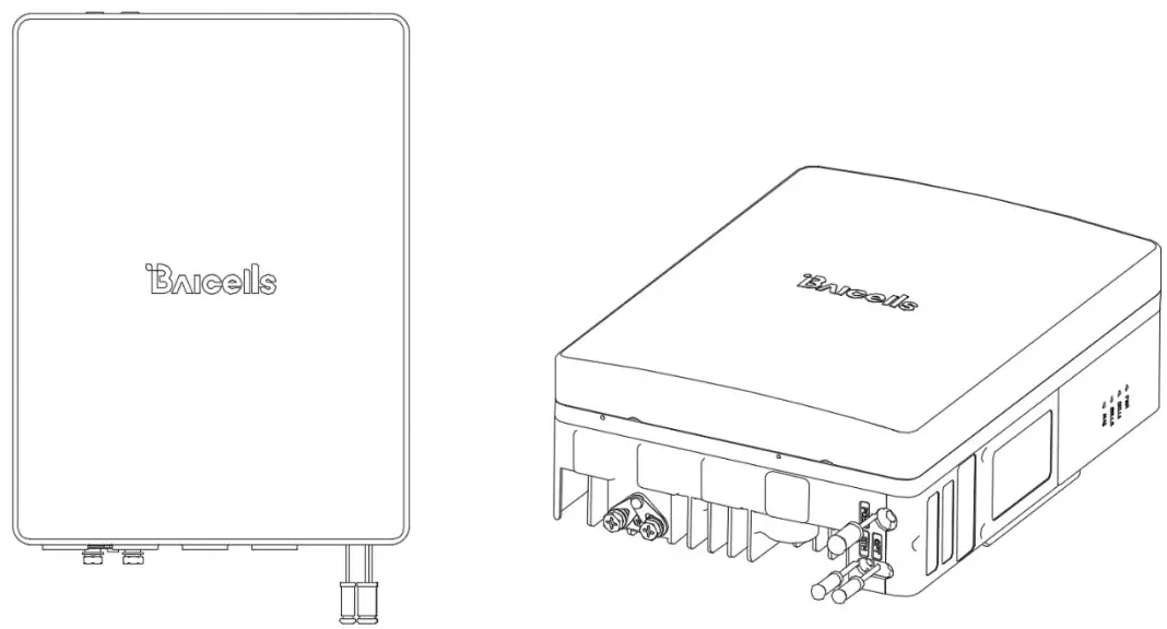
1.3 Appearance The Nova430i interfaces are described in Table 1-1.
Table 1-1 Nova430i Interface Description
 The Nova430i interfaces are described in Table 1-1.
| Interface Name | Description |
| ETH | RJ-45 interface (FE/GE) Used for power supply, debug, or data backhaul. PoE++, complied with IEEE 802.3bt standard |
| OPT | Reserved optical interface. |
The Nova430i interface indicators are described in Table 1-2.
Table 1-2 Nova430i Interface Indicators
Identity | Color | Status | Description |
| PWR | Green | Steady On | Power on |
| OFF | No power supply | ||
| CELL1 | Green | OFF | CELL1 is inactivated. |
| Fast flash: 0.1s on,0.1s off | CELL1 is deactivated. | ||
| Slow flash: 1s on,1s off | CELL1 is inactivated. | ||
| CELL2 | Green | OFF | CELL2 is inactivated. |
| Fast flash: 0.1s on,0.1s off | CELL2 is in deactivated. |
| Identity | Color | Status | Description |
| Slow flash: ls on,1 s off | CELL2 is inactivated. | ||
| ALM | Red | Steady On | Hardware alarm |
| OFF | No alarm |
1.4 Technical Specification
1.4.1 Hardware Specification
| Item | Description |
| LTE Mode | LTE TDD |
| LTE Frequency | Band48, and partial band42,band43 |
| Channel Bandwidth | 5MHz, 10MHz, 15MHz, 20MHz per carrier |
| Output Power | 24 dBm per antenna |
| Receive Sensitivity | -100 dBm |
| Synchronization | GPS |
| Backhaul | 1 RJ-45 Ethernet interface (1 FE/GE) |
| MIMO | DL 2 x 2 on each carrier, 2 carriers |
| Dimension | 309mm(H) x 227mm(W) x 104mm(D) |
| Installation Type | Pole or wall mount |
| Antenna Type | Built-in 4 high-gain LTE antennas •Horizontal Beamwidth 65±10° •Vertical Beamwidth 17° •Polarization: ±45° |
| Antenna Gain | 13.5 ± 0.8 dB |
| Power Consumption | Typical 20W, MAX 25W |
| Power Supply | PoE++, comply with IEEE 802.3bt standard |
| Weight | 4.85kgs |
| MTBF | 150000 hours |
| MTTR | 5_ 1 hour |
NOTE: The test method of receiving sensitivity is proposed by the 3GPP TS 36.104, which is based on 5MHz bandwidth, FRC A1-3 in Annex A.1 (QPSK, R=1/3, 25RB) standard.
1.4.2 Global Part Numbers
| Model No. | Description |
| pBS3101S | Band48, 10MHz, 20MHz per carrier, DL 2 x 2 on each carrier, 2 carriers, Built-in antenna. |
1.4.3 Software Specification
| Item | Description | |
| LTE Standard | 3GPP Release 15 | |
| Peak Rate | DC | •2×20 MHz: SA1:DL 2×80 (160)Mbps, UL 2×28 (56)Mbps SA2:DL 2×110 (220)Mbps, UL 2×14 (28)Mbps •2x10MHz: SA1:DL 2×40 (80)Mbps, UL 2×14 (28)Mbps SA2:DL 2×55 (110)Mbps, UL 2×7 (14)Mbps |
| CA | •2×20 MHz: SA1:DL 160Mbps, UL 28Mbps SA2:DL 220Mbps, UL 14Mbps •2x10MHz: SA1:DL 80Mbps, UL 14Mbps SA2:DL 110Mbps, UL 7Mbps | |
| User Capacity | 96 concurrent users in single carrier mode 96+96 concurrent users in DC mode 96 concurrent users in CA mode | |
| QoS Control | 3GPP standard Quality of Service Class Identifier (QC!), support SC1 | |
| Modulation | UL: QPSK, 16QAM, 64QAM DL: QPSK, 16QAM, 64QAM | |
| Voice Solution | VoLTE | |
| Traffic Offload | Local breakout | |
| SON | Self-organizing network: •Automatic setup •Automatic Neighbor Relation (ANR) •PCI confliction detection | |
| Network Mgmt | TR-069, SNMP | |
| Maintenance | Support remote/local maintenance, based on SSH protocol | |
| Support online status management | ||
| Support performance statistics | ||
| Support failure management | ||
| Support configuration management | ||
| Support local or remote software upgrading and loading | ||
| Support log | ||
| Support connectivity diagnosis | ||
| Support automatic start and configuration | ||
| Support alarm reporting | ||
| Support user information tracing | ||
| Support signaling trace | ||
1.4.4 Environment Specification
| Item | Description |
| Operating Temperature | -40°C to 55°C |
| Storage Temperature | -50°C to 65°C |
| Humidity | 5% to 95% |
| Atmospheric Pressure | 70 kPa to 106 kPa |
| Ingress Protection Rating | IP66 |
| Power Interface Lightning Protection | Differential mode: ±10KA Common mode: ±20KA |
1.4.5 Regulatory Compliance
FCC Compliance
This device complies with part 15 of the FCC Rules. Operation is subject to the following two conditions: (1) This device may not cause harmful interference, and (2) this device
must accept any interference received, including interference that may cause undesired operation.
Any changes or modifications not expressly approved by the party responsible for compliance could void the user’s authority to operate the equipment.
This equipment has been tested and found to comply with the limits for a Class B digital device, pursuant to part 15 of the FCC Rules. These limits are designed to provide reasonable protection against harmful interference in a residential installation. This equipment generates uses and can radiate radio frequency energy and, if not installed and used in accordance with the instructions, may cause harmful interference to radio communications. However, there is no guarantee that interference will not occur in a particular installation. If this equipment does cause harmful interference to radio or television reception, which can be determined by turning the equipment off and on, the user is encouraged to try to correct the interference by one or more of the following measures:
- Reorient or relocate the receiving antenna.
- Increase the separation between the equipment and receiver.
- Connect the equipment into an outlet on a circuit different from that to which the receiver is connected.
- Consult the dealer or an experienced radio/TV technician for help.
Warning:
This equipment complies with FCC radiation exposure limits set forth for an uncontrolled environment. This equipment should be installed and operated with a minimum distance of 40cm between the radiator & your body.
Installation
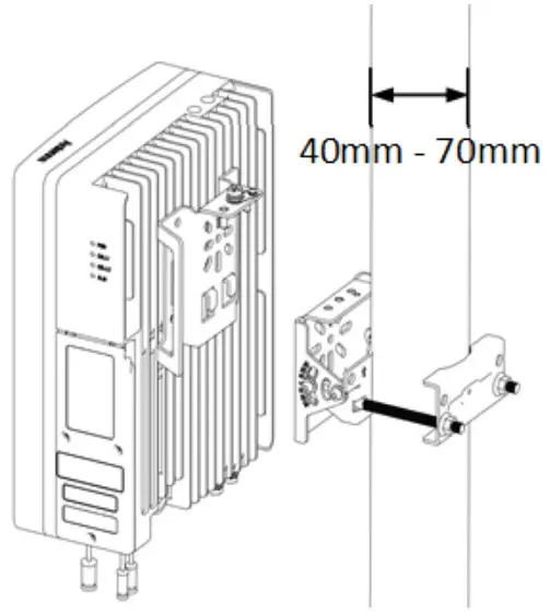
2.1 Install on Pole
The position of the eNB on the pole should be at least 47 inches (120 cm) in height.
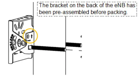 | 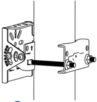 |
| Install the bracket on the pole. NOTE: the arrow must be upward. | Fasten two nuts on the back of the bracket. |
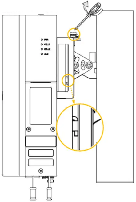
 | 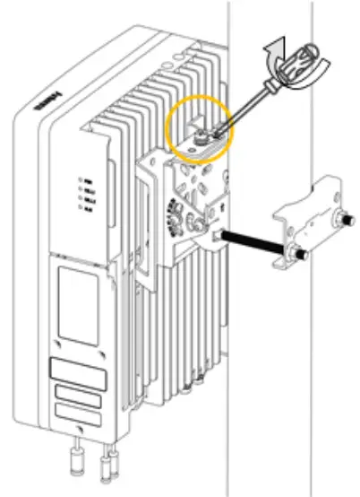 |
| From top to bottom, clip the end into the two hooks on the bracket. | Tighten the pin on the top of the bracket. |
After installation, adjust the eNB to a proper angle by adjusting the adjustable bracket.
2.2 Install on Wall
NOTE: The wall must bear at least 4 times the weight of the eNB.
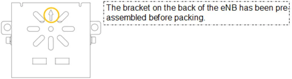 | 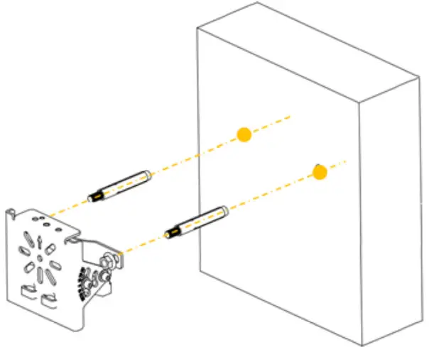 |  |
| Fit the installation bracket on the wall and mark drilling locations with a marker pen. NOTE: the arrow must be upward. | Install the bracket on the wall with expansion pipes. | From top to bottom, clip the end into the two hooks on the bracket and tighten the pin on the top of the bracket. |
2.3 Connect Cables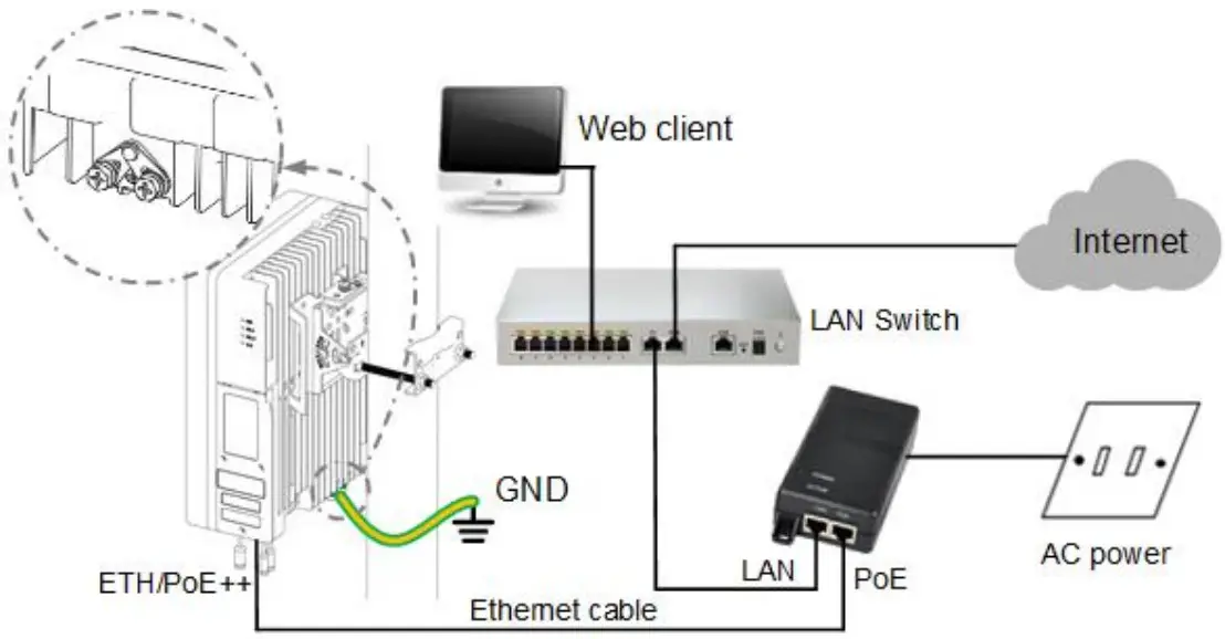 Power on the end, and wait a few minutes while the B boots up. Per the previous Table 1-1 and Table 1-2 in “1.3 Appearance”, check that the LED indicators are lighting
as expected.


