Baicells Nova846 Outdoor 8x5W eNodeB User Guide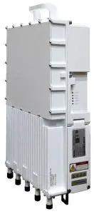
Product Overview
Introduction
The Baicells Nova846 is an advanced dual-mode outdoor integrated eNodeB (eNB) product that operates in LTE Time Division Duplexing (TDD) mode. This 8x5W eNB is capable of operating in Carrier Aggregation (CA) mode or Dual Carrier (DC) / split mode. Combining a variety of technologies, the Nova846 provides wireless coverage solutions, which will offer users with high-speed broadband wireless Internet access. It also can help operators improve outdoor coverage, enhance network capacity, eliminate blind spots and improve cell edge rates.
In CA mode, contiguous or non-contiguous channels are aggregated to provide up to 40 MHz bandwidth. This essentially doubles the downlink capacity when the CA mode is used with all CAT6/7/15 user equipment. In DC mode, each carrier is treated as an independent cell, supporting 128+128 users, and each supporting 20 MHz bandwidth. Using a Nova846 in DC mode simplifies and streamlines the deployment of split sectors.
In addition to having the option to operate Nova846 in either CA or DC mode, HaloB (an embedded MME option) comes as a default feature in the base software. Baicells’s patented HaloB solution migrates the necessary core network functions to the eNB.
The Nova846 can be widely used by telecom operators, broadband operators, and enterprises, etc.
Features
- Standard LTE TDD Bands 41,48.
- Support 5MHz/10MHz/15MHz/20MHz operation bandwidth.
- Peak rate (up to): DL 440 Mbps with 4×4 MIMO Carrier Aggregation (CA) mode, UL 28 (56) Mbps.
- 128+128 concurrent users, 256+256 RRC users.
- Support GPS synchronization.
- Supports Citizens Broadband Radio Service (CBRS).
- Embedded HaloB (“lite” EPC) solution.
- Lower power consumption, which reduces OPEX, can be powered easily by Baicells compact outdoor Smart UPS EPB series.
- Plug-and-play with self-organizing network (SON) capabilities.
- IoT with all standard LTE Evolved Packet Core (EPC).
- GUI-based local and remote web management, cooperating with the BaiOMC NMS to support unified configuration, management, monitoring and maintenance.
- Highly secured with equipment certification against potential intrusion risk.
- TR-069 network management interface support.
- Security services to provide timely protection against potential security risks and illegal intrusion.
- Integration as required, easy to installation and deployment, accurate coverage and improved network capacity.
Appearance
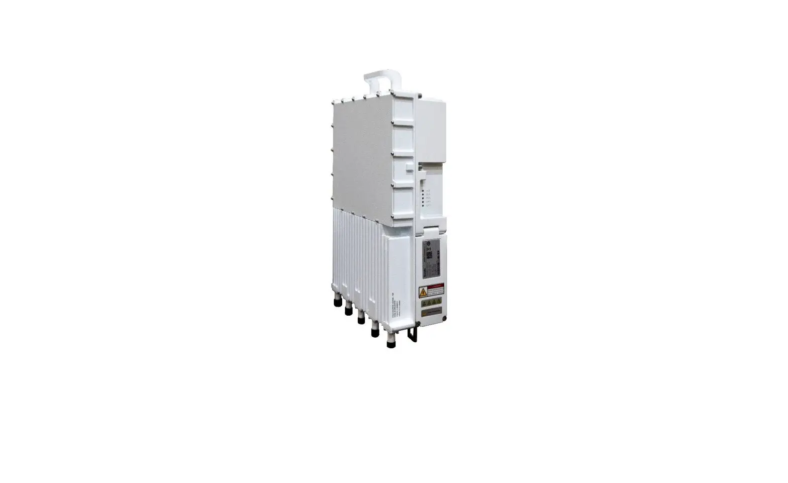
The appearance of Nova846 is shown in Figure 1-1.
Figure 1-1 Nova846 Appearance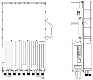
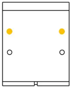
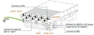
The interfaces and indicators Nova846 are shown in Figure 1-2.
Figure 1-2 Nova846 Interfaces and Indicators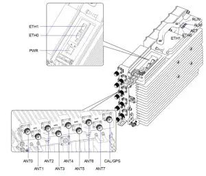
The Nova846 interfaces are described in Table 1-1.
| Interface | Description |
| ETH0 | Ethernet interface 1 (SFP optical interface or GE electric interface), connect to external transmission network, used for data backhaul. |
| ETH1 | Ethernet interface 2 (SFP optical interface), connect to external transmission network, used for data backhaul. |
| PWR | Power interface: -48V (-40.5V to 57V) DC |
| ANT0~ANT7 | Connect to external antenna 0 to antenna 7, N-type connector. |
| CAL/GPS | CAL is used for antenna phase alignment. GPS is used to connect to external GPS antenna, N-type connector. |
Table 1-2 Nova846 Interface Indicators
| Identity | Color | Status | Description |
| RUN | Green | Steady On | Power on |
| OFF | No power supply | ||
| ALM | Red | OFF | No alarm |
| Steady On | The system exists alarms. | ||
| ACT | Green | Steady On | The device has been powered on. |
| Fast flash: 0.125s on,0.125s off | Data is transmitting. | ||
| Slow flash: 1s on,1s off | The cell has been activated. | ||
| ETH0 | Green | Steady On | S1 link is up. |
| OFF | SFP module is out of place, Ethernet cable is out of place, power of the optical module is powered off, or S1 link is down. | ||
| ETH1 | Green | Steady On | S1 link is up. |
| OFF | SFP module is out of place, Ethernet cable is out of place, power of the optical module is powered off, or S1 link is down. |
Technical Specification
Hardware Specification
| Item | Description |
| LTE Mode | TDD |
| RF Standard | 3GPP 38.104 / Category B |
| LTE Bands | 41, 48 |
| Channel Bandwidth | 5MHz, 10MHz, 15MHz, 20MHz |
| Carrier Config. | Maximum 2 carriers |
| MAX Output Power | 37 dBm / channel x 8 channel |
| MIMO | DL 4×4 |
| Receive Sensitivity | -102 dBm |
| Synchronization | GPS |
| Data Interface | 1 x optical SFP + 1 x electrical GE or 2 x optical SFPs |
| Dimension | 432mm (H) x 280mm (W) x 118mm (D) |
| Installation Type | Pole or wall mount |
| Antenna Port | 8T8R |
| Antenna | External high-gain antenna, N-type connector External GPS antenna, N-type connector |
| Item | Description |
| Power consumption | ≤ 300W |
| Power | +40.5V to 57 V DC, Nominal +54VDC |
| Weight | 11.0kgs |
| Basic report function | RSSI , VSWR, TSSI(transmission signal strength), temperature, etc. |
| Cooling Method | Natural convection cooling @ vertical installation |
| Noise Figure | Room temperature: <2.5 All temperature: <3.5 |
| MTBF | ≥ 150000 hours |
| MTTR | ≤ 1 hour |
NOTE: The test method of receiving sensitivity is proposed by the 3GPP TS 36.104, which is based on 5MHz bandwidth, FRC A1-3 in Annex A.1 (QPSK, R=1/3, 25RB) standard.
Global Part Numbers
| Model No. | Description |
| sBS71040 | Band41, 10MHz, 20MHz per carrier, DL 4 x 4 on each carrier, 2 carriers. |
Software Specification
| Item | Description | |
| LTE Standard | 3GPP Release 15 | |
| Peak Rate | CA mode | 2×20 MHz: SA1: DL 320Mbps, UL 28 (56)Mbps SA2: DL 440Mbps, UL 14 (28)Mbps 2x10MHz: SA1: DL 160Mbps, UL 14 (28)Mbps SA2: DL 220Mbps, UL 7 (14)Mbps |
| Single carrier | 20 MHz: SA1: DL 160Mbps, UL 28Mbps SA2: DL 220Mbps, UL 14Mbps 10MHz: SA1: DL 80Mbps, UL 14Mbps SA2: DL 110Mbps, UL 7Mbps | |
| User Capacity | 128+128 concurrent users 256+256 RRC users | |
| QoS Control | 3GPP standard Quality of Service Class Identifier (QCI) | |
| Modulation | UL: QPSK, 16QAM, 64QAM | |
| Item | Description |
| DL: QPSK, 16QAM, 64QAM, 256QAM* | |
| Voice Solution | VoLTE, Circuit Switched Fallback (CSFB)* |
| Traffic Offload | Local breakout |
| SON | Self-organizing network: · Automatic setup |
| RAN Sharing | Multi-Operator Core Network (MOCN)* |
| HaloB | Supported |
| Network Mgmt | TR-069 |
| Maintenance | Support remote/local maintenance |
| Support online status management | |
| Support performance statistics* | |
| Support failure management* | |
| Support configuration management | |
| Support local or remote software upgrading and loading | |
| Support log | |
| Support connectivity diagnosis | |
| Support self-start and self-configuration |
NOTE: Future software version will release.
| Item | Description |
| Operating Temperature | -40°C to 55°C |
| Humidity | 2% to 95% |
| Atmospheric Pressure | 70kPa to 106kPa |
| Ingress Protection Rating | IP66 |
| Power interface Lightning Protection | Differential mode: ±10 KA Common mode: ±20 KA |
Regulatory Compliance
FCC Compliance
This device complies with part 15 of the FCC Rules. Operation is subject to the following two conditions:
(1) This device may not cause harmful interference, and
(2) this device must accept any interference received, including interference that may cause undesired operation.
Any Changes or modifications not expressly approved by the party responsible for compliance could void the user’s authority to operate the equipment.
This equipment has been tested and found to comply with the limits for a Class B digital device, pursuant to part 15 of the FCC Rules. These limits are designed to provide reasonable protection against harmful interference in a residential installation. This equipment generates uses and can radiate radio frequency energy and, if not installed and used in accordance with the instructions, may cause harmful interference to radio communications. However, there is no guarantee that interference will not occur in a particular installation. If this equipment does cause harmful interference to radio or television reception, which can be determined by turning the equipment off and on, the user is encouraged to try to correct the interference by one or more of the following measures:
- Reorient or relocate the receiving antenna.
- Increase the separation between the equipment and receiver.
- Connect the equipment into an outlet on a circuit different from that to which the receiver is connected.
- Consult the dealer or an experienced radio/TV technician for help.
Warning:
This equipment complies with FCC radiation exposure limits set forth for an uncontrolled environment. This equipment should be installed and operated with minimum distance 500cm between the radiator & your body.
Installation
Installation Material
n addition to industry standard tools, you will need the materials described in Table 2-1 during the installation. When selecting an RF antenna, be sure to match the frequency range of the antenna with the eNB.
Table 2-1 Support Materials
| Item | Description |
| Power cord | The diameter of power cable must be AWG15 or greater (such as AWG14). And the length from the power adaptor’s DC end to the device must be shorter than 100 meters (~109 yards). |
| Power plug | The power plug connecting to the electricity supply. |
| Antenna RF cable | 50 ohm feeder |
| Optical fiber | Single mode optical fiber |
| Antenna | Omnidirectional, or directional antenna |
| Ground cable | The diameter of grounding cable must be 10mm2 or greater. |
Installation Tool
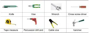
NOTE: Other accessories have been packed in the packing box.
Install GPS Antenna
Read the following GPS antenna installation requirements before installing it on the eNB.
- No major blocking from buildings in the vicinity. Make sure the space atop is at least 45 degrees unblocked by any buildings.
- Avoid installing the GPS antenna in the vicinity of any other transmitting and receiving devices, to avoid interference.
- The GPS antenna should be installed within 45 degrees to the lightning rod.
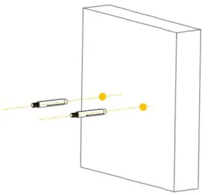
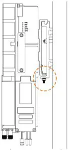
The GPS antenna system is assembled in manufacturing before packing. The only installation step is to fix the GPS mounting bracket on the eNB with the M4*14 screws (Figure 2-1).
Figure 2-1 GPS Antenna Installation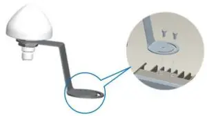
NOTE: The eNB may adopt different models of GPS antenna, so the GPS antenna may not the same as above figure. But the installation steps that fix it on the eNB is the same.
Weatherproofing
To protect the connection points from weather and climate, clean each connection point before installing cold shrink tubes, per the following figure.
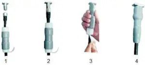
- Insert the cable into the cold shrink tube.
- Tighten the connector.
- Push the cold shrink tube to the top joint, and pull out the strip.
- Ensure the cold shrink tube is tightly fitted with the connection.
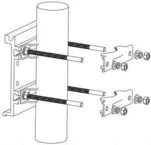
Install on Pole
Check to ensure the diameter of the pole is in the range of 1.6 inches to 3.9 inches (40mm to 100 mm). The position of the RRU on the pole should be at least 47 inches (120 cm) in height.
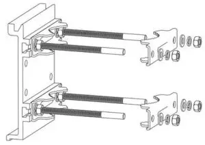
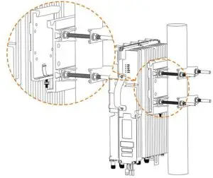
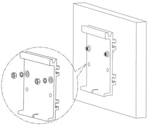
The brackets have been pre-assembled in manufacturing before packing. It includes two parts, one is pre-assembled on the back of the device. The other one is for pole mounting or wall mounting, as shown in Figure 2-2.
Figure 2-2 Pre-assembled Device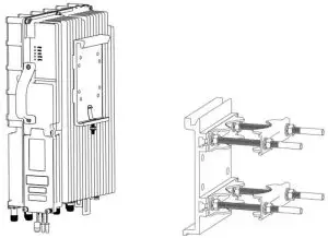
Following steps introduce how to fix the pre-assembled eNB on a pole.
- Take apart two clamps from the assembled bracket.

- Put the bracket against the pole and assemble two clamps back. Note that the sequence of flat washers, spring washers and nuts keeps the same with original.

- Fasten the pole bracket to ensure the bracket is firmly fixed on the pole.

- Hang the device (with bracket) on the pole bracket. Ensure bracket is firmly fixed on the pole. the screw on the bottom of the bracket clip into the groove on the pole bracket, and then fasten the screw.

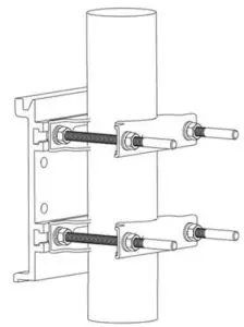
Install on Wall
Take apart assembly bracket first, only remains the wall bracket, as shown in Figure 2-3.
Figure 2-3 Wall Bracket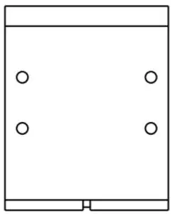
Following steps introduce how to fix the pre-assembled eNB on a wall.
- Put the wall bracket against the wall and mark two drilling locations with a marker pen.

- Drill two holes at the marked locations and install expansion bolts.

- Hang the wall bracket on expansion bolts, and fasten with flat washers, spring washers and nuts.
- Refer pole mount step to hang the device on the wall bracket.

Connect Cable
NOTE:
- According to the requirements of the site, both DC and AC power supply are provided to support different requirements of installation site. If DC power is selected, the power cable connects to the DC power supply directly. If AC power is selected, the power cable must connect to the AC power supply through a DC-AC adaptor.
- The antenna ports and CAL/GPS port must have waterproof protection.
Power On
Power on the eNB, and wait a few minutes while the eNB boots up. Per the previous figures, check that the LED indicators are lighting as expected.


