![]()
Nova430
Outdoor 4x250mW eNodeB
Quick Guide
P/N: 1701000177
Document version: 01
Product Overview
Introduction
Baicells Nova430 is an advanced two-carrier outdoor eNodeB based on LTE TDD technology, which is developed by Baicells. It is capable of operating in Carrier Aggregation (CA) or Dual Carrier (DC) mode/split mode.
In CA mode, contiguous or non-contiguous channels are aggregated to provide up to 40 MHz bandwidth. This essentially doubles the downlink capacity when the CA 430 is used with all CAT6/7 user equipment.
In DC mode, each carrier is treated as an independent cell, supporting 96+96 users, and each supporting 5, 10, 15, or 20 MHz bandwidth. Using a Nova430 in DC mode simplifies and streamlines the deployment of split sectors.
In addition to having the option to operate Nova430 in either CA or DC mode, HaloB (an embedded MME option) comes as a default feature in the base software. Baicells’spatented HaloB solution migrates the necessary core network functions to the and.
Features
- Citizens Broadband Radio Service (CBRS) band covers with the dual carrier.
- Peak rate: (up to) DL 220Mbit/s, UL2x28 (56) Mbit/s with 2x20MHz spectrum, using all Cat6/7 or higher UEs.
- Support flexible uplink and downlink time slot ratio: 1(2:2), 2(1:3), and high-speed data transmission.
- Support 5MHz/10MHz/15MHz/20MHz operation bandwidth.
- 96 concurrent users per carrier, 96+96 in DC mode.
- Support copper (RJ-45) backhaul, flexible to deploy.
- Integrated small cell form factor for quick and easy installation.
- Suitable for private and public deployments; any IP-based backhaul can be used, including public transmission protected by Internet Protocol Security (IPSec).
- Support PoE++ power supply, only one Ethernet cable is required for data transmission and power supply.
- Security services to provide timely protection against potential security risks and illegal intrusion.
- Support simple and convenient local and remote web management.
- Integration as required, easy to install and deploy, accurate coverage, and improved network capacity.
- Support network management functions, which include management, monitoring, and maintenance.
Appearance
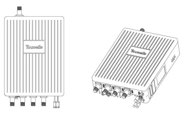
The Nova430 interfaces are described in Table 1-1.
Table 1-1 Nova430 Interface Description
| Interface Name | Description |
| ETH/POE | RJ-45 interface (FE/GE) Used for power supply, debug, or data backhaul. PoE++, complied with IEEE 802.3bt standard |
| GPS | GPS antenna interface, N-type connector |
| ANTO | External antenna interface 1, N-type connector |
| ANTI | External antenna interface 2, N-type connector |
| ANT2 | External antenna interface 3, N-type connector |
| ANT3 | External antenna interface 4, N-type connector |
The Nova430 interface indicators are described in Table 1-2.
Table 1-2 Nova430 Interface Indicators
| Identity | Color | Status | Description |
| PWR | Green | Steady On | Power on |
| OFF | No power supply | ||
| CELL1 | Green | OFF | CELL1 is inactivated. |
| Fast flash: 0.1s on,0.1s off | CELL1 is deactivated. | ||
| Slow flash: 1s on,1s off | CELL1 is inactivated. | ||
| CELL2 | Green | OFF | CELL2 is inactivated. |
| Fast flash: 0.1s on,0.1s off | CELL2 is deactivated. | ||
| Slow flash: 1s on,1s off | CELL2 is inactivated. | ||
| ALM | Red | Steady On | Hardware alarm |
| OFF | No alarm |
Technical Specification
Hardware Specification
| item | Description |
| LTE Mode | LTE TDD |
| LTE Frequency | Band48 |
| Channel Bandwidth | 5MHz, 10MHz, 15MHz, 20MHz per carrier |
| Output Power | 24 dBm per antenna |
| Receive Sensitivity | -100 dBm |
| Synchronization | GPS |
| Backhaul | 1 RJ-45 Ethernet interface (1 FE/GE) |
| MIMO | DL 2 x 2 on each carrier, 2 carriers |
| Dimension (HxWxD) | with joint: 381x 227 x 75 millimeters without joint and handle: 311 x 227 x 75 millimeters |
| Installation Type | Pole or wall mount |
| Antenna Type |
|
| Power Consumption | Typical 20W, MAX 25W |
| Power Supply | PoE++, comply with IEEE 802.3bt standard |
| Weight | 4.75kgs (with pre-installed bracket) 4.35kgs (without bracket) |
| MTBF | ≥ 150000 hours |
| MTTR | ≤ 1 hour |
NOTE: The test method of receiving sensitivity is proposed by the 3GPP TS 36.104, which is based on 5MHz bandwidth, FRC A1-3 in Annex A.1 (QPSK, R=1/3, 25RB) standard.
Global Part Numbers
| Model No. | Description |
| pBS3101SE | Band42/43/48, 10MHz, 20MHz per carrier, DL 2 x 2 on each carrier, 2 carriers. |
Software Specification
| Item | Description | |
| LTE Standard | 3GPP Release 15 | |
| Peak Rate | DC mode | · 2×20 MHz: SA1: DL 2x80Mbps, UL 2x28Mbps SA2: DL 2x110Mbps, UL 2x14Mbps· 2x10MHz: SA1: DL 2x40Mbps, UL 2x14Mbps SA2: DL 2x55Mbps, UL 2x7Mbps |
| CA mode | · 2×20 MHz: SA1: DL 160Mbps, UL 28Mbps SA2: DL 220Mbps, UL 14Mbps· 2x10MHz: SA1: DL 80Mbps, UL 14Mbps SA2: DL 110Mbps, UL 7Mbps | |
| User Capacity | 96 concurrent users in single carrier mode 96+96 concurrent users in DC mode 96 concurrent users in CA mode | |
| QoS Control | 3GPP standard Quality of Service Class Identifier (QCI), SC1 | |
| Modulation | UL: QPSK, 16QAM, 64QAM DL: QPSK, 16QAM, 64QAM | |
| Voice Solution | VoLTE (future software release) | |
| Traffic Offload | Local breakout | |
| SON | Self-organizing network: · Automatic setup| | |
| Network Mgmt. | TR-069, SNMP | |
| Maintenance | Support remote/local maintenance, based on SSH protocol | |
| Support online status management | ||
| Support performance statistics | ||
| Support failure management | ||
| Support configuration management | ||
| Support local or remote software upgrading and loading | ||
| Support log | ||
| Support connectivity diagnosis | ||
| Support automatic start and configuration | ||
| Support alarm reporting | ||
| Support user information tracing | ||
| Support signaling trace | ||
Environment Specification
| Item | Description |
| Operating Temperature | -40°C to 55°C |
| Storage Temperature | -50°C to 65°C |
| Humidity | 5% to 95% |
| Atmospheric Pressure | 70 kPa to 106 kPa |
| Ingress Protection Rating | IP65 |
| Power Interface Lightning Protection | Differential mode: ±10KA Common mode: ±20KA |
Regulatory Compliance
FCC Compliance
This device complies with part 15 of the FCC Rules. Operation is subject to the following two conditions: (1) This device may not cause harmful interference, and (2) this device must accept any interference received, including interference that may cause undesired operation.
Any changes or modifications not expressly approved by the party responsible for compliance could void the user’s authority to operate the equipment.
This equipment has been tested and found to comply with the limits for a Class B digital device, pursuant to part 15 of the FCC Rules. These limits are designed to provide reasonable protection against harmful interference in a residential installation. This equipment generates uses and can radiate radio frequency energy and, if not installed and used in accordance with the instructions, may cause harmful interference to radio communications. However, there is no guarantee that interference will not occur in a particular installation. If this equipment does cause harmful interference to radio or television reception, which can be determined by turning the equipment off and on, the user is encouraged to try to correct the interference by one or more of the following measures:
- Reorient or relocate the receiving antenna.
- Increase the separation between the equipment and receiver.
- Connect the equipment into an outlet on a circuit different from that to which the receiver is connected.
- Consult the dealer or an experienced radio/TV technician for help.
Warning:
This equipment complies with FCC radiation exposure limits set forth for an uncontrolled environment. This equipment should be installed and operated with a minimum distance of 50cm between the radiator & your body.
ISEDC Compliance
This device complies with Innovation, Science, and Economic Development Canada licence-exempt RSS standard(s).
Operation is subject to the following two conditions:
(1) This device may not cause interference, and
(2) This device must accept any interference, including interference that may cause undesired operation of the device.
The antenna(s) used for this transmitter must be installed to provide a separation distance of at least 50cm from all persons and must not be collocated or operating in conjunction with any other antenna or transmitter, End-Users must be provided with transmitter operation conditions for satisfying RF exposure compliance.
Installation
Installation Material
In addition to industry-standard tools, you will need the materials described in Table 2-1 during the installation. When selecting an RF antenna, be sure to match the frequency range of the antenna with the eNB.
Table 2-1 Support Materials
| Item | Description |
| Antenna RF cable | 50-ohm feeder |
| Ethernet cable | Outdoor CAT6, shorter than 100 meters |
| Antenna | Omnidirectional, or directional antenna |
| Ground cable | The diameter of the grounding cable must be 10mm² or greater. |
Installation Tool
 |  |  |  |
| Knife | Vise | Wrench | Cross screwdriver |
 |  |  |  |
| Tape measure | Percussion drill and | Cable vice | hammer |
NOTE: Other accessories have been packed in the packing box.
Weatherproofing
For RF antenna weatherproof, adopt cold shrink tubes.
To protect the connection points from weather and climate, clean each connection point before installing cold shrink tubes, per the following figure.
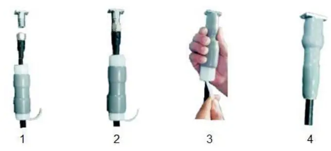
- Insert the cable into the cold shrink tube.
- Tighten the connector.
- Push the cold shrink tube to the top joint, and pull out the strip.
- Ensure the cold shrink tube is tightly fitted with the connection.
For GPS antenna weatherproof, adopt all-weather electrical tape and mastic tape, per the followed figure.
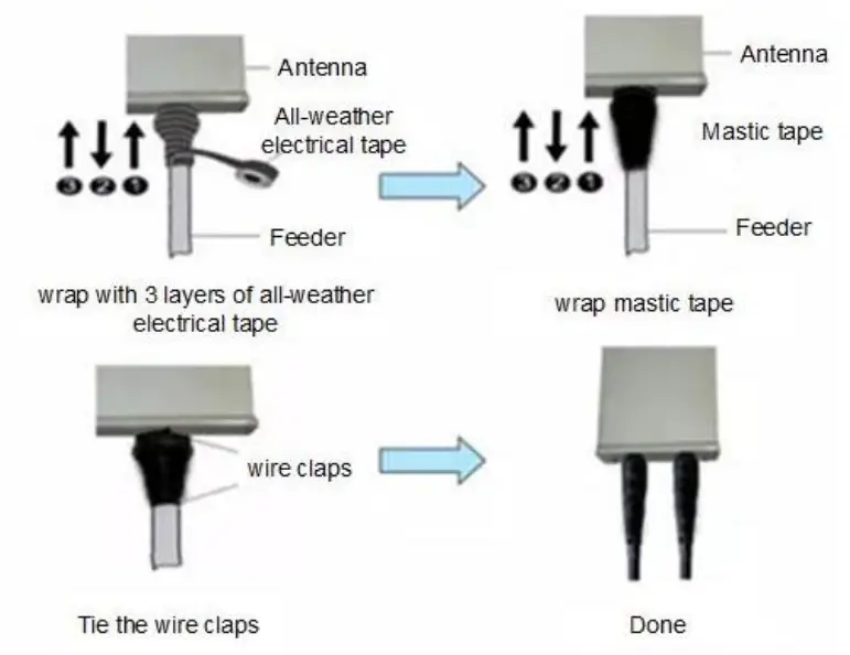
NOTE: Make sure that the wrapping direction of the last layer is from the bottom up. The last layer should be tight enough to keep it from cracking.
Install GPS Antenna
Read the following GPS antenna installation requirements before installing it on the and.
- No major blocking from buildings in the vicinity. Make sure the space atop is at least 45 degrees unblocked by any buildings.
- Avoid installing the GPS antenna in the vicinity of any other transmitting and receiving devices, to avoid interference.
- The GPS antenna should be installed within 45 degrees to the lightning rod.
The GPS antenna system includes an antenna and a connector. The two parts should be assembled according to Figure 2-1.
Figure 2-1 Assemble GPS Antenna
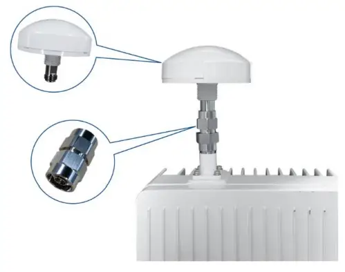
After assembling the GPS antenna, the connector must be waterproofed by all-weather electrical tape and mastic tape.
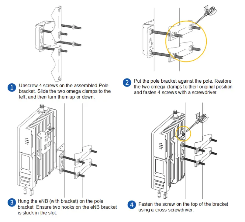
Install on Pole
Check to ensure the diameter of the pole is in the range of 1.6 inches to 2.8 inches (40mm to 70 mm). The position of the eNB on the pole should be at least 47 inches (120 cm) in height.
The brackets have been pre-assembled in manufacturing before packing. It includes two parts, one is pre-assembled on the back of the device. The other is for pole mounting or wall mounting, as shown in Figure 2-2.
Figure 2-2 Pre-assembled Device
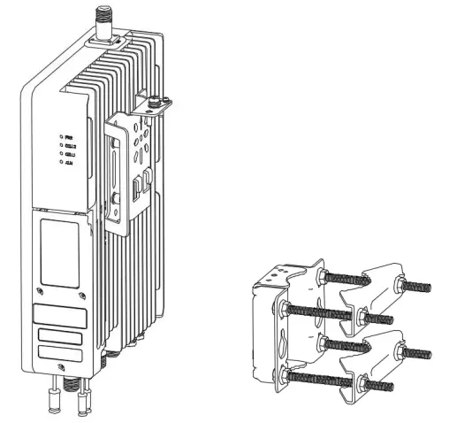
The following will introduce how to fix the pre-assembled eNB on a pole.
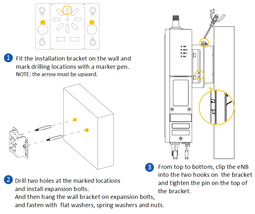
Install on Wall
NOTE: The wall must bear at least 4 times the weight of the eNB.
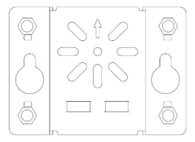
Take apart the assembly bracket first, only remains the wall bracket, as shown in Figure 2-3.
Figure 2-3 Wall Bracket
The following steps introduce how to fix the pre-assembled eNB on a wall.
Connect Cables
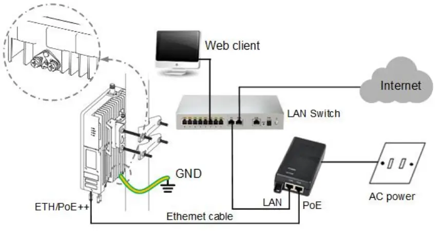
NOTE: The GPS antenna connector and the RF antenna connector must have weatherproof protection, refer to “2.3 Weatherproofing”.
Power On
Power on the end, and wait a few minutes while the B boots up. Per the previous Table 1-1 and Table 1-2 in “1.3 Appearance”, check that the LED indicators are lighting as expected.
P/N: 1701000177
Document version: 01
All rights reserved Baicells Technologies Co., Ltd.


