Baicells Nova-227 Outdoor LTE TDD eNodeB
About
This Document
This document is a guidance of Nova 227 hardware installation for installation personnel , including the preparation of installation tools and supporting materials, the demands for installation environment, installation procedure, cable connection and power on.
Accomplish the installation of the device according to this guide, the installation personnel can avoid potential damage to the device during the installation procedure, which makes sure the subsequent good running of the device. This document suit for the models of pBS2120 and pBS1100x series eNodeBs. Copyright Notice Baicells
copyrights this specification. No part of this specification may be reproduced in any form or means, without the prior written consent of Baicells Disclaimer
This specification is preliminary and is subject to change at any time without notice. Baicells assumes no responsibility for any errors contained herein. For more information, please consult our technical engineers.
Disposal of Electronic and Electrical Waste
Pursuant to the WEEE EU Directive, electronic and electrical waste must not be disposed of with unsorted waste. Please contact your local recycling authority for disposal of this product.
Revision Record
| Date | Version | Description |
| 2 March, 2020 | 01 | Initial Released of new logo. |
Product Overview
Introduction
Baicells Nova 227 is high performance outdoor micro eNodeB based on TD D LTE technology , which is developed by Baicells . The Nova 227 supports wired backhaul
connect ions to backbone network s , and provides LTE access to user terminals, implemented voice and data service transmission s
The Nova 227 make s use of the current transmission resources to re duce the operator’s investment , implement the low cost construction of LTE network s and enhance indoor cover age , thereby providing high speed b road band access for users in assembly occupations. The Nova 227 can be widely used by telecom operators, broadban d operators, and enterprises, etc.
Features
- Adopt the integration design of baseband and RF , flexible to deploy
- Based on 3GPP international standard LTE TDD technology; provide high speed data service; support a maximum transfer rate of DL: 110Mbit/s, UL: 14 Mbit/s with 20MHz spectrum.
- Support flexible uplink and downlink time slot ratio: 0(3:1), 1(2:2), 2(1:3), and high speed data transmission.
- Support 5 MHz/ 1 0MHz/ 1 5 MHz/ 20MHz operation bandwidth.
- Support internal antenna and GPS.
- Support PoE+ power supply, only one Ethernet cable realize data transmission and power supply.
- Security services to provide timely protection against potential security risks and illegal intrusion.
- Support simple and convenient local and remote web management.
- Integration as required, easy to installation and deployment, accurate cover age and improve d network capacity
- Support network management function s, which include s the management, monitoring and maintenance.
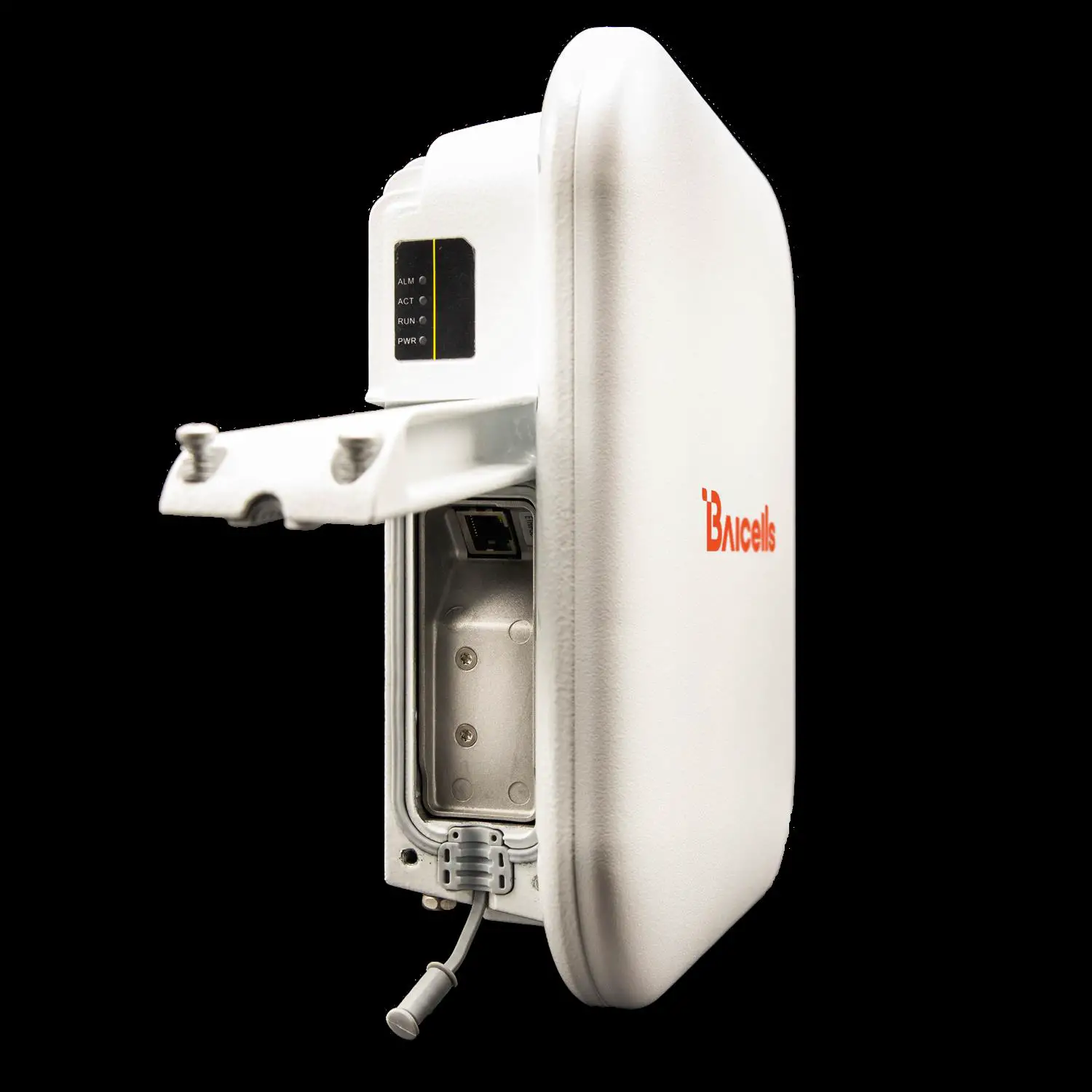
Appearance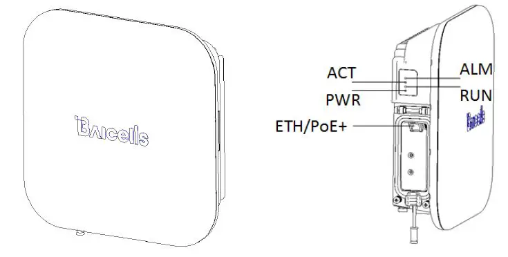
Table1-1 Nova 227 Interface Description
| Interface Name | Description |
| ETH/PoE+ | RJ-45 interface, used for data configuration or data backhaul, and PoE+ power supply. |
Table 1-2 Nova 227 Interface Indicators
| Identity | Color | Status | Description |
| PWR | Green | Steady On | Power On |
| OFF | No Power Supply | ||
| ACT | Green | Steady On | The cell is activated. |
| OFF | The cell is not activated. | ||
|
RUN |
Green | Fast flash: 0.125s on,0.125s off | The board is loading. |
| Slow flash: 1s on,1s off | The board is normal. | ||
| OFF | No power input or board fault | ||
| ALM | Red | Steady On | Hardware alarm, e.g. VSWR alarm |
| OFF | No alarm |
Technical Specification
Hardware Specification
| Item | Description |
| LTE Mode | LTE TDD |
| LTE Bands | Band38/39/40/41/42/43/48 |
| Channel Bandwidth* | 5/10/15/20 MHz |
| Output Power | 24±2dBm/Ant |
| Receive Sensitivity | -100 dBm @band42/43/48 -101 dBm @band38/39/40/41 |
| Synchronization | GPS |
| Backhaul | 1 x RJ-45 Ethernet interface (1 GE) |
| MIMO | DL: 2 x 2 |
| Dimension | 248mm (H) x 248mm (W) x 80mm (D) |
| Installation Type | Pole, wall |
| Antenna | 14.5dBi, internal high gain antenna Horizontal beam width 65°, vertical beam width 20° Polarization mode: ±45° |
| Overall Power | < 20 W |
| Power Supply | PoE+, IEEE802.3at standard |
| Weight | About 2.0 kg |
* The model pBS2120 only support 10MHz/20MHz.
Note: The test method of r eceiving sensitivity is proposed by the 3GPP TS 36.104 , which is based on 5MHz bandwidth, FRC A1 3 in Annex A.1 QPSK R=1/3 25RB standard.
Software Specification
| Item | Description |
| LTE Standard | 3GPP Release 9 |
|
Peak Rate | Ÿ 20 MHz: SA0: DL 50 Mbps, UL 42 Mbps SA1: DL 80 Mbps, UL 28 Mbps SA2: DL 110 Mbps, UL 14 Mbps Ÿ 10MHz: SA0: DL 25 Mbps, UL 21 Mbps SA1: DL 40 Mbps, UL 14 Mbps SA2: DL 55 Mbps, UL 7 Mbps |
| User Capacity | 96 concurrent users |
| QoS Control | 3GPP standard QCI |
| Item | Description | ||
| Modulation | UL: QPSK, 16QAM, 64QAM DL: QPSK, 16QAM, 64QAM | ||
| Voice Solution | CSFB, VoLTE, eSRVCC | ||
| Traffic Offload | LIPA (Local IP Access) SIPTO (Selected IP Traffic Offload) | ||
| SON | Automatic setup ANR (Automatic Neighbor Relation) PCI confliction detection | ||
| Spectrum Scanning | Supported | ||
| UL Interference Detection | Supported | ||
| RAN Sharing | Supported | ||
| Network Management Interface | Support TR069 interface protocol | ||
| MTBF | ≥ 150000 hours | ||
| MTTR | ≤ 1 hour | ||
|
Maintenance | Support remote/local maintenance, based on SSH protocol | ||
| Support remote maintenance | |||
| Support online status management | |||
| Support performance statistics | |||
| Support failure management | |||
| Support configuration management | |||
| Support local or remote software upgrading and loading | |||
| Support log | |||
| Support connectivity diagnosis | |||
| Support automatic start and configuration | |||
| Support alarm reporting | |||
| Support KPI Recording | |||
| Support user information tracing | |||
| Support signaling trace |
Environment Specification
| Item | Description |
| Operating Temperature | -40°C to 55°C |
| Storage Temperature | -45°C to 70°C |
| Humidity | 5% to 95% |
| Atmospheric Pressure | 70kPa to 106kPa |
| IP Protection Grade | IP66 |
Installation Guide
Installation Preparation
Supporting Materials
| Item | Description |
| Ethernet cable | Outdoor CAT6, Shorter than 100m (330 ft) |
| Ground cable | 16mm² yellow-green wire |
Installation Environment
Locational Requirements
Environments with high temperatures , harmful gases, unstable voltages, volatile vibrations, loud noises, flames , explosives and electromagnetic interference (large radar
stations , transmitting stations , transformer substations ) are not suitable for the operation of Nova 22 7 , and thus should be avoided. Places prone to have impounded water, soaking, leakage, or condensation, should also be avoided.
Factors like climate, hydrology, geology, earthquake, electric power, and transportation should be taken into consideration in the construction process so that a proper location can be chosen to meet the communication engineering environmental requirements, as well as the technical requirements of network planning and communication equipment.
Environmental Requirements
| Item | Range |
| Operating Temperature | -40°C to 55°C |
| Relative humidity (no condensation) | 5% to 95% |
Personnel Requirements
The installation personnel must master the basic safe operation knowledge, through the training, and having the corresponding qualifications.
Install on Pole 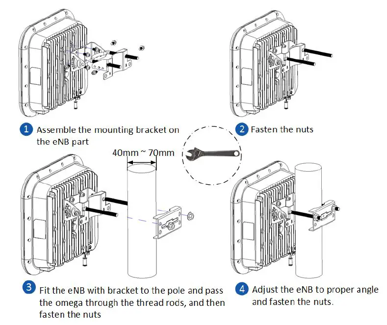
Install on Wall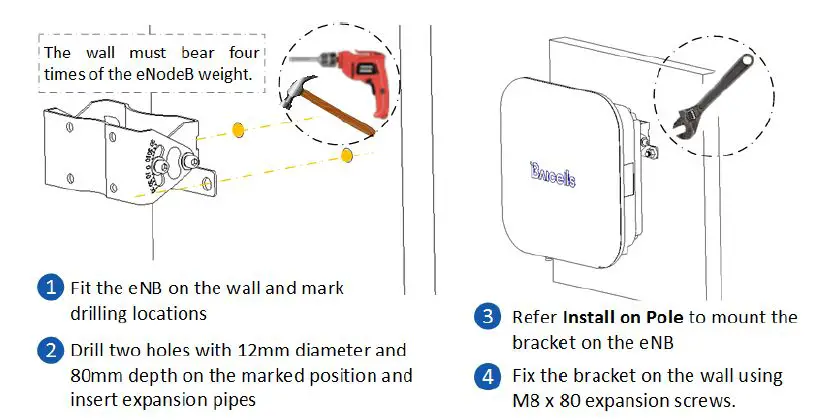
Connect Cable
Before connect cables, unscrew the three screws on the cover of wiring cavity using M4 cross screwdriver and open the wiring cavity. After complete the connection, close the cover and fasten screws.
Note: If the base station need to debug, connect the LAN interface to PC first and configure the IP address of the PC with 192.168.150.x.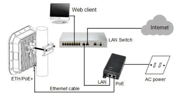
Connect Ground Cable
CAUTION: It is unlikely to happen but since the LTE eNode B is a kind of very sophisticated equipment, so it is recommended to test it on the ground to make sure everything is functioning before install on the tower.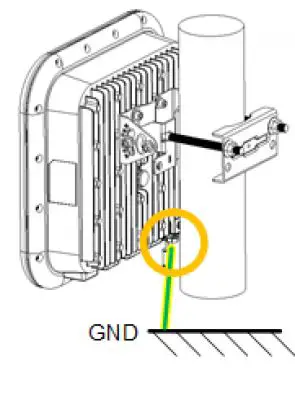
Power ON:
After
the Nove 227 is powered on, indicators can hint the status of the eNodeB.
Only apply to the model pBS2120.
FCC Compliance
This device complies with part 15 of the FCC Rules. Operation is subject to the following two conditions: (1) This device may not cause harmful interference, and (2) this device must accept any interference received, including interference that may cause undesired operation. Any Changes or modifications not expressly approved by the party responsible for compliance could void the user’s authority to operate the equipment. This equipment has been tested and found to comply with the limits for a Class B digital device, pursuant to part 15 of the FCC Rules. These limits are designed to provide reasonable protection against harmful interference in a residential installation. This equipment generates uses and can radiate radio frequency energy and, if not installed and used in accordance with the instructions, may cause harmfu l interference to radio communications. However, there is no guarantee that interference will not occur in a particular installation. If this equipment does cause harmful interference to radio or television reception, which can be determined by turning the equipment off and on, the user is encouraged to try to correct the interference by one or more of the following
measures:
- Reorient or relocate the receiving antenna.
- Increase the separation between the equipment and receiver.
- Connect the equipment into an outlet on a circuit different from that to which the receiver is connected.
- Consult the dealer or an experienced radio/TV technician for help.
Warning: This equipment complies with FCC radiation exposure limits set forth for an uncontrolled environment. This equipment should be installed and operated with minimum distance 3 0cm between the radiator & your body.![]()


