![]()
BS422 installation and setup
guideline
Ver. 1.30
The information contained in this document is the property of Damm Cellular Systems A/S. This document is subject to copyright and shall not be published or reproduced, in whole or in part, without the written permission of Damm Cellular Systems A/S.
© 2010 Damm Cellular Systems A/S. All rights reserved. Møllegade 68, DK-6400 Sønderborg, Denmark
Phone: +45 74 42 35 00, Fax: +45 74 42 30 31,
E-Mail: [email protected],
http://www.damm.dk
INTRODUCTION
This manual is intended for installation and configuration of the BS422 for operational use.
It is recommended that engineers doing the installation and configuration of a BS422 have practical experience in installation of radio and computer systems, and have made themselves familiar with the BS422 equipment through appropriate DAMM training courses and study of the content of the TetraFlex manual and other documentation from DAMM.
IMPORTANT:
Updates/changes / important information related to the TetraFlex® system and software may be downloaded from the protected part of www.damm.dk
Please check this URL for updated information before attempting to install or correct errors
NOTE: Chapters marked with a ![]() indicate areas where special care must be taken to avoid personal injury or damage to the equipment.
indicate areas where special care must be taken to avoid personal injury or damage to the equipment.
![]() Before starting installation and configuration, please read the entire manual carefully.
Before starting installation and configuration, please read the entire manual carefully.![]() NOTE: It is the responsibility of the system owner/operator to ensure that only authorized service persons has access to the inside circuits of the BS422
NOTE: It is the responsibility of the system owner/operator to ensure that only authorized service persons has access to the inside circuits of the BS422![]() NOTE: It is the responsibility of the system owner/operator to ensure that all local legislation, rules, and regulations are complied.
NOTE: It is the responsibility of the system owner/operator to ensure that all local legislation, rules, and regulations are complied.![]() Internal fuses protect the BS422. Always replace with fuses of equivalent value and type.
Internal fuses protect the BS422. Always replace with fuses of equivalent value and type.
General Warning
This manual contains important safety and operational information. Please read and follow the instructions in this manual. Failure to do so could be hazardous and result in damage to your device.
Changes and modifications to this device not expressly proved by DAMM could void the user’s authorization to operate this device
North America regulations
The Base Station Transceivers and products devices mentioned in this User Manual comply to FCC part 90 and Industry Canada (IC) RS119 regulations for such equipment. The equipment has been tested and found to comply with the limits for a Class A digital device, pursuant to part 15 of the FCC Rules. These limits are designed to provide reasonable protection against harmful interference when the equipment is operated in a commercial environment. The equipment generates, uses, and can radiate radio frequency energy and, if not installed and used in accordance with the instruction manual, may cause interference to radio communications.
Canadian regulations
Under Industry Canada regulations, this radio transmitter may only operate using an antenna of a type and maximum (or lesser) gain approved for the transmitter by Industry Canada. To reduce potential radio interference to other users, the antenna type and its gain should be so chosen that the equivalent isotropically radiated power (e.i.r.p.) is not more than that necessary for successful communication.
RF Exposure
The DAMM-developed transmitting devices mentioned in this User Manual have the Nemko approval concerning “Maximum Permissible Exposure Calculations” which are the European limits for maximum permissible exposure defined in the document 1999/519/EC, Council Recommendation of 12. July 1999. A summary of the results is listed below. The specific Nemko Document 128948/5 and 365007-07r01 can be obtained by request from the DAMM Support Department.
In the USA RF Exposure compliance is determined at time of licensing.
In Canada the following minimum safety distances should be maintained based on maximum authorized output power.
RF Exposure Requirements(Canada):
| Tx.Freq. band: 68-174 MHz | ||
| TR type | Power | Safety Distance m/ft |
| BS422 68 MHz | 450 W E.I.R.P. | 5-5-18 |
| 273 W E.R.P. | 5-5-18 | |
| BS422 146 MHz | 794 W E.I.R.P. | 7.5/24.6 |
| 484 W E.R.P. | 7.5/24.6 | |
| Tx.Freq. band: 410-470 MHz | ||
| TR type | Power | Safety Distance m/ft |
| BS422 420-470 MHz | 794 W E.I.R.P. | 6.5/21.3 |
| 484 W E.R.P. | 6.5/21.3 | |
| Tx.Freq. band: 851-869 MHz | ||
| TR type | Power | Safety Distance m/ft |
| BS422 851-869 MHz | 603 W E.I.R.P. | 6.5/21.3 |
| 368 W E.R.P. | 6.5/21.3 | |
Additionally, a summary of the FCC RF Exposure Requirements is shown in the list below.
RF Exposure Requirements:
| Tx.Freq. band: 68-174 MHz Antenna gain: 12 dBi Cable loss: 0dB | ||
| TR type | Power | Safety Distance cm/ft |
| BS422 68 MHz | 1 carrier 50 W DMR | 650/22.3 |
| 1 carrier 50 W Analog | 650/22.3 | |
| BS422 146 MHz | 1 carrier 25 W TETRA | 650/22.3 |
| 1 carrier 10 W TEDS | 650/22.3 | |
| Tx.Freq. band: 410-470 MHz Antenna gain: 5.2 dBi Cable loss: | ||
| TR type | Power | Safety Distance cm/ft |
| BS422 410 MHz | 1 carrier 50 W Analog | 300/9.8 |
| 1 carrier 25 W TETRA | 200/6.6 | |
| 2 carrier 10+10 W TETRA | 150/4.9 | |
| 3 carrier 3×4.4 W TETRA | 150/4.9 | |
| 4 carrier 4×2.5 W TETRA | 120/3.9 | |
| Tx.Freq. band: 851-869 MHz Antenna gain: 10 dBi Cable loss: | ||
| TR type | Power | Safety Distance m/ft |
| BS 422 . 851.1 MHz | 60.26 W | 6.5/21.3 |
| BS 422 , 860.0 MHz | 60.26 W | 6.5/21.3 |
| BS 422 , 868.8 MHz | 60.26 W | 6.5/21.3 |
Antennas
The outside antenna connected to this device must be installed on an outdoor permanent structure.
Keep a separation of at least 6 meters / 20 feet from all persons during normal operation.
Notice
❖ Do not modify any part of this device for any reason
❖ Do not place any combustible material near the transceiver
❖ Do not spray any liquid over the device
❖ Ensure that the power and antenna connections are securely made, using cables recommended and with excess capacity for the power being utilized.
Installing more BS422 according to user manual and using DAMM filter and combiner systems together with tested and verified cabling, connectors, and antennas – will avoid any problems with intermodulation. Installation of the maximum number of transceivers will not extend the maximum range of calculated output power and intermodulation according to the DAMM products sheets. Any BS type determines how many TR modules can be installed and the whole BS design has taken the Tetra specification on the subject matters into consideration. This is e.g. reflected in all DAMM EU certificates/grants and test reports of which you can find on our web page.
Please notice that any BS type/mode shipped to end customer is fully assembled and tested from factory. No assembly is needed in the field except setting up the BS rack or mount the outdoor unit putting on power and LAN/WAN connections.
The installation and user manual refer to product sheets for any unit in the rack which can be accessed on our web page / restricted area for customers and any customer/partner can request a paper copy hereof.
Installing DAMM BS422 according to this installation manual – will prevent issues with RF exposure according to our certifications (see web page).
DAMM User Manual describes installation practices and contains section with recommended BS hardware. Recommended external hardware, cables etc. is tested and verified with DAMM BS-equipment.
REVISION
Software covered by this manual (for information about other TetraFlex software modules see TetraFlex 8.xx user manual):
Covered TetraFlex 8.xx modules
| Software module | Version |
| Node.exe | 8.1 |
| OM.exe | 8.01 |
| TR.exe | 8.01 |
Record of Manual Versions Numbers
| SW. | Ver. | Release Date | Main Cause of change | Author | Approved |
| 8. | 1.00 | 15-11-2019 | Initial release | JR | |
| 8.10 | 1.00 | 30-08-2021 | Yearly update, std. release | JR | |
Record of Changes of Documents since last Manual Version Number
| Man. ver. | Sec. | Page | Cause of change | Date | Initial |
| 1.20 | 4 | RF Exposure Requirements, 800 MHz added | 14-12-2021 | ASL | |
| 1.30 | 4 | RF Exposure Requirements, 800 MHz added | 9-3-2022 | ASL | |
IMPORTANT:
DAMM will execute great effort to maintain and update this manual so it will always be up to date regarding information and readability.
To do this DAMM needs to get feedback from you. So, if you as reader find anything that could be done better, items that is not dealt with, sections that is difficult understandable etc. DAMM would appreciate your comments Please mail support on [email protected] or Contact support on +45 73473520
Thank you for your input.
ABBREVIATIONS / DEFINITIONS
| Short | Explanation / Definition |
| AIE | Air interface encryption |
| API | Application Programming Interface |
| Application Date | Is checked against the Dongle Application Date Limit. Software package execution is only possible if Application Date is equal or less than the Dongle Application Date Limit. The Application Date is hard coded into the software package and will normally be the same date as the Release Date, but can be set to an earlier date. |
| Application Date Limit. | All software packages with an Application Date earlier than this Application Date Limit can be executed |
| Application PC | Any PC. with the exception of RF nodes, which are running DAMM application(s) |
| BS | Base Station. BS41x or a combination of SE3421’s and BS421’s |
| BSC | Base Station Controller |
| BSC.exe | Base Station Controller Software |
| BSS | Base Station Switch |
| CAD | Call Authorized by Dispatcher |
| CDR | Call Data Records |
| Cell | (Radio) Cell — a radio node with one or more transceivers |
| Cell ID | ID is broadcasted every 10 sec (configurable). |
| CF | Compact Flash memory card |
| CMoIP | Circuit Mode over IP |
| DB | Data Base |
| DCK | Derived Cipher Key |
| DGNA | Dynamic Group Number Assignment |
| Dongle | A USB dongle, programmed by DAMM. to be inserted in the node and/or application PC. The dongle controls which functions and applications can be executed |
| Dongle Date Limit | When this date is exceeded the dongle will not allow execution of DAMM software packages |
| DSA | Dynamic Subscriber Assignment |
| DSP | Digital Speech Processing |
| E2E | End to end encryption |
| ETSI | European Telecommunications Standard Institute |
| FACCH | Fast Associated Control Channel |
| FTP | File Transfer Protocol |
| GCK | Group Cipher Key |
| GIS | Geographical Information system |
| GPS | Global Positioning System |
| GSI | Group Subscriber Identity |
| GUI | Graphical User Interface |
| GW | Gate Way |
| IP | Internet Protocol |
| ITSI | Individual Tetra Subscriber Identity |
| L1 Warning | System function is not likely to be affected |
| L2 Alarm | System function is partly affected |
| L3 Blocked | Some components of the system are not active |
| LAN | Local Area Network (For TetraFlexe meaning connection BSC/TR and IP backbone) |
| MCC | Mobile Country Code |
| MCCH | Main Control Channel |
| Missing | A node which has been visible is missing |
| NM | Network Management |
| MNC | Mobile Network Code |
| MS | Mobile Station (Terminal) |
| Node | Any unit, with exception of redundant BSC(s). running the DAMM bsc.exe application |
| OM | See TetraOM |
| OS | Operation System. Windows XP. Vista. 7. CE etc. |
| PABX | Private Automatic Branch Exchange |
| PC | Normally the BSC, but could also refer to a standard consumer PC |
| PD | Packet Data |
| PEI | Peripheral Equipment Interface |
| PSTN | Public Switched Telephone Network |
| PTT | Push to Talk |
| RAM | Random Access Memory |
| Release Date. | The date where DAMM releases the software. This date is hard coded into the software package |
| Release number | Hard coded into the software package and have 2 levels, separated with a dot (example: 7.40) |
| SACCH | Slow Associated Control Channel |
| SCCH | Secondary Control Channel |
| SCK | Static Cipher Key |
| SDS | Short Data Service |
| SELV | Safety Extra Low Voltage |
| Site | Geographical position of equipment or nodes |
| SLA | Service Level Agreement, earlier called ‘Service and Maintenance Agreement” (SMA). |
| SNMP | Simple Network Management Protocol |
| Software package | A package containing all functions and applications available on the release date. |
| SSI | Short Subscriber Identity |
| Subscriber register | Register where the variable data regarding subscribers and profiles are stored. |
| TBD | To Be Determined |
| TCP | Transmission Control Protocol |
| TEAL… | Tetra Encryption Algorithm t… 2…. 3… 4… etc. |
| TEI | Tetra Equipment Identification |
| TETRA | Terrestrial Trunked Radio |
| TetraOM | The DAMM Tetra Operations & Management command line application |
| ToIP | Tetra over IP |
| TSI | Tetra Subscriber Identity. consist of MCC:MNC: SSI |
| UDP | User Datagram Protocol |
| User number | Unique DAMM subscriber reference used as an example by the voice GW and to manage terminal exchange |
| UTP | Unshielded Twisted Pair |
| VoIP | Voice over IP |
| WAN | Wide Area Network (For TetraFlexE meaning connection to www.gateways.etc.) |
OPERATIONAL DESCRIPTION OF THE BS422
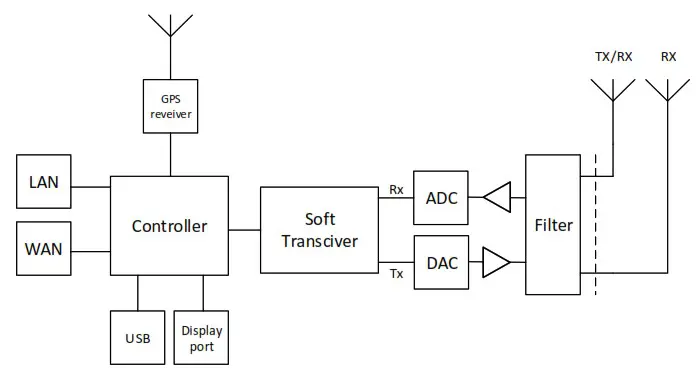
The BS422 has all the RF circuitry required for a completely self-contained base station. Its main RF components are outlined in Chapter “BS422 main components”.
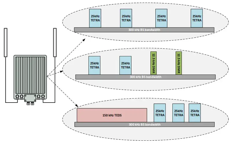
The BS422 is a multi-technology basestation that is based on a Software Defined Radio, which enables it to operate several different radio technologies:
- TETRA
- TEDS
- DMR Tier 3
- Analog PMR
Each BS422 can operate up to four different carriers simultaneously, independent of the selected radio technology, inside a defined band.
The different carriers may operate in different bandwidths depending of the selected technology.
Hardware
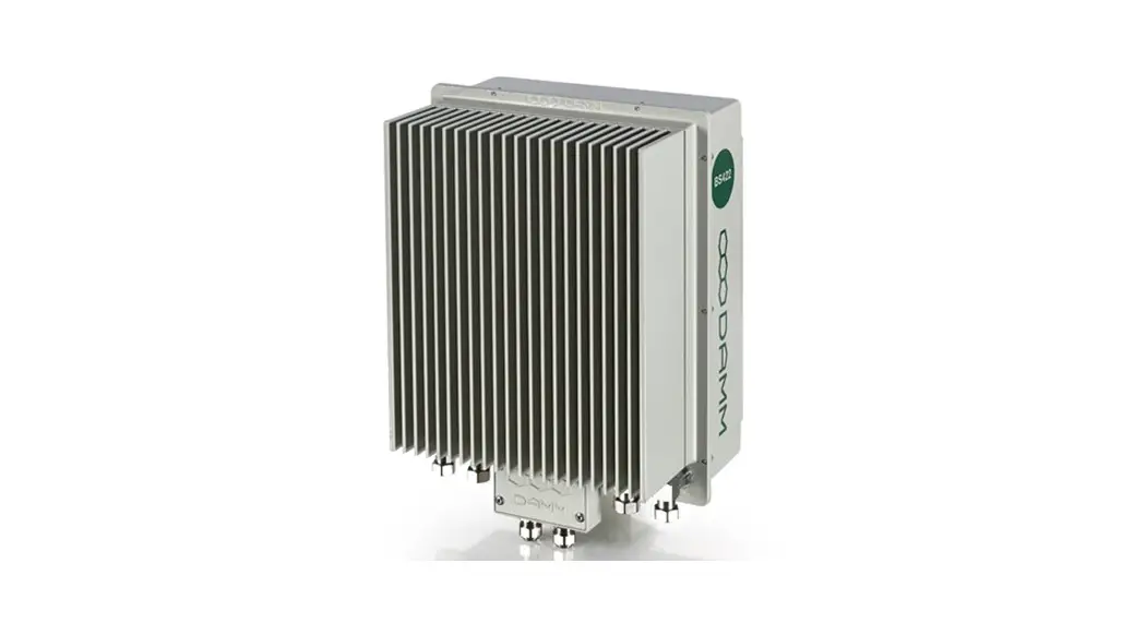
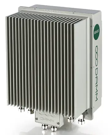
The BS422 is a compact single-box unit with build in duplex filter.
The concept is based on a decentral architecture, which means that no further components like servers or switches are needed. All features for a functional trunked radio system is build into the BS422. The basestation is designed for direct outdoor mounting.
Block diagram:
Dimensions:
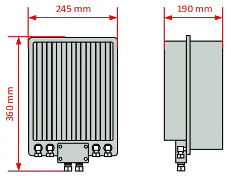
| Weight | 9 Kg (approximately) |
| Power supply | External -48Vdc source, 100 W (approximately @ full output power) |
| Cooling | Natural convection (vertical or horizontal cooling plates avaliable) |
| RF connectors | N-type, female |
| Control/LAN/WAN | 100 Mbps Ethernet, LSA connector |
| Network Management | MS Windows Remote Desktop |
BS422- INSTALLATION
Environmental / climatic requirements
The Base Station is designed for outdoor operation, such that it can be placed in the antenna mast close to the antennas.
The Base Station is designed to be able to operate at severe environmental conditions.
The Base Station is guaranteed to operate under ambient air temperatures from –25°C to +55°C Celsius. Maximum BS422 cabinet temperature is +85°C. Storage temperature for the BS422 is from –40°C to +85°C.
Note that the guaranteed MTBF data is valid only within the standard specified temperature range Screening of BS422 to specific customer-defined temperature range (from -40°C to +55°C ambient air temperature) is optional upon request.
The Base Station encapsulation complies with IP65
Placement
The recommended placement of the Base Station is as close to the antennas as possible to reduce cable loss. The placement of the Base Station shall be such that it is securely fastened to a mast or building that is able to carry the weight of the BS422 and withstand the local environmental conditions. All cables, antennas etc. shall be properly fastened to the mast or building using appropriate fixtures as to avoid damage to the equipment and possible injury to persons.
Grounding
The BS requires careful grounding.
Grounding is important to protect the equipment when inserting/removing cables and to protect the operator from faulty equipment.
An effective grounding is also important to protect the installation during thunderstorm (lightning).
The grounding shall be as specified in paragraph “1.2.6 Power connection to SB422”
BS422 main components
Filter cover and filters removed. BS viewed from the filter (back) side
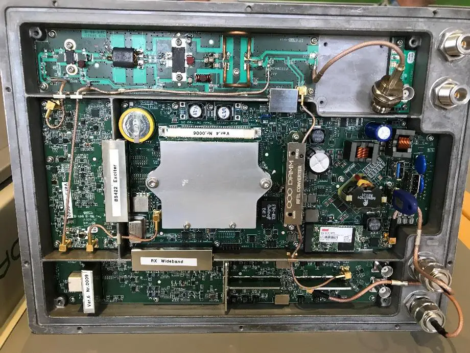
Figure 1-1: BS422 main components
The HDMI monitor connector together with the USB connector allows a connection of a standard monitor and mouse/keyboard connection
If monitor, keyboard, and mouse are connected, the Windows 10 operation system in the BS422 can be accessed directly for configuration or faultfinding purposes
To access the connectors, remove the filter cover To access the CF card also remove the filter mounting plate The connectors need not to be unscrewed, just carefully lift the filter base plate slightly and the CF card can be removed/inserted
Attaching RX/TX antennas
Before installing the Base Station please read the application note in the TetraFlex user manual about the Antenna Systems.
The following antenna cables shall be attached:
Single BS422 installation recommendation
o 3 cables to the BS422 (one for Tx/Rx-A, one for Rx-B, and one for GPS*)
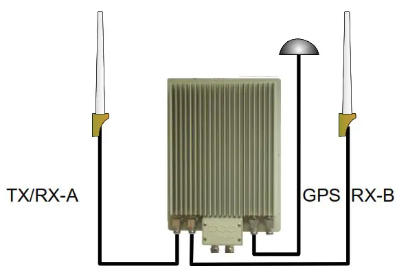
Figure 1-2: Single BS422
NOTE: The BS422 will function with only Tx/Rx-A and without GPS antenna with the following limitations:
Timing via GPS will not be available (BS422 runs on internal oscillator – Not recommended) and there will be no Diversity when only using one Rx antenna.
Dual BS422 installation recommendation
o Cables to the 2 x BS422 (two for TX/RX, two for GPS* and two for RX-B / A-OUT between the BS422’s)
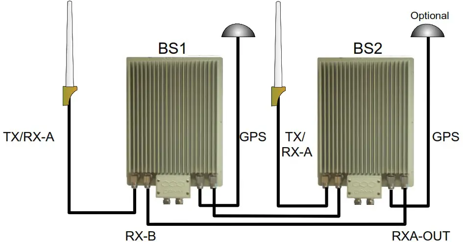
Figure 1-3: Dual BS422
NOTE: 2 x BS422 with 2 GPS antennas will provide full GPS redundancy (Antenna and GPS receiver) *If using BS422 with build in GPS Antenna the external is not connected.
Power connection to BS422
![]() Before starting this task, please read the entire chapter carefully.
Before starting this task, please read the entire chapter carefully.
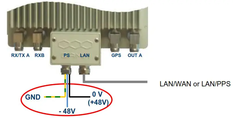
Figure 1-4: Power connection
The BS422 is operated at -48V nominal DC SELV (Safety Extra Low Voltage).
![]() DO NOT UNDER ANY CIRCUMSTANCES USE A POWER SUPPLY THAT HAS THE MINUS CONNECTED TO POWER SUPPLY CHASSIS
DO NOT UNDER ANY CIRCUMSTANCES USE A POWER SUPPLY THAT HAS THE MINUS CONNECTED TO POWER SUPPLY CHASSIS
![]() The cables used for power supply must be equal to or more than 3 x 1,5mm 2
The cables used for power supply must be equal to or more than 3 x 1,5mm 2
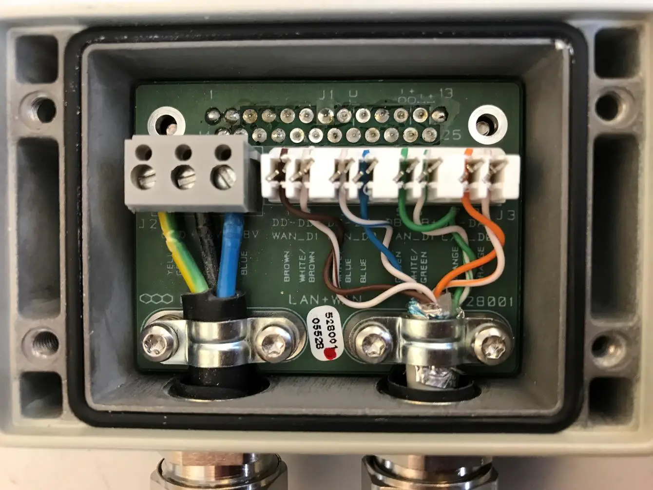
Connect the three wires in the power connection cable according to the color markings inside the BS422 system connector.
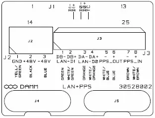
System Connector
There is two type of System Connetors:
- System Connector with LAN and WAN (30528001)
- System Connector with LAN and PPS (30528002)
Use a LSA tool for the Ethernet connection, a small flat screwdriver for the power connector, and torx screwdriver for the fastner clamps.

Figure 1-5: System Connector
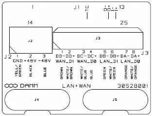
Cable connection for LAN, WAN- 30528001:
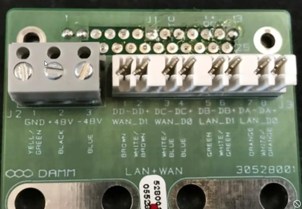
NOTE: Cable used must be 0.4mm 2 to 0.6mm 2 (24AWG) solid cores
LAN /WAN connector:
Ethernet Connection
The BS422 supports either 2 x 100 Mb/s. Ethernet connection for WAN and LAN or as an option 1 x 100Mb/s Ethernet for LAN and a Ethernet type DC connection for timing (PPS).
The purpose of the connections is
- To establish connection for control of the base station
- To establish connection to other BS422 and for timing and synchronization. (1 sec Pulse- PPS).
The Ethernet connections are limited to SELV (Safety Extra Low Voltage) connections.
The PPS DC timing connection can be connected to another BS422 for timing. Arresting units are an integrated part of the BS422 POWER:
NOTE: Cable used must be equal to or more than 3 x 1,5mm 2 (e.g. DAMM no. 883013)
| Ground | GND | 1 | Yellow/Green |
| 0 | + | 2 | Black |
| -48Volt | – | 3 | Blue |
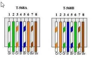
RJ45 Ethernet Connection terminals
RJ45 connection for WAN/ LAN:
| LAN CABLE CAT.5/6 | |||||
| RJ45 | DAMM COLOR | TSBBA COLOR | TSBEM COLOR | FUNCTION | |
| SH | SHIELD | SHIELD | SHIELD | SHIELD | |
| 8 | BROWN | BROWN | BROWN | DD- | WAN_DI |
| 7 | WHITE | WHITE/BROWN | WHITE/BROWN | DD+ | WAN_DI |
| 5 | WHITE | WHITE/BLUE | WHITE/BLUE | DC- | WAN_ D0 |
| 4 | BLUE | BLUE | BLUE | DC+ | WAN_De |
| 6 | ORANGE | ORANGE | GREEN | DB- | LAN_DI |
| 3 | WHITE | WHITE/ORANGE | WHITE/GREEN | DISH | LAN_DI |
| 2 | GREEN | GREEN | ORANGE | DA- | LAN_DO |
| 1 | WHITE | WHITE/GREEN | WHITE/ORANGE | DA+ | LAN-DO |
As shown on Board
Cable connection for LAN, PPS- 30528002:
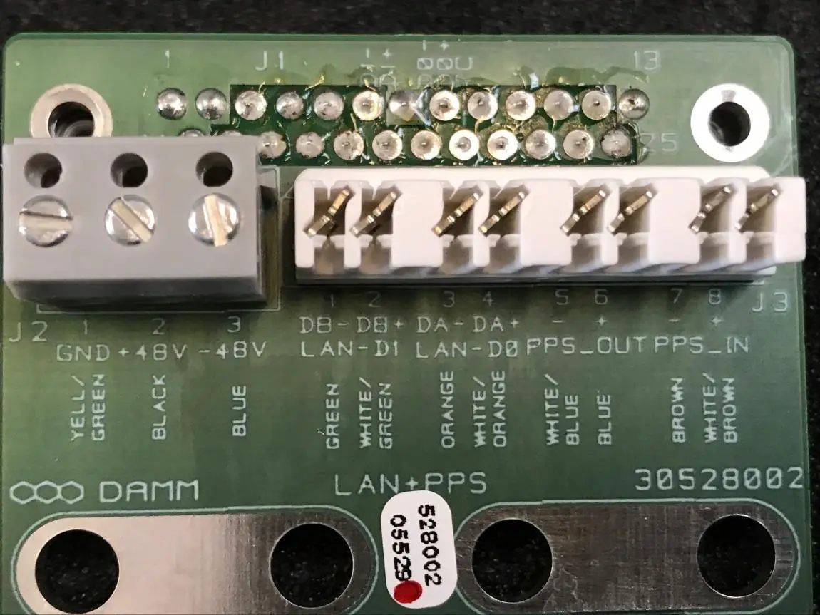
| LAN CABLE CAT.5/5 | |||||
| RJ45 | DAMM COLOR | T55BA COLOR | T5BBEI COLOR | FUNCTION | |
| SR | SHIELD | SHIELD | !A.:=LD | SHIELD | |
| 5 | ORANGE | ORANGE | 3HLEN | DU | LAN_DI |
| 3 | WHITE | WHITE/ORANGE | WHITE/GREEN | DB+ | LAN_DI |
| 2 | GREEN | GREEN | ORANGE | DA- | LAN_ D0 |
| I | WHITE | WHITE/GREEN | WHITE/ORANGE | DA+ | iAN_DO |
| 5 | WHITE | WHITE/BLUE | WHITE/BLUE | DC- | _M _OUT |
| 4 | BLUE | BLUE | BLUE | DC+ | PPS_1N2_OUT |
| 1+. | BROWN | BROWN | BROWN | DP- | F S_MI |
| WHITE | WHITE/BROWN | WHITE/BROWN | DD. | rims_mi | |
As shown on Board
PART-2: Configuration
BS422 CONFIGURATION
The BS422 software is preinstalled from factory with default setting (see bellow) and before the system can be used in an installation this default settings must be adapted to the actual need. Please also consult TetraFlex user manual for more details on how to change settings.
Factory settings:
Login user name: tetraflex (please change for security reasons) Login password: xxxxx (please change for security reasons)
LAN IP: 172.16.1.10
WAN IP: auto (DHCP)
Node No.: 1 MCC:238
MNC:16024
Mode and TR Physical freq.: Predefined from ordering.
Set-up of LAN and WAN IP address
Open Network and Sharing Center Windows settings:
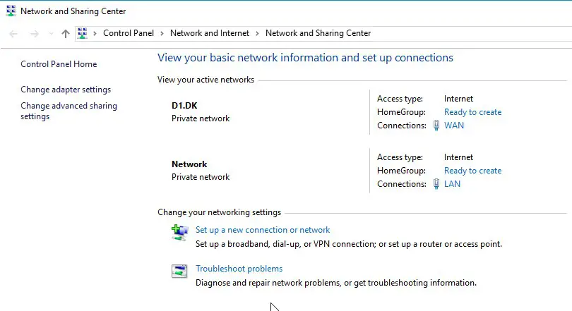
PS: The WAN and LAN connections will only showup if there is an active connection at the other end of the Ethernet cable. If the WAN or LAN connections is not shown you can set the IP address etc. by clicking on the “Change adapter settings” and right click on LAN or WAN and make the setup in “Properities” – “Internet Protocol Version 4”.
Set the WAN and LAN network parameters for you network (see default factory settings)
Setting the frequenzies of the BS422
Some useful TetraOM Commands
For detailed OM overview please see OM help files.
Note Only main commands are listed, subcommands may be available
Node Controller: (Network connection in OM – BSC LAN IP and port 1024)
| S00 | SW Version |
| S00/C | Compiler options |
| S04 | License dongle setting Node |
| S10 | Network status |
| S12 | Tetra Cell Status |
| S13 | Voice GW status |
| S14 | Packet Data Status |
| S15 | Application GW status |
| S16 | Terminal GW status |
| S20 | Subscriber registers |
| S20/SAVE | Save actual register to text file |
| S20/READ | Load data from text file |
| S21 | Subscriber profile |
| S22 | SSI Register Status |
| R/S65 | (repeating) Multicast / Unicast addresses |
| S71 | General Node configuration |
| R/S99/TS | (repeating) Shows all timeslots |
TR422 Transceiver:
(Network connection in OM – BSC LAN IP and port 42022)
| 0 | SW Version |
| 1 | Display TR Status |
| 03/A | Alarm Flags* |
| 5 | BSC status |
| 6 | Input Power |
| 10 | TX key state |
| 11 | TX output |
| 21 | RSSI level |
| 31 | OCXO sync |
| R/34 | (repeating) Display all CMoIP connections |
| R/63 | (repeating) Internal GPS status |
| 63/VER | GPS module version |
| 71 | Common system configuration |
| 71/TXREFLWR/c | SWR alarm setting (- Tx reflected blocking alarm (default, + warning only alarm) |
| 98 | Hardware ID |
| 99/RESTART | Restart BS421 (Soft restart) |
| ‘) Alarm BS 422 (OM command OVA) | Comment |
| 00: TX PLL unlocked | Blocking Alarm (Hardware fault) |
| 01: TX loop unstable | Blocking Alarm (Hardware fault) |
| 03: TX temperature high | Blocking Alarm (TR421 temperature over 80’C TX stopped) |
| 6:TX output power | Blocking Alarm (Check TX out power) |
| 7:TX ant. reflected L2 | Blocking Alarm (can be changed to non-blocking with command 71/TXREFLWAR/*) |
| 8:TX ant. reflected LI | Non-Blocking Alarm |
| 10:RX PLL unlocked | Blocking Alarm (Hardware fault) |
| 11:RX LO1 injection low | Non-Blocking Alarm (Hardware fault) |
| 16: 36.864MHz PLL unlocked | Blocking Alarm (Hardware fault) |
| 18:L3 Frequency Setup | Non-Blocking Alarm |
| 19:DSP watchdog | Blocking Alarm |
| 20:DSP Time Sync | Non-Blocking Alarm |
| 21:BSC Message Link | Blocking Alarm (No Link to BSC) |
| 22:BSC 1 Message Link | Non-Blocking Alarm (No Link to BSC1) |
| 23:BSC2 Message Link | Non-Blocking Alarm (No Link to BSC2) |
| 24:Time Sync | Non-Blocking Alarm |
| 25:Internal GNSS RX | Non-Blocking Alarm |
| 26:External 1 Sync input | Non-Blocking Alarm |
| 27:External 2 Sync input | Non-Blocking Alarm |
| 28:Sync Phase Detector | Non-Blocking Alarm |
| 29:Century Second error | Non-Blocking Alarm |
BS422 Installation guide
Specifications subject to change without notice


