Altronix MaxFit11E MaxFit E Series Dual Power Supply Expandable Power Systems
Max Fit E Series Overview:
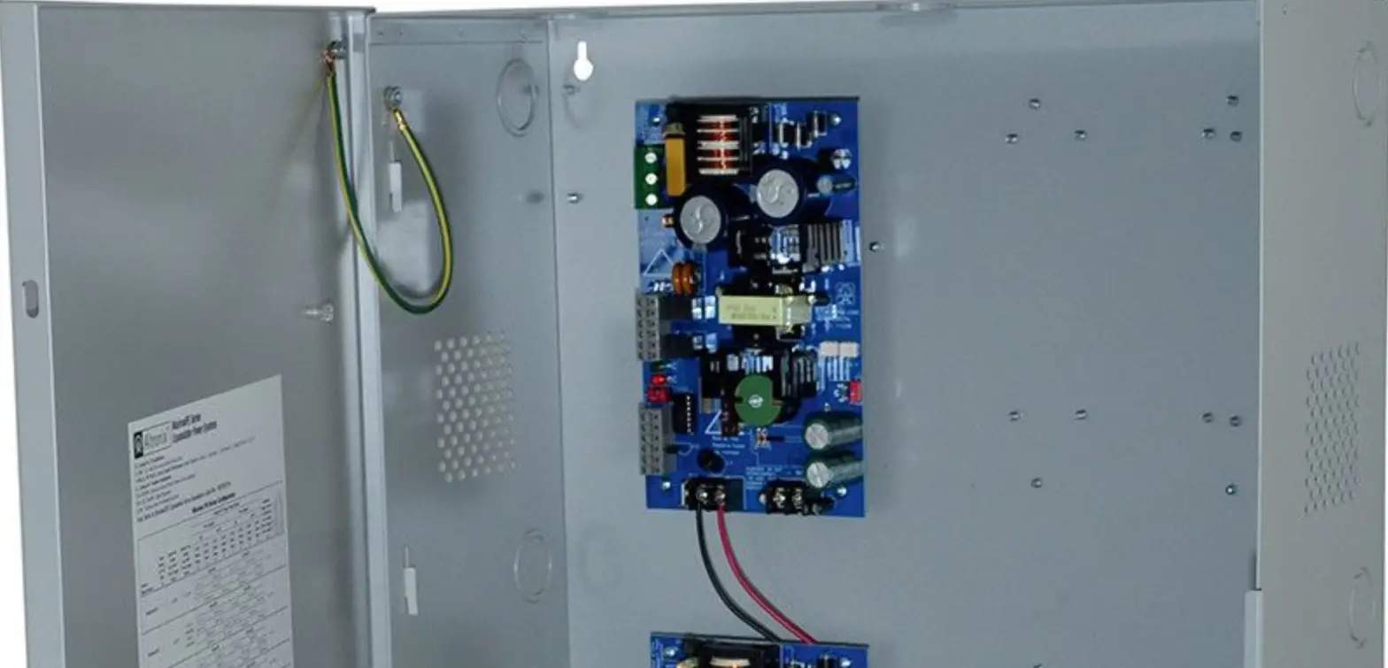
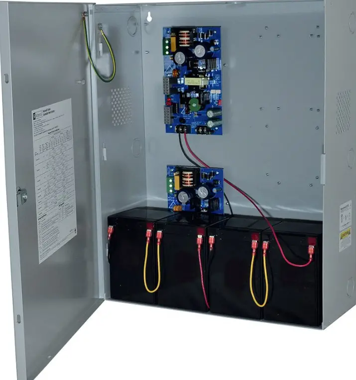
Altronix MaxFit Expandable Power Systems provide system designers and installers with optimum power choices and the highest levels of versatility. They provide 12VDC, 24VDC, or 12VDC and 24VDC simultaneously via two (2) single output power supply/chargers. Suit of features includes AC fail, low battery, and battery presence monitoring. Enclosure accommodates up to four (4) 12VDC/12AH batteries. All interconnecting equipment must be UL Listed.
MaxFit E Series Configuration Chart:
| Altronix Model Number | Output Voltage Options | Non Power- Limited Outputs | Class 2 Rated Power- Limited Outputs | 115VAC 60Hz Input Current | Power Supply Board Input Fuse Rating | Power Supply Board Battery Fuse Rating | |
| Power Supply 1 | Power Supply 2 | ||||||
| MaxFit11E | AL400ULXB2 | AL400ULXB2 | – | 2 | 7.0A | 5A/250V | 15A/32V |
| 12VDC @ 4A | 12VDC @ 4A | ||||||
| 12VDC @ 4A | 24VDC @ 3A | ||||||
| 24VDC @ 3A | 24VDC | ||||||
| MaxFit13E | AL600ULXB | AL400ULXB2 | 1 | 1 | 7.0A | 5A/250V | 15A/32V |
| 12VDC @ 6A | 12VDC @ 4A | ||||||
| 24VDC @ 6A | 12VDC @ 4A | ||||||
| 12VDC @ 6A | 24VDC @ 3A | ||||||
| 24VDC @ 6A | 24VDC @ 3A | ||||||
| MaxFit33E | AL600ULXB | AL600ULXB | 2 | – | 7.0A | 5A/250V | – |
| 12VDC @ 6A | 12VDC @ 6A | ||||||
| 12VDC @ 6A | 24VDC @ 6A | ||||||
| 24VDC @ 6A | 24VDC @ 6A | ||||||
| MaxFit35E | AL1012ULXB | AL600ULXB | 2 | – | 6.1A | 5A/250V | 15A/32V (AL1012ULXB) |
| 12VDC @ 10A | 12VDC @ 6A | ||||||
| 12VDC @ 10A | 24VDC @ 6A | ||||||
| MaxFit37E | AL1024ULXB2 | AL600ULXB | 2 | – | 7.9A | 5A/250V | 15A/32V (AL1024ULXB2) |
| 24VDC @ 10A | 12VDC @ 6A | ||||||
| 24VDC @ 10A | 24VDC @ 6A | ||||||
| MaxFit55E | AL1012ULXB | AL1012ULXB | 2 | – | 5.2A | 5A/250V | 15A/32V |
| 12VDC @ 10A | 12VDC @ 10A | ||||||
| MaxFit75E | AL1024ULXB2 | AL1012ULXB | 2 | – | 7.0A | 5A/250V | 15A/32V |
| 24VDC @ 10A | 12VDC @ 10A | ||||||
| MaxFit77E | AL1024ULXB2 | AL1024ULXB2 | 2 | – | 8.8A | 5A/250V | 15A/32V |
| 24VDC @ 10A | 24VDC @ 10A | ||||||
- MaxFit13E, MaxFit33E, MaxFit35E, MaxFit37E, MaxFit55E, MaxFit75E and MaxFit77E:
The DC output for these power supplies are not power-limited (except for AL400ULXB2s in MaxFit13E). If a power-limited output is required in the end-product application, the DC output from the power supply must be connected to a separately Listed control unit or accessory board that provides power-limited outputs. The product(s) providing the power-limited output(s) must be listed as appropriate for the particular end-product application and wired in accordance with the products installation instructions. Class 1 wiring methods, separation of circuits, and proper fire-rated enclosures all must be considered when connecting the DC output of the power supply to the end-product devices. The auxiliary outputs of these units are power-limited.
MaxFit E Series Features:
- Input: 115VAC, 60Hz.
- For output voltage and supply current refer to MaxFit E series Configuration Chart, pg. 2.
- Overvoltage protection.
- Built-in charger for sealed lead acid or gel type batteries.
- Maximum charge current:
AL400ULXB2, AL600ULXB, AL1012ULXB (Power Supply Board): 0.7A
AL1024ULXB2 (Power Supply Board): 3.6A
- Automatic switch over to stand-by battery when AC fails. Transfer to stand-by battery power is instantaneous with no interruption.
- Green AC input and red DC output LED indicators on power supply board(s).
- AC fail supervision (form “C” contact rated @ 1A/28VDC).
- Battery fail and battery presence supervision (form “C” contact rated @ 1A/28VDC).
- For fuse ratings refer to MaxFit E series Configuration Chart, pg. 2.
- Short circuit and overload protection.
- Enclosure accommodates up to four (4) 12VDC/12AH batteries.
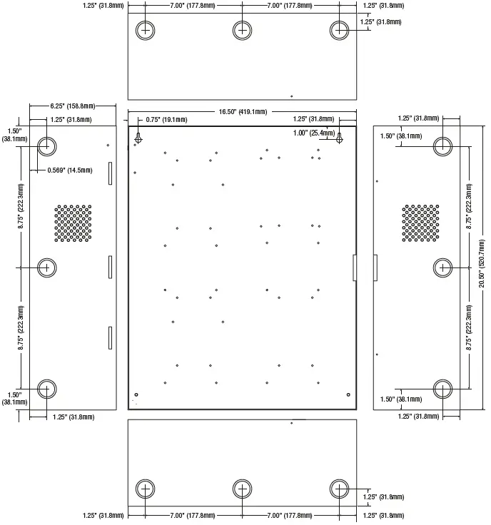
Enclosure dimensions (H x W x D): 20.5” x 16.5” x 6.25” (520.7mm x 419.1mm x 158.8mm).
MaxFit E Installation Instructions:
Wiring methods shall be in accordance with the National Electrical Code/NFPA 70/NFPA 72/ANSI, The Canadian Electrical Code, Part 1 and with all local codes and authorities having jurisdiction. The product must be located indoors within the protected premises.
- Mount unit in desired location. Mark and predrill holes in the wall to line up with the top three keyholes in the enclosure. Install three upper fasteners and screws in the wall with the screw heads protruding. Place the enclosure’s upper keyholes over the three upper screws; level and secure. Mark the position of the lower three holes. Remove the enclosure. Drill the lower holes and install the three fasteners. Place the enclosure’s upper keyholes over the three upper screws. Install the three lower screws and make sure to tighten all screws (Enclosure Dimensions, pg. 8).
- Connect un switched AC power (115VAC 60Hz) to terminals marked [L, N] .
 Use 14 AWG or larger for all power connections. Secure green wire lead to earth ground. For Fire Alarm applications the outputs are “Special Applications” only. Keep power-limited wiring separate from non power-limited wiring (1150VAC 60Hz Input, Battery Wires). Minimum 0.25” spacing must be provided.
CAUTION:
Do not touch exposed metal parts.
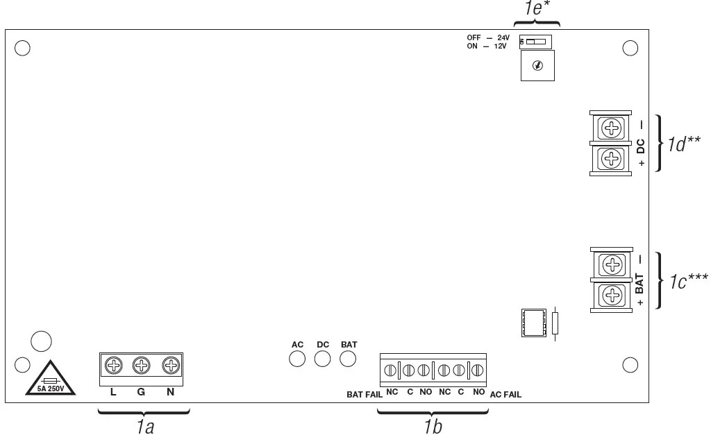
Shut branch circuit power before installing or servicing equipment. There are no user serviceable parts inside. Refer installation and servicing to qualified service personnel. - Select desired DC output voltage by setting SW1 to the appropriate position (MaxFit11E, MaxFit13E, MaxFit33E, MaxFit35E and MaxFit37E) .

- MaxFit55E power supplies are factory set at 12VDC. MaxFit77E power supplies are factory set at 24VDC (Stand-by Battery Specifications, pg. 5).
- Measure output voltage before connecting devices. This helps avoiding potential damage.
- Connect devices or Altronix sub-assembly modules to be powered to the terminals marked [– DC +] .Refer to page 2 for non power-limited applications.
- For Access Control applications batteries are optional. When batteries are not used, a loss of AC will result in the loss of output voltage. When the use of stand-by batteries is desired, they must be lead acid or gel type. Connect battery to the terminals marked [– BAT + ].Use two (2) 12VDC batteries connected in series for 24VDC operation (battery leads included). Use batteries – Casil CL1270 (12V/7AH), CL12120 (12V/12AH), CL12400 (12V/40AH), CL12650 (12V/65AH) batteries or UL recognized BAZR2 batteries of an appropriate rating.
- Connect appropriate signaling notification devices to AC FAIL & BAT FAIL supervisory relay outputs.
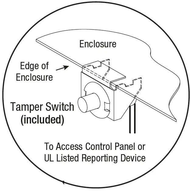
- For Access Control Applications: mount UL Listed tamper switch (Altronix Model TS112 or equivalent) at the top of the enclosure. Slide tamper switch bracket onto the edge or the enclosure approx. 2” from the right side .
 Connect tamper switch wiring to the Access Control Panel input or the appropriate UL Listed reporting device.
 - Please ensure that the cover is secured with the provided key lock.
 Use 14 AWG or larger for all power connections. Secure green wire lead to earth ground. For Fire Alarm applications the outputs are “Special Applications” only. Keep power-limited wiring separate from non power-limited wiring (1150VAC 60Hz Input, Battery Wires). Minimum 0.25” spacing must be provided.
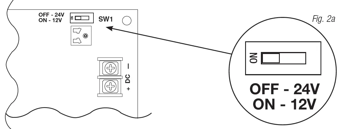
 Connect tamper switch wiring to the Access Control Panel input or the appropriate UL Listed reporting device.
Wiring:
Use 18 AWG or larger for all low voltage power connections.
Note:
Take care to keep power-limited circuits separate from non power-limited wiring (115VAC, Battery).
Maintenance:
Unit should be tested at least once a year for the proper operation as follows:
Output Voltage Test: Under normal load conditions the DC output voltage should be checked for proper voltage level (Power Supply Board Stand-by Battery Specifications, pg. 7).
Battery Test: Under normal load conditions check that the battery is fully charged, check specified voltage at the battery terminals and at the board terminals marked
[+ BAT –] to ensure that there is no break in the battery connection wires.
Note:
AL400ULXB2, AL600ULXB and AL1012ULXB Power Supply Board maximum charge current is 0.7A. AL1024ULXB2 Power Supply Board maximum charge current is 3.6A.
Expected battery life is 5 years, however it is recommended to change batteries within 4 years or less if necessary
Power Supply Board Output Voltage Settings:
Power Supply Board LED Diagnostics:
| LED | Power Supply Status | |
| Red (DC) | Green (AC) | |
| ON | ON | Normal operating condition. |
| ON | OFF | Loss of AC. Stand-by battery is supplying power. |
| OFF | ON | No DC output. Short circuit or thermal overload condition. |
| OFF | OFF | No DC output. Loss of AC. Discharged battery. |
| Red (Bat) | Battery Status |
| ON | Normal operating condition. |
| OFF | Battery fail/low battery. |
Terminal Identification:
| Terminal Legend | Function/Description |
| L, G, N | Connect 115VAC to these terminals: L to hot, N to neutral (Fig. 1a, pg. 4). |
| + DC – ** | Refer to MaxFit E Series Configuration Chart, pg 2. |
| AC FAIL NO, C, NC | Used to notify loss of AC power, e.g. connect to audible device or alarm panel. Relay normally energized when AC power is present. Contact rating 1A @ 28VDC. AC or brownout fail is reported within 1 minute of event. To delay reporting for up to 6 hrs., cut “AC Delay” jumper and reset power to unit (Fig. 1b, pg. 4). |
| BAT FAIL NO, C, NC | Used to indicate low battery condition, e.g. connect to alarm panel. Relay normally energized when DC power is present. Contact rating 1A @ 28VDC. A removed battery is reported within 1 minute. Battery reconnection is reported within 1 minute. Low battery threshold: approximately 21VDC (Fig. 1b, pg. 4). |
| + BAT – *** | Stand-by battery connections (Fig. 1c, pg. 4). MaxFit3E and MaxFit5E maximum charge current 0.7A. MaxFit7E maximum charge current 3.6A. |
- AL1012ULXB terminals marked [– DC +]
- AL1024ULXB2 terminals marked [– BAT +]
Power Supply Board Stand-by Battery Specifications
| Altronix Model | Power Supply Board | Battery | 20 min. of Backup | 4 hr. of Backup | 24 hr. of Backup | 60 hr. of Backup |
| MaxFit11E MaxFit13E | AL400ULXB2 (Refer to Fig. 2a on pg. 4 for Switch [SW1] location and position) | 12VDC/40AH* | N/A | 4A | 1A | 300mA |
| 24VDC/12AH | N/A | 200mA | N/A | N/A | ||
| 24VDC/40AH* | N/A | 3A | 1A | 300mA | ||
| MaxFit13E MaxFit33E MaxFit35E MaxFit37E | AL600ULXB (Refer to Fig. 2a, on pg. 4 for Switch [SW1] location and position) | 12VDC/40AH* | N/A | 6A | 1A | 300mA |
| 24VDC/12AH | N/A | 200mA | N/A | N/A | ||
| 24VDC/40AH* | N/A | 6A | 1A | 300mA | ||
| MaxFit35E MaxFit55E MaxFit75E | AL1012ULXB (Factory set at 12VDC) | 12VDC/12AH | 10A | Battery capacity for emergency stand-by at least 20 mins. | N/A | N/A |
| MaxFit37E MaxFit75E MaxFit77E | AL1024ULXB2 (Factory set at 24VDC) | 24VDC/12AH | 8A | 1.5A | 200mA | 100mA |
| 24VDC/65AH* | N/A | 8A | 1.5A | 500mA |
Note:
Additional battery enclosure required.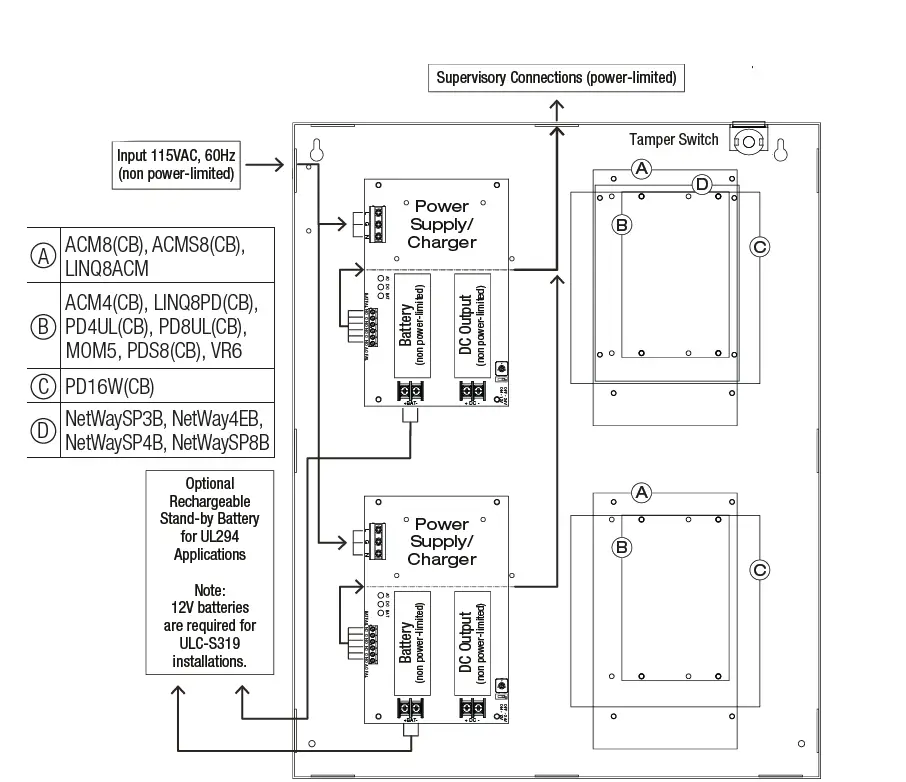 NEC Power-Limited Wiring Requirements:
Power-limited and non power-limited circuit wiring must remain separated in the cabinet. All power-limited circuit wiring must remain at least 0.25” away from any non power-limited circuit wiring. Furthermore, all power-limited circuit wiring and non power-limited circuit wiring must enter and exit the cabinet through different conduits. One such example of this is shown below. Your specific application may require different conduit knockouts to be used. Any conduit knockouts may be used. For power-limited
applications use of conduit is optional. All field wiring connections must be made employing suitable gauge CM or FPL jacketed wire (or equivalent substitute). Optional battery enclosure must be mounted adjacent to the power supply via Class 1 wiring methods. For Canadian installations use shielded wiring for all connections.
Note:
Refer to wire handling drawing below for the proper way to install the CM or FPL jacketed wire.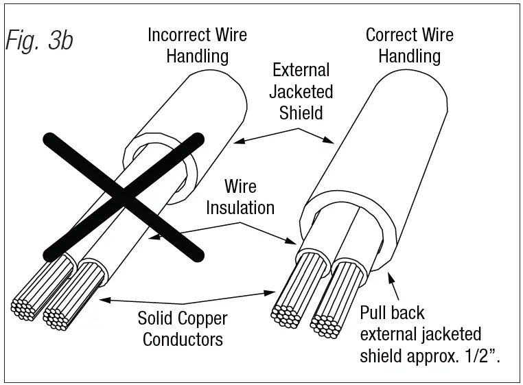 CAUTION:
When power supply board is set for 12VDC use only one (1) 12VDC stand-by battery. Connect red battery lead to the terminal marked [+ BAT] and to the [positive (+)] terminal of the battery. Connect black battery lead to terminal marked [BAT –] and to the [negative (–)] terminal of the battery.
Keep power-limited wiring separate from non power-limited. Use minimum 0.25″ spacing.
12AH Rechargeable batteries are the largest batteries that can fit in this enclosure. An external battery enclosure must be used if using the 40AH or 65AH batteries.
MaxFit Enclosure Dimensions (approximate):
20.5” x 16.5” x 6.25” (520.7mm x 419.1mm x 158.8mm)