![]()
Mounting instruction and
User manual
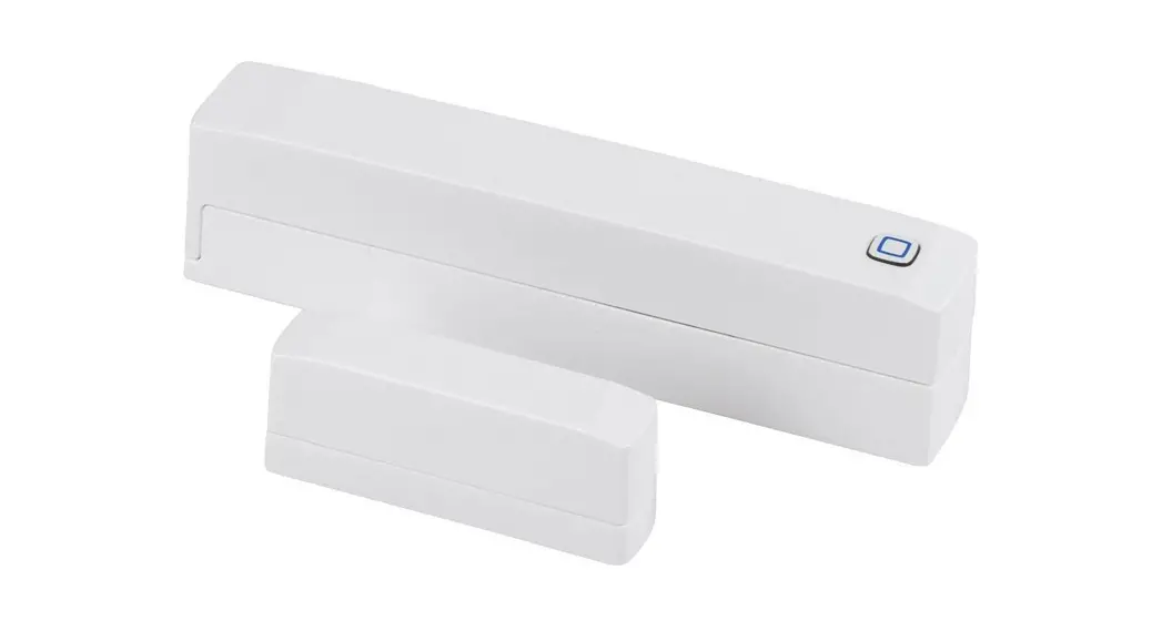
Window and Door Contact with magnet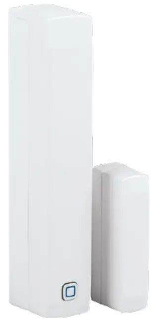
HYIP-SWDM
 |  |
 |  |
 |  |
 |  |
Package contents
| Quantity | Description |
| 1 | Homematic IP Window/Door Contact with magnet |
| 1 | Magnet contact and spacer |
| 2 | Double-sided adhesive strips |
| 2 | Countersunk head screws 2.2 x 13 mm |
| 2 | Countersunk head screws 2.2 x 16 mm |
| 2 | 1.5 V LR03/micro/AAA batteries |
| 2 | Operating manuals |
| 1 | Supplement sheet with safety instructions |
Documentation © 2019 eQ-3 AG, Germany
All rights reserved. Translation from the original version in German. This manual may not be reproduced in any format, either in whole or in part, nor may it be duplicated or edited by electronic, mechanical, or chemical means, without the written consent of the publisher.
Typographical and printing errors cannot be excluded. However, the information contained in this manual is reviewed on a regular basis and any necessary corrections will be implemented in the next edition. We accept no liability for technical or typographical errors or the consequences thereof. All trademarks and industrial property rights are acknowledged. Printed in Hong Kong
Changes may be made without prior notice as a result of technological advances. 154601 (web) Version 1.1 (12/2021) 34
Information about this manual
Please read this manual carefully before beginning operation with your Homematic IP components. Keep the manual so you can refer to it at a later date if you need to. If you hand over the device to other persons for use, please hand over this manual as well.![]() Symbols used: Attention! This indicates a hazard.
Symbols used: Attention! This indicates a hazard.![]() Please note: This section contains important additional information.
Please note: This section contains important additional information.
Hazard information
![]() Do not open the device. It does not contain any parts that can be maintained by the user. In the event of an error, please have the device checked by an expert.
Do not open the device. It does not contain any parts that can be maintained by the user. In the event of an error, please have the device checked by an expert.![]() We do not assume any liability for damage to property or personal injury caused by improper use or the failure to observe the hazard information. In such cases, any claim under warranty is extinguished! For consequential damages, we assume no liability!
We do not assume any liability for damage to property or personal injury caused by improper use or the failure to observe the hazard information. In such cases, any claim under warranty is extinguished! For consequential damages, we assume no liability!![]() For safety and licensing reasons (CE), unauthorized change and/or modification of the device is not permitted.
For safety and licensing reasons (CE), unauthorized change and/or modification of the device is not permitted.![]() The device may only be operated in dry and dust-free environment. It must be protected from the effects of moisture, vibrations, solar or other methods of heat radiation, cold and mechanical loads.
The device may only be operated in dry and dust-free environment. It must be protected from the effects of moisture, vibrations, solar or other methods of heat radiation, cold and mechanical loads.![]() The device is not a toy; do not allow children to play with it. Do not leave packaging material lying around. Plastic films/bags, pieces of polystyrene, etc. can be dangerous in the hands of a child.
The device is not a toy; do not allow children to play with it. Do not leave packaging material lying around. Plastic films/bags, pieces of polystyrene, etc. can be dangerous in the hands of a child.![]() The device is only intended for use within residential, business and commercial areas as well as in small enterprises.
The device is only intended for use within residential, business and commercial areas as well as in small enterprises.![]() Using the device for any purpose other than that described in this operating manual does not fall within the scope of intended use and shall invalidate any warranty or liability.
Using the device for any purpose other than that described in this operating manual does not fall within the scope of intended use and shall invalidate any warranty or liability.
Function and device overview
The Homematic IP Window / Door Contact reliably detects open windows and doors via an integrated magnetic sensor. The device is easily mounted thanks to the supplied adhesive strips or screws.
You can directly connect the window and door contact to the Homematic IP Radiator Thermostat basic and automatically reduce the room temperature during ventilation.
Alternatively, you can use the device in conjunction with a Homematic IP Access Point and integrate it comfortably into the Homematic IP smart home system. Via the free smartphone app, it can be used with comprehensive climate control and security applications. Open windows and doors are immediately displayed in the Homematic IP app. Thus, even while being out and about you can keep a close eye on your windows and doors.
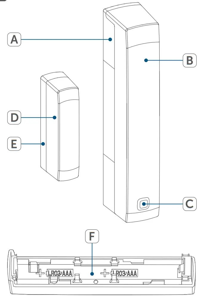
Device overview (see figure 1):
(A) Bracket
(B) Electronic unit
(C) System button (teach-in button and LED)
(D) Magnetic contact
(E) Spacer (6 mm) for magnetic contact
(F) Battery compartment
General system information
This device is part of the Homematic IP smart home system and works with the Homematic IP protocol. All devices of the system can be configured comfortably and individually with the user interface of the Central Control Unit CCU3 or flexibly via the Homematic IP smartphone app in connection with the Homematic IP cloud. All available functions provided by the system in combination with other components are described in the Homematic IP Wired Installation Guide. All current technical documents and updates are provided at www.homematic-ip.com.
Start-up
5.1 Teaching-in![]() Please read this entire section before starting the teach-in procedure.
Please read this entire section before starting the teach-in procedure.
You can either pair the device directly with one Homematic IP Radiator Thermostat basic or connect it to the Homematic IP Access Point (HmIP-HAP). After pairing, the configuration has to be done directly on the device. After connecting to the Access Point, the configuration is done via the Homematic IP app.
5.1.1 Direct pairing with a Homematic IP device![]() You can connect the Homematic IP Window and Door Contact with a magnet (HmIP-SWDM) to a Homematic IP Radiator Thermostat basic (HmIP-eTRV-B).
You can connect the Homematic IP Window and Door Contact with a magnet (HmIP-SWDM) to a Homematic IP Radiator Thermostat basic (HmIP-eTRV-B).![]() Please make sure you maintain a distance of at least 50 cm between the devices.
Please make sure you maintain a distance of at least 50 cm between the devices.![]() You can cancel the pairing procedure by briefly pressing the system button (C) again. This will be indicated by the device LED (C) lighting up red.
You can cancel the pairing procedure by briefly pressing the system button (C) again. This will be indicated by the device LED (C) lighting up red.
To connect the device with another Homematic IP device, the pairing mode of both devices has to be activated. To do this, please proceed as follows:
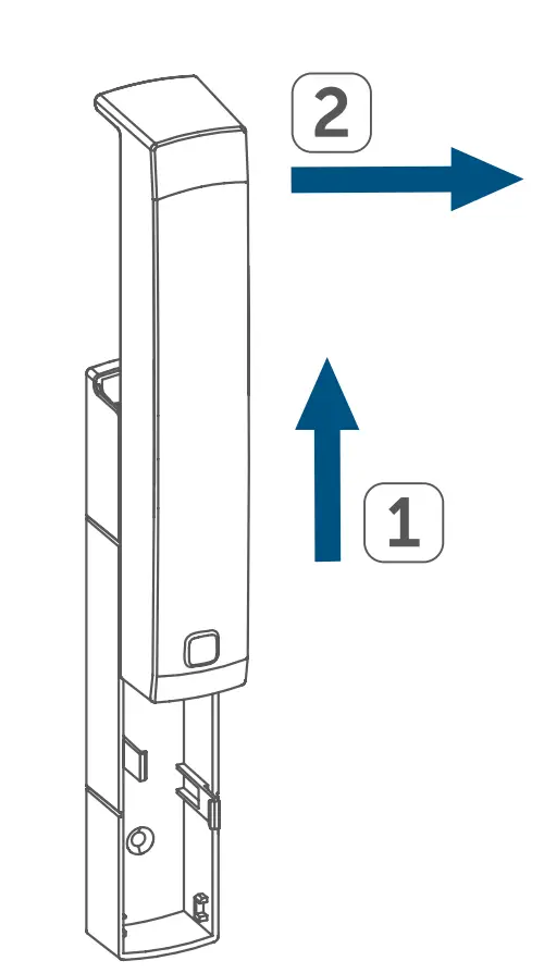
- Loosen the electronic unit (B) from the bracket (A) by pushing it upwards and removing it to the front (see figure 2).
- Remove the insulation strip from the battery compartment (F) of the window/door contact.
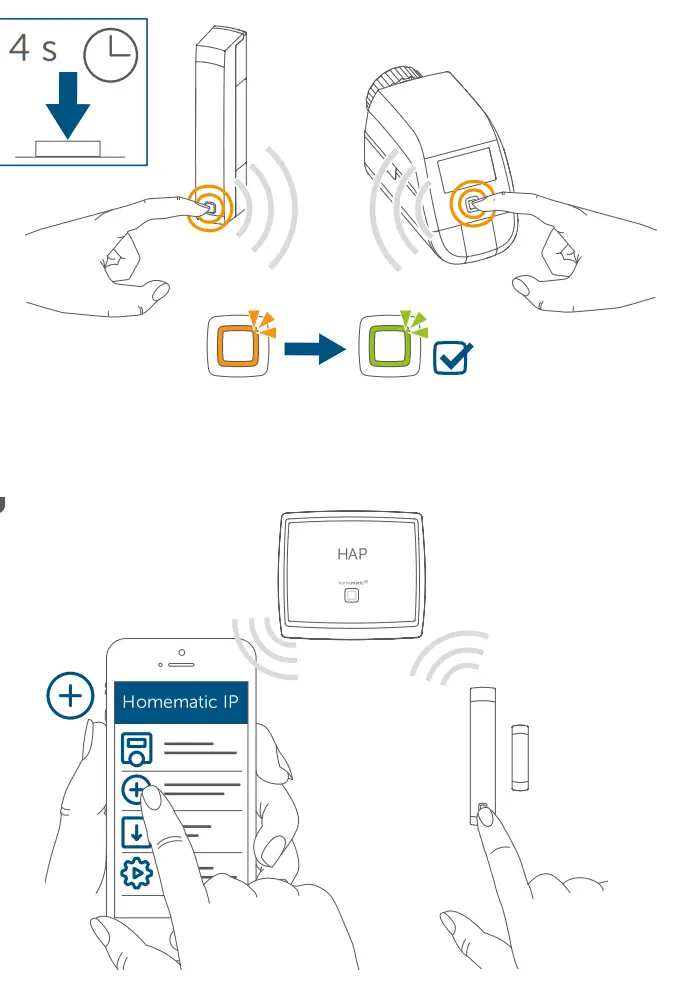
- Press and hold down the system button (C) for at least 4 seconds to activate the teach-in mode (see figure 3). The device LED (C) starts to flash orange. Pairing mode remains activated for 3 minutes.
- Press and hold down the system button of the device you want to connect (e.g. the Homemadeic IP Radiator Thermostat basic) for at least 4 seconds to activate the pairing mode (see figure 3). The device LED starts to flash orange. For further information, please refer to the operating manual of the corresponding device.
The device LED lights up green to indicate that the pairing has been successful. If pairing failed, the device LED lights up red. Please try again.![]() If no pairing operations are carried out, pairing mode is exited automatically after 3 seconds.
If no pairing operations are carried out, pairing mode is exited automatically after 3 seconds.![]() If you want to add another device first activate the pairing mode of the existing device and afterward the pairing mode of the new device.
If you want to add another device first activate the pairing mode of the existing device and afterward the pairing mode of the new device.![]() If, for example, you want to add another radiator thermostat, first pair the new radiator thermostat to the existing radiator thermostat. Afterward, you can pair the new radiator thermostat with the existing window/door contact.
If, for example, you want to add another radiator thermostat, first pair the new radiator thermostat to the existing radiator thermostat. Afterward, you can pair the new radiator thermostat with the existing window/door contact.![]() If you are using several devices in one room, you should pair all devices with each other.
If you are using several devices in one room, you should pair all devices with each other.
5.1.2 Teaching-in to the Access Point (alternative)![]() First set up your Homematic IP Access Point via the Homematic IP app to enable the operation of other Homematic IP devices within your system. For further information, please refer to the operating manual of the Access Point.
First set up your Homematic IP Access Point via the Homematic IP app to enable the operation of other Homematic IP devices within your system. For further information, please refer to the operating manual of the Access Point.![]() You can connect the device either to the Access Point or to the Homematic Central Control Unit CCU2/CCU3. For detailed information, please refer to the Homematic
You can connect the device either to the Access Point or to the Homematic Central Control Unit CCU2/CCU3. For detailed information, please refer to the Homematic ![]() IP User Guide, available for download in the download area of www.homematic-ip.com.
IP User Guide, available for download in the download area of www.homematic-ip.com.
To integrate the device into your system and to enable control via the free Homematic IP app, you must connect the device to your Homematic IP Access Point first.
To connect the device, please proceed as follows:
- Open the Homematic IP app on your smartphone.
- Select the menu item “Teach-in device”.
- Loosen the electronic unit (B) from the bracket (A) by pushing it upwards and removing it to the front (see figure 2).
- Remove the insulation strip from the battery compartment (F) of the window/door contact. Teach-in mode remains activated for 3 minutes.
![]() You can manually start the teach-in mode for another 3 minutes by pressing the system button (C) shortly (see figure 4).
You can manually start the teach-in mode for another 3 minutes by pressing the system button (C) shortly (see figure 4).
- Your device will automatically appear in the Homematic IP app.
- To confirm, please enter the last four digits of the device number (SGTIN) in your app or scan the QR code. Therefore, please see the sticker supplied or attached to the device.
- Wait until the teach-in is completed.
- If the teaching-in was successful, the LED (C) lights up green. The device is now ready for use.
![]() If the LED lights up red, please try again.
If the LED lights up red, please try again.
- Select, in which application (e.g. climate control and/or security) you would like to use the device.
- In the app, give the device a name and allocate it to a room.
5.2 Mounting![]() Read this entire section before starting to mount the device.
Read this entire section before starting to mount the device.
5.2.1 Selecting a suitable mounting location
- Select a window or door for mounting the window/door contact.
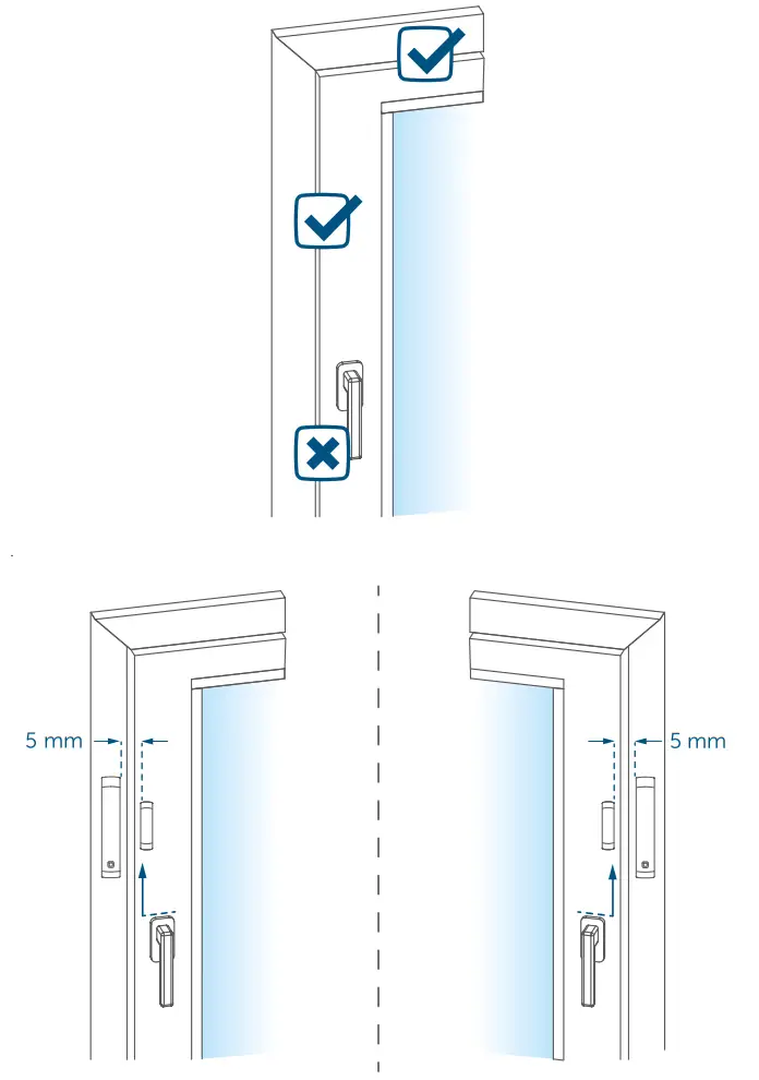
- Fix one part of the window/door contact (magnetic contact (I) or electronic unit (K)) to the moving part (door or window wing), the other one at the stationary part (frame) of the window or door (see figure 5).
- Fasten the window/door contact on the side of the window or door where the handle is located, in the upper third of the window/door frame (see figure 5) (for fastening see “5.2.2 Adhesive strip or screw mounting” on page 45).
- The magnetic contact can be mounted in a horizontal or vertical way, left or right to the electronic unit of the window/door contact.
![]() The electronic unit and the magnetic contact should be mounted at the same height. Since a spacer (E) can be used for the magnetic contact to raise it, the electronic unit must be mounted on the higher part of the window.
The electronic unit and the magnetic contact should be mounted at the same height. Since a spacer (E) can be used for the magnetic contact to raise it, the electronic unit must be mounted on the higher part of the window.![]() The ideal spacing between the housing edge of the window/door contact and the magnet contact should be 5 mm (see figure 5).
The ideal spacing between the housing edge of the window/door contact and the magnet contact should be 5 mm (see figure 5).
5.2.2 Adhesive strip or screw mounting
You can use
- the double-sided adhesive strip or
- countersunk head screws to fix the device to the window/door frame.
![]() Do not yet assemble the magnetic contact before screw mounting.
Do not yet assemble the magnetic contact before screw mounting.
Adhesive strip mounting
For mounting the device using the adhesive strips, please proceed as follows:
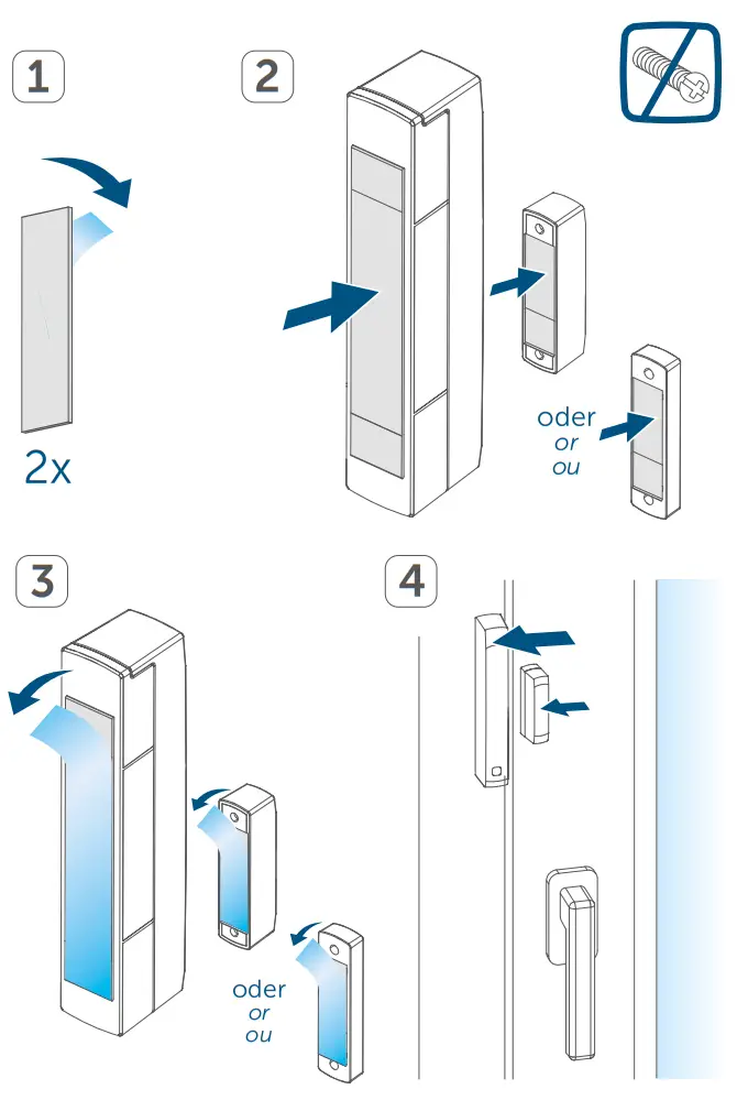
- Attach the large double-sided adhesive strip to the backside of the bracket (A) (see figure 6) and press the device to the desired position on the window.
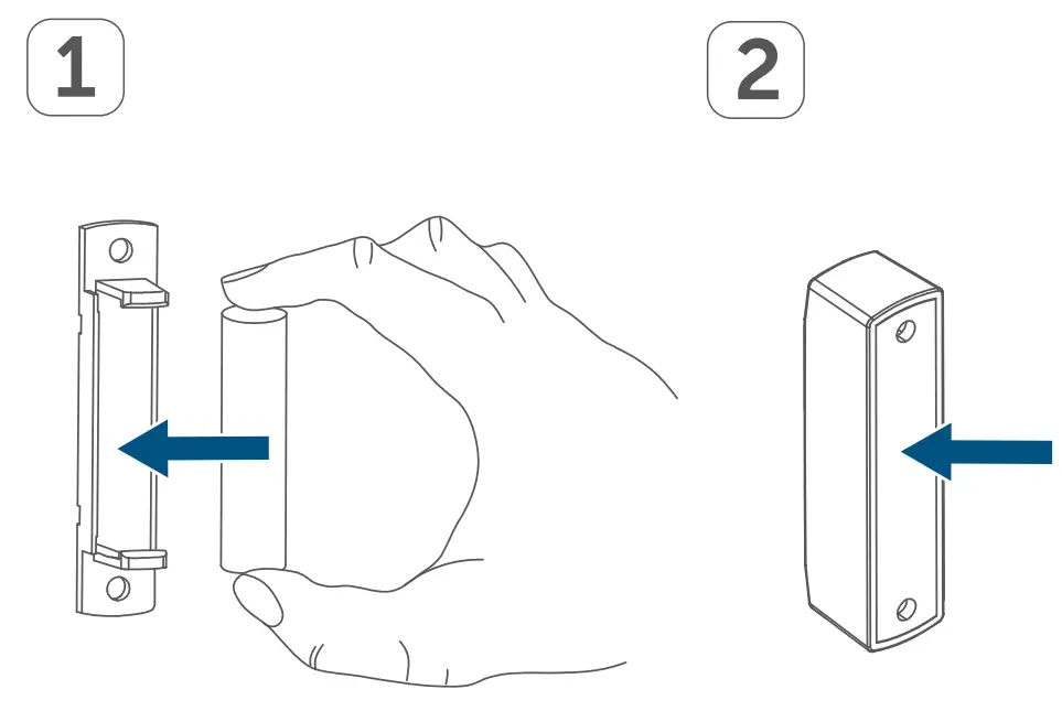
- Place the magnet in the bracket at the backside and place the backside into the housing of the magnetic contact (see figure 7).
 When using the spacer (E), fasten the smaller adhesive strip at the backside of the spacer (see figure 6) and attach it to the desired position on the window. Afterward, place the magnet contact onto the spacer.
 - Attach the small double-sided adhesive strip to the backside of the magnet contact (D) (see fig. 6) and press the magnetic contact onto the desired position of the window.Make sure that the mounting surface is smooth, solid, non-disturbed, free of dust, grease, and solvents, and not too cold to ensure long-time adherence.
Screw mounting
![]() Using screws will damage the window and/or door. For those living in rented accommodation, this could lead to a landlord making claim for compensation or holding back a tenant’s deposit.
Using screws will damage the window and/or door. For those living in rented accommodation, this could lead to a landlord making claim for compensation or holding back a tenant’s deposit.![]() Do not yet assemble the magnetic contact before screw mounting.
Do not yet assemble the magnetic contact before screw mounting.
For mounting the device using screws proceed as follows:
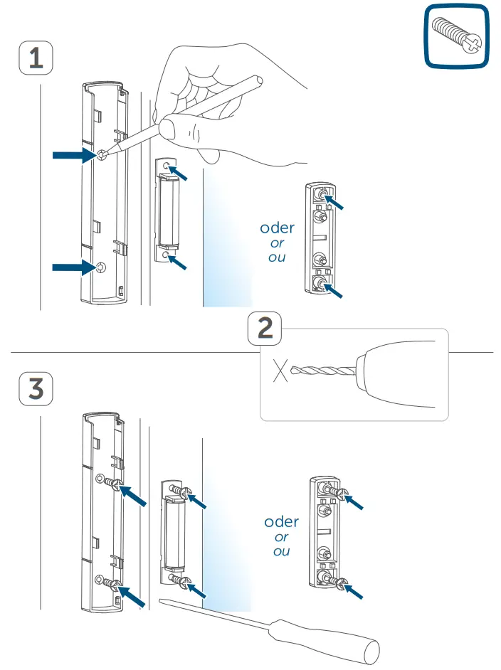
- Pre-drill the screw holes in the brackets (A) using an appropriate drill.
- Mark the screw holes for the electronic unit (B) according to the bracket (A) on the window (see figure 8).
- Mark the screw holes for the magnetic contact (D) or, if required, for the spacer (E) on the window (see figure 8).
- If you are working with hard surfaces you should pre-drill the holes marked using a 1.5 mm drill (not necessary for soft surfaces).
- Place the bracket of the electronic unit to the desired mounting location and turn the two longer countersunk screws (2.2 x 16 mm) into the screw holes (see figure 8).
- Insert the electronic unit into the bracket.
- Place the backside of the magnetic contact or the spacer to the desired mounting location and turn the two smaller countersunk screws (2.2 x 13 mm) into the screw holes (see figure 8).
- Place the magnet in the bracket at the backside and place the backside into the housing of the magnetic contact (see figure 7).
![]() When using the spacer, you can simply attach the magnetic contact after installation to the spacer.
When using the spacer, you can simply attach the magnetic contact after installation to the spacer.
Replacing batteries
If an empty battery is displayed via the app or the device (see “7.4 Error codes and flashing sequences” on page 50), replace the used batteries by two new LR03/ micro/AAA batteries. You must observe the correct battery polarity.
To replace the batteries, please proceed as follows:
- Loosen the bracket (A) from the electronic unit (B) by sliding it down and removing it to the back (see figure 2).
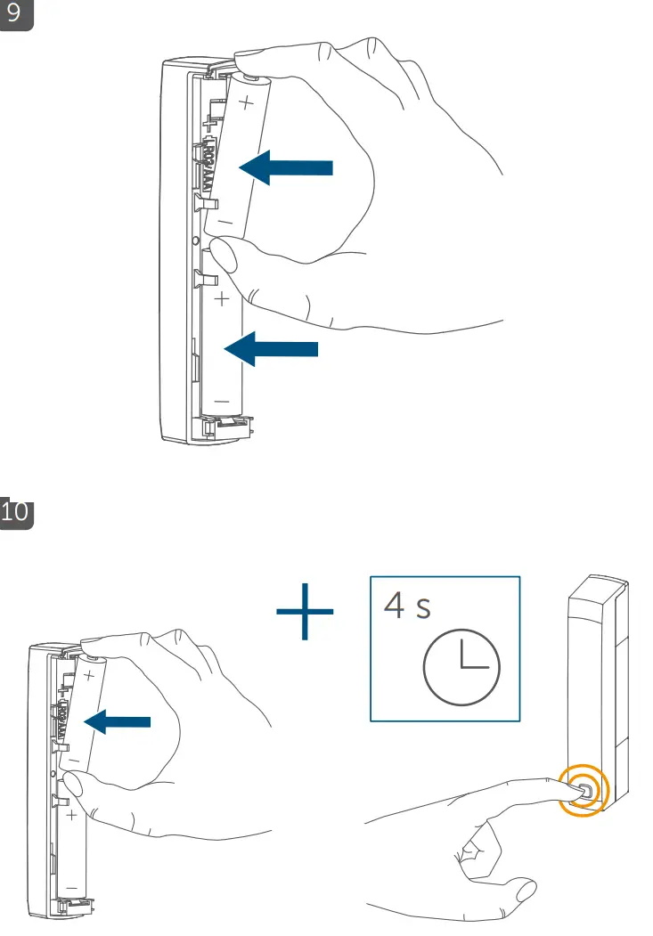
- Insert two new 1.5 V LR03/micro/batteries into the battery compartment (F), making sure that you insert them the right way round (see figure 9).
- Pay attention to the flashing signals of the device LED while inserting the batteries (see “7.4 Error codes and flashing sequences” on page 50).
- Put the bracket back to the electronic unit.
Once the batteries have been inserted, the device will perform a self-test (approx. 2 seconds). Afterward, initialization is carried out. The LED test display will indicate that initialization is complete by lighting up orange and green.
 Used batteries should not be disposed of with regular domestic waste! Instead, take them to your local battery disposal point.
![]() Never recharge standard batteries. Do not throw the batteries into a fire! Do not expose batteries to excessive heat. Do not short-circuit batteries. Doing so will present a risk of explosion.
Never recharge standard batteries. Do not throw the batteries into a fire! Do not expose batteries to excessive heat. Do not short-circuit batteries. Doing so will present a risk of explosion.
Troubleshooting
7.1 Weak batteries
Provided that the voltage value permits it, the window/door contact will remain ready for operation also if the battery voltage is low. Depending on the particular load, it may be possible to send transmissions again repeatedly, once the batteries have been allowed a brief recovery period.
If the voltage drops too far during transmission, this will be displayed on the device or via the Homematic IP app (see “7.4 Error codes and flashing sequences” on page 50). In this case, replace the empty batteries with two new batteries (see “6 Replacing batteries” on page 47).
7.2 Command not confirmed
If at least one receiver does not confirm a command, the device LED (C) lights up red at the end of the failed transmission process. The failed transmission may be caused by radio interference (see “10 General information about radio operation” on page 53). The failed transmission may also be caused by the following:
- The receiver cannot be reached.
- The receiver is unable to execute the command (load failure, mechanical blockade, etc.).
- The receiver is defective.
7.3 Duty cycle
The duty cycle is a legally regulated limit of the transmission time of devices in the 868 MHz range. The aim of this regulation is to safeguard the operation of all devices working in the 868 MHz range.
In the 868 MHz frequency range we use, the maximum transmission time of any device is 1% of an hour (i.e. 36 seconds in an hour). Devices must cease transmission when they reach the 1% limit until this time restriction comes to an end. Homematic IP devices are designed and produced with 100% conformity to this regulation. During normal operation, the duty cycle is not usually reached. However, repeated and radio-intensive teaching processes mean that it may be reached in isolated instances during start-up or initial installation of a system. If the duty cycle is exceeded, this is indicated by one long red flashing of the device LED (C), and may manifest itself in the device temporarily working incorrectly. The device starts working correctly again after a short period (max. 1 hour).
7.4 Error codes and flashing sequences
| Flashing code | Meaning | Solution |
| Short orange flashing | Radio trans-mission/send attempt/data transmission | Wait until the transmission is completed. |
| lx long green lighting | Transmission confirmed | You can continue operation. |
| lx long red lighting | Transmission failed or duty cycle limit is reached | Please try again (see sec. “7.2 Command not confirmed” on page 49 or “7.3 Duty cycle” on page 50). |
| Short orange flashing (every 10 s) | Teach-in mode active | Please enter the last four numbers of the device serial number to confirm (see “5.1 Teaching-in” on page 39). |
| Fast orange flashing | Pairing mode active | Activate the pairing mode of the device you want to connect (“5.1.1 Direct pairing with a Homematic IP device” on page 40). |
| Short orange lighting (after green or red confirmation) | Batteries empty | Replace the batteries of the device (see “6 Replacing batteries” on page 47). |
| Long and short orange flashing (alternating) | Update of de- vice software (OTAU) | Wait until the update is completed. |
| 6x long red flashing | Device defective | Please see your app for error messages or contact your retailer. |
| lx orange, lx green lighting (after inserting batteries) | Test display | Once the test display has stopped, you can continue. |
Restore factory settings
![]() The factory settings of the device can be restored. If you do this, you will lose all your settings.
The factory settings of the device can be restored. If you do this, you will lose all your settings.
To restore the factory settings of the device, please proceed as follows:
- Loosen the electronic unit (B) from the bracket (A) by pushing it upwards and removing it to the front (see figure 2).
- Remove a battery.
- Insert the battery ensuring that the polarity is correct and press and hold down the system button (C) for 4 s at the same time until the LED (C) will quickly start flashing orange (see figure 10).
- Release the system button again.
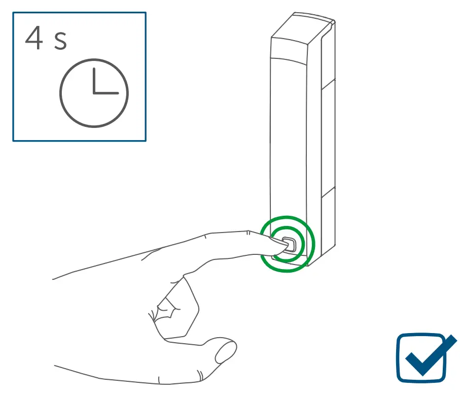
- Press and hold down the system button again for 4 seconds, until the LED lights up green (see figure 11). · Release the system button to finish the procedure. The device will perform a restart.
Maintenance and cleaning
![]() The device does not require you to carry out any maintenance other than replacing the battery when necessary. Enlist the help of an expert to carry out any maintenance or repairs.
The device does not require you to carry out any maintenance other than replacing the battery when necessary. Enlist the help of an expert to carry out any maintenance or repairs.
Clean the device using a soft, lint-free cloth that is clean and dry. You may dampen the cloth a little with lukewarm water in order to remove more stubborn marks. Do not use any detergents containing solvents, as they could corrode the plastic housing and label.
General information about radio operation
Radio transmission is performed on a non-exclusive transmission path, which means that there is a possibility of interference occurring. Interference can also be caused by switching operations, electrical motors, or defective electrical devices.![]() The range of transmission within buildings can differ greatly from that available in the open air. Besides the transmitting power and the reception characteristics of the receiver, environmental factors such as humidity in the vicinity have an important role to play, as do on-site structural/ screening conditions
The range of transmission within buildings can differ greatly from that available in the open air. Besides the transmitting power and the reception characteristics of the receiver, environmental factors such as humidity in the vicinity have an important role to play, as do on-site structural/ screening conditions
Hereby, eQ-3 AG, Marburger Str. 29, 26789 Leer/Germany declares that the radio equipment type Homematic IP HmIP-SWDM is in compliance with Directive 2014/53/ EU. The full text of the EU declaration of conformity is available at the following internet address: www.homematic-ip.com
Technical specifications
Device short name:……………………HYIP-SWDM
Supply voltage:………………………………. 2x 1.5 V LR03/micro/AAA
Current consumption:…………………………… 35 mA max.
Battery life: ………………………………………….4 years (Typ.)
Degree of protection: …………………………..IP20
Ambient temperature: ………………..-10 to +50 °C
Dimensions electronic unit (W x H x D):……………………………….102 x 18 x 25 mm
Dimensions magnet contact (W x H x D):…………………………..48 x 11 x 13 mm
Weight electronic unit:…………………………………46 g (including batteries)
Weight magnetic contact:………………………….. 17 g (including magnet)
Radiofrequency band:………………..868.0-868.6 MHz 869.4-869.65 MHz
Maximum radiated power:…………………………….10 dBm
Receiver category:……………………………………SRD category 2
Typical open area RF range:…………………………………….200 m
Duty cycle: …………………………….< 1 % per h/< 10 % per h
Subject to technical changes.
Instructions for disposal
Do not dispose of the device with regular domestic waste! Electronic equipment must be disposed of at local collection points for waste electronic equipment in compliance with the Waste Electrical and Electronic Equipment Directive.
Information about conformity![]() The CE sign is a free trading sign addressed exclusively to the authorities and does not include any warranty of any properties.
The CE sign is a free trading sign addressed exclusively to the authorities and does not include any warranty of any properties.![]() For technical support, please contact your specialist dealer.
For technical support, please contact your specialist dealer.
Kostenloser Download der Homematic IP App! Free download of the Homematic IP app!
 https://itunes.apple.com/de/app/homematic-ip/id1012842369?mt=8 https://itunes.apple.com/de/app/homematic-ip/id1012842369?mt=8 |  https://play.google.com/store/apps/details?id=de.eq3.pscc.android&hl=de |
Bevollmächtigter des Herstellers: Manufacturer’s authorised representative:
eQ-3 AG Maiburger Straße 29 26789 Leer / GERMANY
www.eQ-3.de


