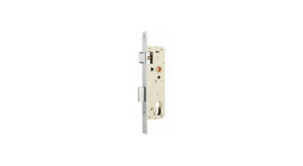
![]() A0400SSSM NARROW STILE MORTICE LOCK
A0400SSSM NARROW STILE MORTICE LOCK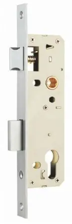
Installation Instructions
HANDING OF DOOR
RIGHT-HAND DOOR
| OUTSIDE DOOR OPENING IN | |
| OUTSIDE DOOR OPENING OUT |
LEFT-HAND DOOR
 | OUTSIDE DOOR OPENING IN |
 | OUTSIDE DOOR OPENING OUT |
IMPORTANT:
Before drilling the door, ensure correct handing is being installed
NOTE:
The case does not need to be opened at any time to change the function or handling of this lock
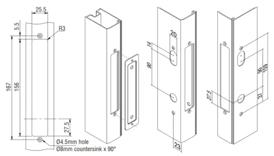
DOOR PREPARATION
METAL DOOR PREPARATION
- Determine the height of the lockset on the door
- Cut out the mortice window 156mm x 25.5mm with 3mm radius corners
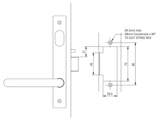
- Place template in opening and drill 4.5mm holes, countersink with 8mm dia at 90°
- Drill other appropriate holes for the selected lockset. Dimensions in the illustration suit a 23mm backset lock
- Do not drill holes all the way through to avoid door damage or incorrect installation
NOTE: Ensure the door furniture supplied matches the correct hole dimensions being drilled.
LOCK PREPARATION
CHECK LOCK STATUS
Ensure that the locking bar is in the unlocked position (UP). If the position needs to be changed to the unlock position, use a small flat blade screwdriver, to lever out the plastic cylinder hole plug (where fitted) and lift the locking bar using the screwdriver.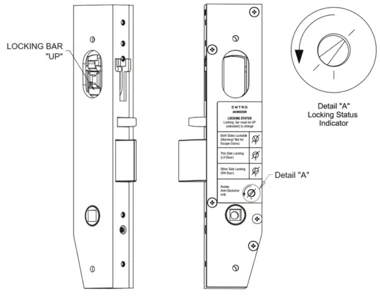 LOCK FUNCTIONS
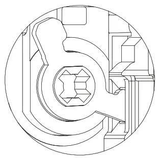
Depending on the locking function required it can be set to any vestibule or combination lock status. To change the locking function, use a small flat blade screwdriver to rotate (AntiClockwise Only) the locking wedge to the desired location. Refer to the Locking Status label on the lock body for further detail.
LOCKING STATUS
The locking bar must be UP (unlocked) to change
 | Both Side Lockable (Warning! Not suitable for Escape Doors) |
 | Other Side Locking (Right-Hand Doors) |
 | This Side Locking (Left Hand Doors) |
 | Rotate AntiClockwise Only |
REVERSE BOLT HEAD FOR HANDING
Determine lock handing from the Handing of Door chart. Rotate bolt head if required by removing Face Plate to pull and rotate the bolt 180° to suit the Latching direction.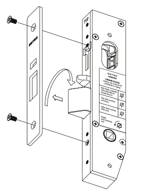 TURN ADAPTOR INSTALLATION
ENTRO turn adaptors are captive adaptors and must be installed correctly for proper lock operation.
- Determine to hand for adaptor
- Put lock into LOCKED STATUS by moving locking bar in down position.
- Insert adaptor ensuring the cam plate is engaged with the locking bar.
- Insert retaining pin and test operation, ensuring the locking bar is operating up & down with operation of cam (Maximum ¼ turn left or right).
- Lock can now be left in UNLOCKED STATUS with lock bar UP until installed on door.

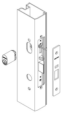
LOCK INSTALLATION
| FIT LOCK Insert Lock into the door and secure with 2 screws. | LOCKS WITH CYLINDERS
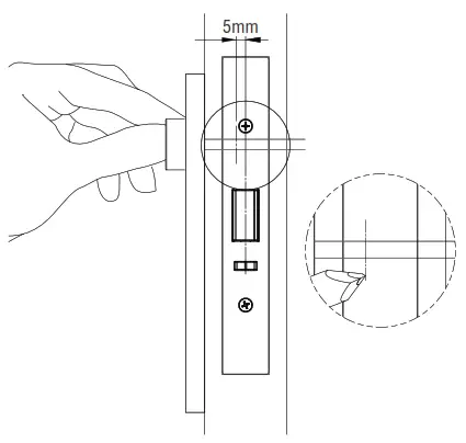
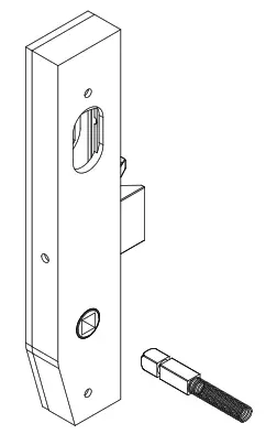
| LOCK WITHOUT CYLINDER Install faceplate and secure with 2 screws.LOCKS WITH TURN SNIB Mark and cut the connecting bar as shown. The turn snib must be in the vertical position when unlocked. 5mm | LOCKS FOR DOOR LEVERS WITH SPINDLES Insert spindle/s into the lock as required, ensuring the spindle spring is attached to the rear of the spindle before assembling. |
 |  |  |  |
DOOR FURNITURE INSTALLATION
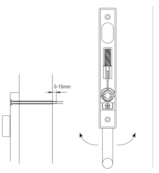
FIT FURNITURE
Rotate handle to the desired handing as shown. Ensure furniture screws are minimum 5mm and a maximum 15mm past the door face. Position furniture plates and secure them with mounting screws.
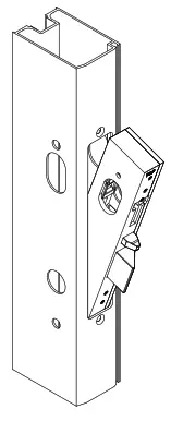
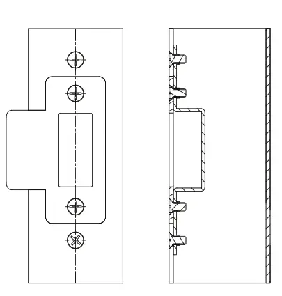
 FIT MOUNTING STRIKE
- Prepare doorjamb cutout and fit Strike Box to frame.
- Fit Strike to Strike Box and secure with 2 screws.

![]() A0400SSSM NARROW STILE MORTICE LOCK
A0400SSSM NARROW STILE MORTICE LOCK
www.entro.com.au


