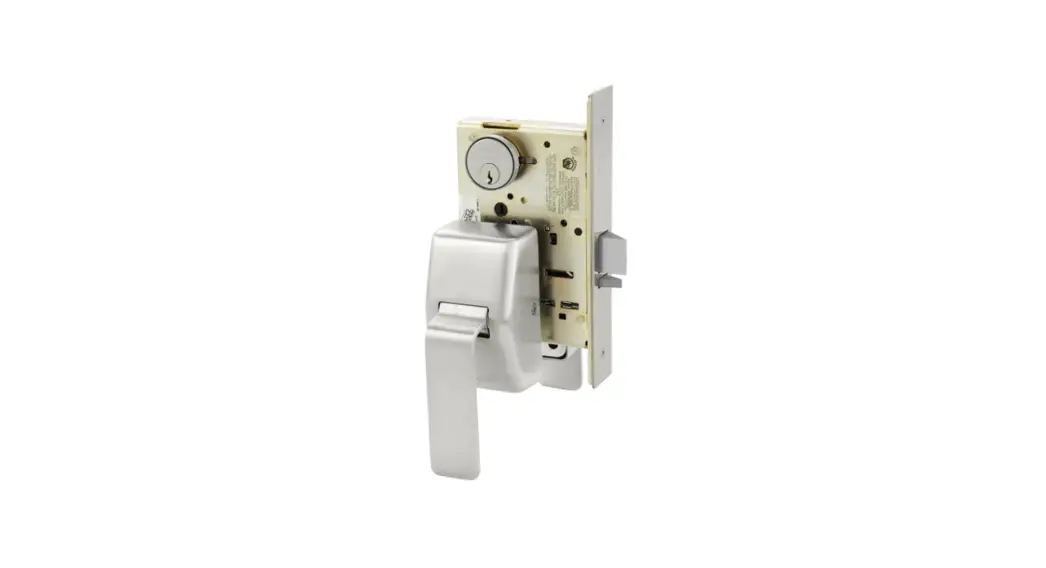
![]() 7800 Mortise Lock
7800 Mortise Lock
Instruction Manual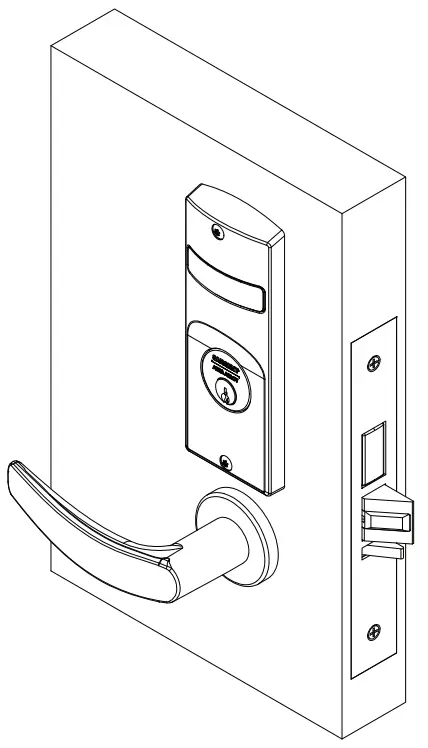
Installation Instructions
7800 & 8200 Series Mortise Lock
Used with Sectional Trim and V Series Indicators
7800 Mortise Lock
Tools Required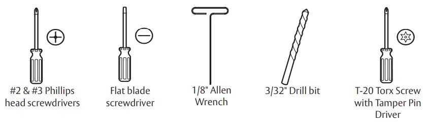
Indicator Variants
Depending on function and option ordered, indicators are provided in the following variations, these instructions detail how to install with cylinder, however other variations follow similar instructions. (Figure 1) Contact factory for any questions.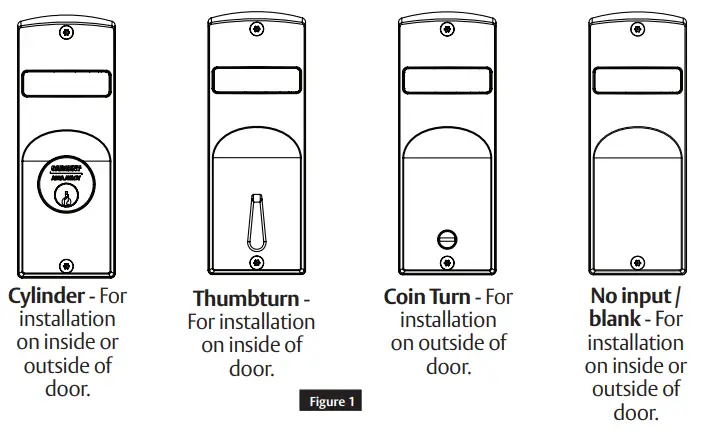
Lock set configuration
To set function of multi-function lock or to re-hand, see instructions on lock body.
Remanding indicator
Indicator spindle cams MUST be oriented correctly per lock function and door mounting location. Verify hand and bevel of door. (Figure 2)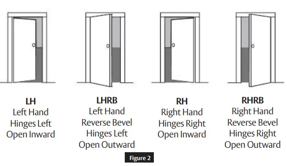

Scan this QR code for the Sargent Indicator Handing Charts
Note:
Stand on outside of locked door when determining door hand.
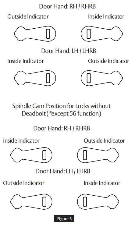
Next, verify inside and/or outside indicators are handed correctly, using Spindle Cam Position chart. (Figure 3) If they are handed correctly, skip to Step 5 “Prepare Door”.
If they are not handed correctly:
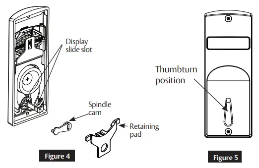
- Remove retaining pad and spindle cam from assembly. (Figure 4)
- Position spindle cam in correct direction for door hand. (Figure 3)
Spindle Cam Position for Locks with Deadbolt (*and 56 function)
Important:
• For thumbturn indicators, make sure thumbturn is positioned in the 12 o’clock direction as shown. (Figure 5) - Slide spindle cam post into correct slot of display slide. (Figure 4)
- Re-seat retaining pad into original position.
- Return indicator to the vacant/unlocked position for installation.
Installation
a Prepare Door for Mortise Lock
Prepare door for function holes, size, and location according to A7050 door marker template, if not already prepped.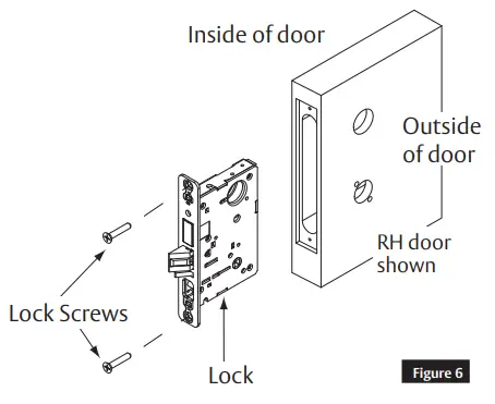
b Install Lock
- Verify strike location according to template. Clean out door pocket and door edge of debris.
- Make sure handing of lock matches handing of door. Slide lock into door. (Figure 6)
- Temporarily hand tighten two (2) lock screws (#12 x 1-1/4″ wood screws, or #12-24 x1/2″ machine screws).
Notes:
• Keep door open until installation is complete.
• If installing lever onto only one (1) side of door (36 function), see separate instruction sheet A7028.
c Prepare Door for Indicator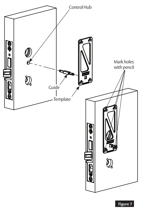
- Insert template guide into control hub on side where indicator will be used. (Figure 7)
- Slide indicator template over template guide.
Important: Make sure the template is properly centered and aligned to ensure smooth indicator operation. - Mark the four (4) hole positions indicated on template.
- Remove guide and template.
- If indicators are being used on both sides of door, repeat steps 1 through 4 for opposite side.
- Remove lock body.
- Drill four (4) marked holes with 3/32″ diameter bit, by 1/2″ deep.
- Reinstall lock body and hand tighten screws.
Note:
If retrofitting over an existing product, ensure door surface is free of chips and debris around holes so indicator will sit flat against door surface.
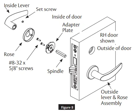
d Install Levers
- Slide outside lever and rose assembly through door and lock body, and hold. (Figure 8)
- Slide inside spindle into lock body hub.
- Slide adapter and plate assembly over spindle.
- Secure with two (2) #8-32 x 5/8″ screws.
- Install inside rose onto adapter plate.
- Install inside lever on adapter plate. Secure with set screw.

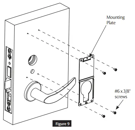
e Install Indicator Mounting Plate
- Screw indicator mounting plate to door with four (4) #6 x 3/8″ sheet metal screws. (Figure 9)
- If indicators are being used on both sides of door, repeat step 1 for opposite side.
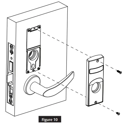
f Install Indicator Assembly
- Verify lock is in unlocked state (turn outside lever to confirm).
- Verify indicator is in vacant/unlocked position.
- Assemble indicator assembly onto mounting plate. (Figure 10)
- Secure indicator assembly to door with two (2) machine screws.
• Use #8-32 x 5/8″ screw for top
• Use #8-32 x 3/8″ screw for bottom - If indicators are being used on both sides of door, repeat steps 1 through 3 for opposite side.
Note:
Torn security screws recommended.
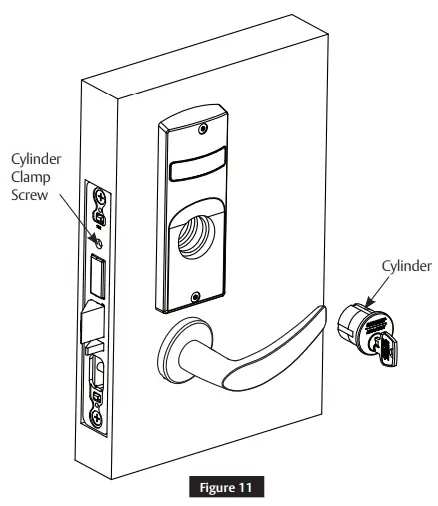
g Install Cylinders
- Thread cylinder into lock until flush with escutcheon surface. (Figure 11)
• Pull key slightly out of cylinder to help thread into lock body. - Tighten cylinder clamp screw with #2 Phillips screwdriver.
• Check operation and adjust if necessary.
 ‘
‘
Notes:
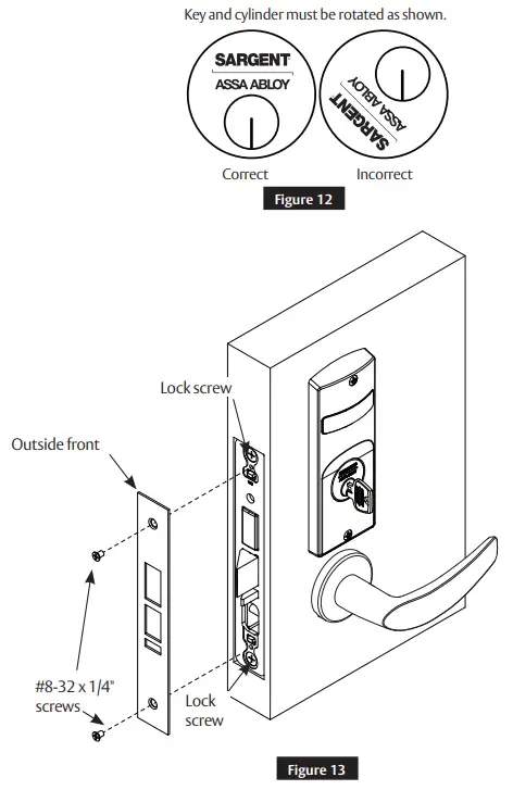
- SARGENT logo must be horizontal and on top. (Figure 12)
- If double cylinder function is used, repeat steps 1 and 2 for second cylinder.
- Removable Core or Interchangeable Core cylinders require a control key (key stamped with C) to remove and install the core. This is not provided standard; it must be requested separately. If requesting 1-bitted control key, specify 113511 cut.
h Install Outside Front
- Tighten the two (2) lock screws completely: (Figure 13)
- Attach outside front with two (2) flat head screws #8-32 x 1/4″.
i Perform Functional Check
DO NOT FORCE if resistance is encountered during functional check. Refer back to Remanding Indicator (if required) section to ensure correct handing. Remand if necessary.
- Insert key into cylinder (if present) and rotate:
• Ensure there is no friction against lock case or any other obstructions. - Check key retracts latch:
• Key should rotate freely. - Throw deadbolt (if present):
• Check key retracts both deadbolt and latch. - Test levers:
• Confirm latch and deadbolt (if installed) retract. - Verify indicator displays correct status when locked and unlocked.
Indicator Parts List
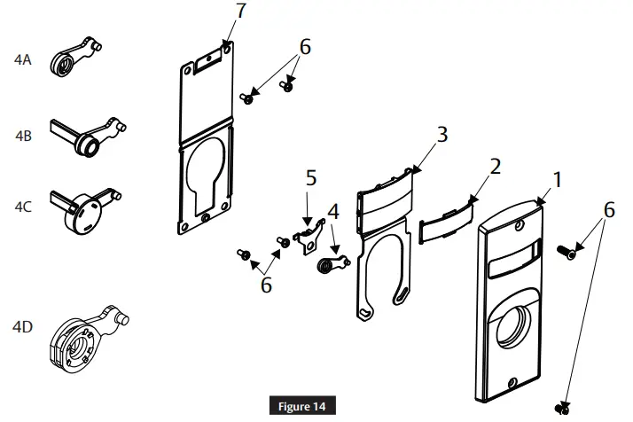
| Figure 14 | Description | Part Number | Req. |
| 1 | Sectional Escutcheon – Cylinder | 81-0742 x finish | 1 |
| Sectional Escutcheon – Coin Turn | 82-5635 x finish | ||
| Sectional Escutcheon – Thumbnut (Standard) | 82-5630 x finish | ||
| Sectional Escutcheon -Thumbnut (LB Option) | 82-5631 x finish | ||
| Sectional Escutcheon – Thumbturn (T1) | 82-5632 x finish | ||
| Sectional Escutcheon -Thumbnut (T2) | 82-5633 x finish | ||
| Sectional Escutcheon – Thumbturn (T3) | 82-5634 x finish | ||
| Sectional Escutcheon – No Input/Blank | 81-0742 x finish | ||
| 2 | Indicator Window | 81-0811 | 1 |
| 3 | Indicator Display Assembly – Green Unlocked / Red Locked | 82-5602 | 1 |
| Indicator Display Assembly – Green Vacant / Red Occupied | 82-5603 | ||
| Indicator Display Assembly – Green Unlocked Icon / Red Locked Icon | 82-5604 | ||
| Indicator Display Assembly – White Unlocked / Red Locked | 82-5605 | ||
| Indicator Display Assembly – White Vacant / Red Occupied | 82-5606 | ||
| Indicator Display Assembly – White Unlocked Icon / Red Locked Icon | 82-5607 | ||
| Indicator Display Assembly – Green Ouverte / Red Fermi | 82-5684 | ||
| Indicator Display Assembly – Green Libre / Red Occupier | 82-5685 | ||
| 4A | Indicator Spindle Cam – Thumbturn/Coin Turn | 81-0745 | 1 |
| 4B | Indicator Spindle Cam – Cylinder/No Input / Blank | 81-0756* | |
| 4C | Indicator Spindle Cam – 05, 37, 38, 59 Function | 82-5577′ | |
| 4D | Indicator Spindle Cam – 05 (Inside) | 82-5673 | 1 |
| 5 | Indicator Retaining Pad | 81-0749 | 1 |
| 6 | Sectional Indicator Screw Pack | 82-5590 x finish | 1 |
| 7 | Sectional Indicator Mounting Plate | 81-0750 | 1 |
| 8 | Sectional Indicator Template Kit (not shown) | 82-5601 | 1 |
* These parts are for 1-3/4″ standard thickness doors. For other thicknesses, please contact factory.
Note:
Reference 8200 Series parts manual for all lock body parts.
![]() WARNING
WARNING
Attention Installer: Improper installation may result in damage to the product and void the factory warranty.
![]() WARNING
WARNING
This product can expose you to lead which is known to the state of California to cause cancer and birth defects or other reproductive harm. For more information go to www.P65warnings.ca.gov.
![]() 1-800-727-5477 • www.sargentlock.com
1-800-727-5477 • www.sargentlock.com
Copyright © 2019, 2020, 2021, 2022, SARGENT Manufacturing Company.
All rights reserved. Reproduction in whole or in part without
the express written permission of SARGENT Manufacturing Company is prohibited.
Patent pending and/or patent www.assaabloydss.com/patents.


