![]() INSTALLATION INSTRUCTIONS
INSTALLATION INSTRUCTIONS
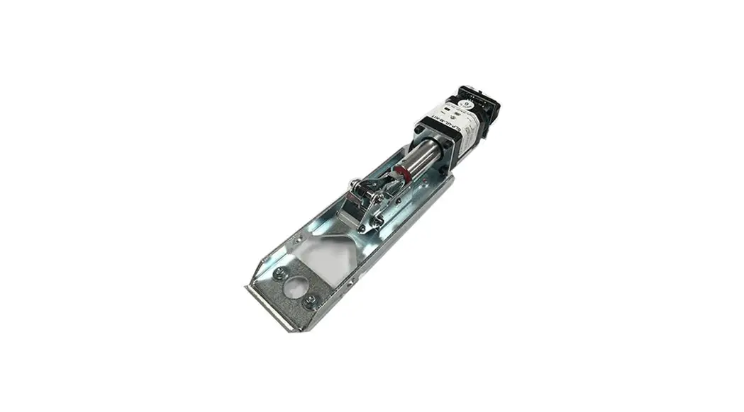
LR100FCK
FIRST CHOICE ELECTRIC LATCH RETRACTION KIT
MODELS: 3600 & 3700
First Choice Electric Latch Retraction Kit
Retrofit Installation Note: 42″ or 48″ exit devices that have been modified to fit a 36″ or smaller opening, may not have the required space to fit the standard E. L. R. assembly. Always verify the distance from the end of the touchpad to the end rail, and if necessary, consult with the factory for appropriate selection.
Remove the push bar. Remove the dogging assembly. Bend Push Bar Spring Box open as shown, to allow Linkage access. Depress the push bar spring box then slide the ELR unit into the device base. Align the second set of two holes over the two base unit holes and attach with the two #10-32 flat head screws supplied. Attach the Linkage with supplied screw as shown. Re-attach the Push Bar.
ELECTRICAL DATA
24VDC @ 1A
RED (+) BLK (-)
PATENT #8,851,530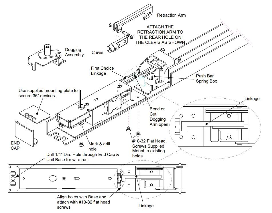
When retrofitting to existing vertical rod devices, adjustment of the rods is required for proper operation of the Electric Latch Retractor. Once the unit is properly installed, energize it so the latch is dogged down, then reconnect the vertical rods to the device and make the proper adjustments.
Any suggestions or comments to this instruction or product are welcome. Please contact us through our website or email [email protected]
USE TEMPLATE WHEN DEVICES ARE LONGER THAN 36″ FOR ADDED STABILITY OF KIT.
ALIGN TEMPLATE TO EXISTING HOLES, FALCON/DOR-O-MATIC or FIRST CHOICE. MARK AND DRILL 1 HOLE FOR 10-32 FLT HD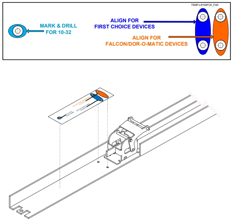
P:\INST INSTRUCTIONS\ELR KITS\INST-LR100FCK_FAK
SECURITY DOOR CONTROLS
WWW.SDCSECURITY.COM
[t] 800.413.8783 805.494.0622
E-mail: [email protected]
801 Avenida Acaso, Camarillo, CA 93012
PO Box 3670, Camarillo, CA 93011


