amber connect ACT400-m Amber Covert
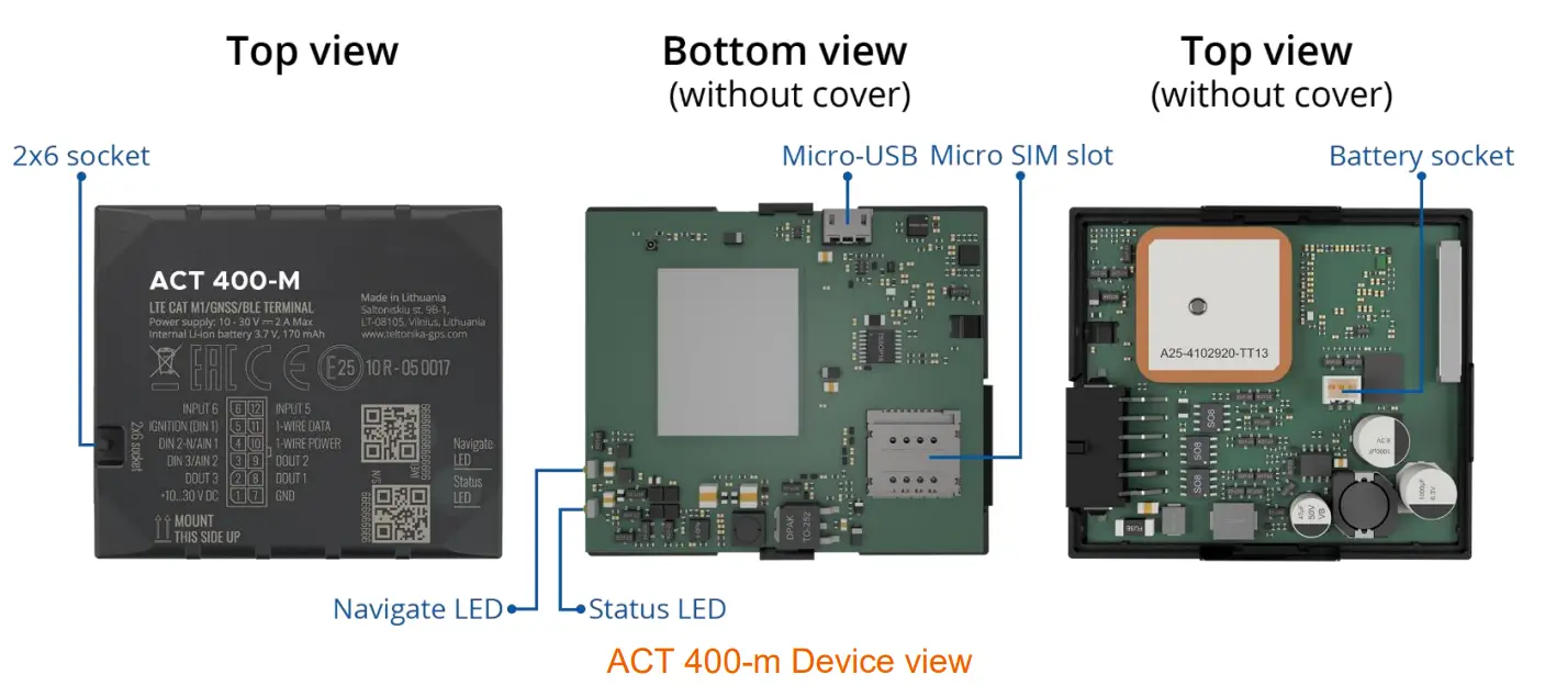
Know your device
Pinout
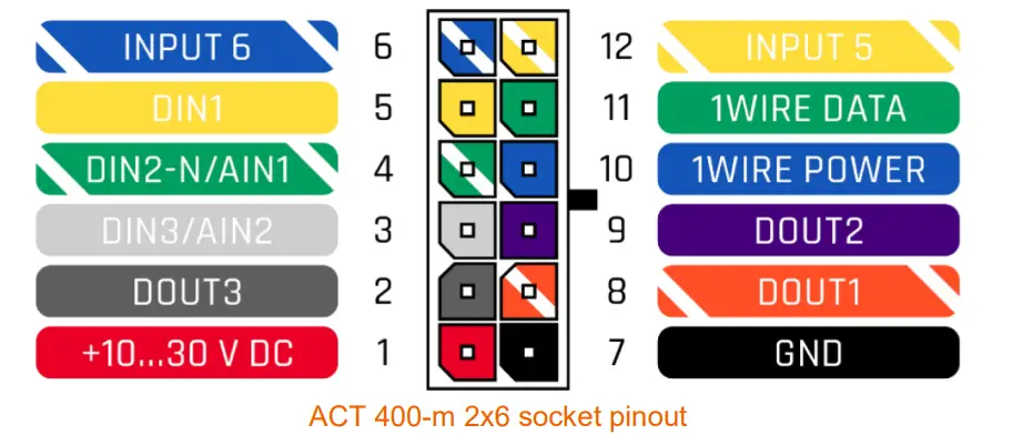
| Pin number | Pin name | Description |
| 1 | VCC (10-30) V DC (+) | Power supply (+10-30 V DC). |
| 2 | DOUT 3 | Digital output, channel 3. Open collector output. Max. 0,5 A DC. |
| 3 | DIN 3 / AIN 2 | Analog input, channel 2. Input range: 0-30 V DC / Digital input, channel 3. |
| 4 | DIN 2-N / AIN 1 | Digital input, channel 2, Negative input (ground sense), Analog input, channel 1, Input range: 0-30 VDC. |
| 5 | DIN 1 | Digital input, channel 1. |
| 6 | INPUT 6 | TX EXT (LVCAN – TX). |
| 7 | GND (-) | Ground pin. (10-30) V DC (―) |
| 8 | DOUT 1 | Digital output, channel 1. Open collector output. Max. 0,5 A DC. |
| 9 | DOUT 2 | Digital output, channel 2. Open collector output. Max. 0,5 A DC. |
| 10 | 1WIRE POWER | +3,8 V output for 1–Wire devices. |
| 11 | 1WIRE DATA | Data for 1–Wire devices. |
| 12 | INPUT 5 | RX EXT (LVCAN – RX). |
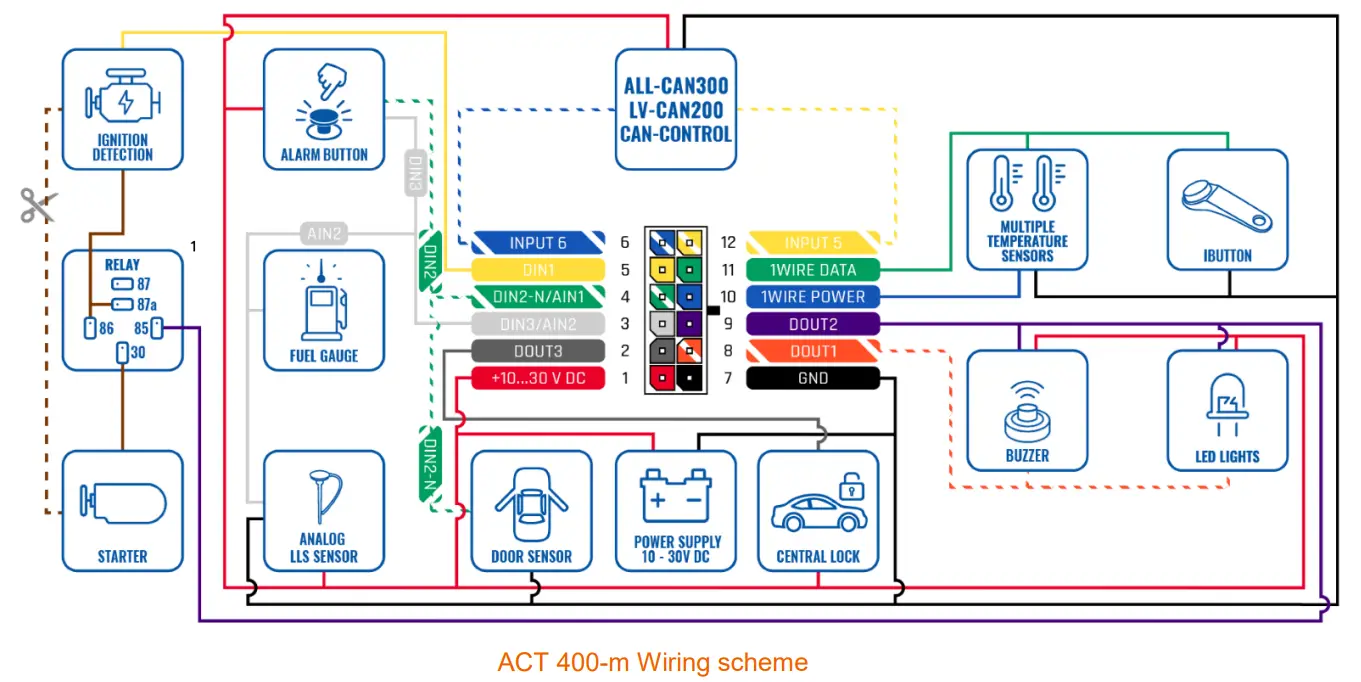
ACT 400-m 2×6 socket pinout
Wiring scheme
Set up your device
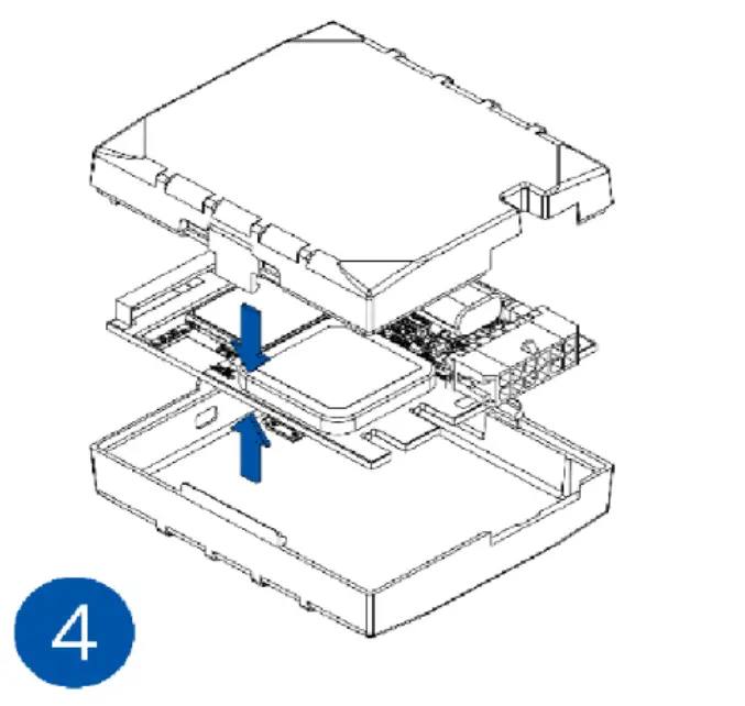
How to insert Micro-SIM card and connect the battery
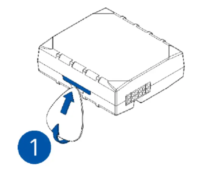
- Cover removal

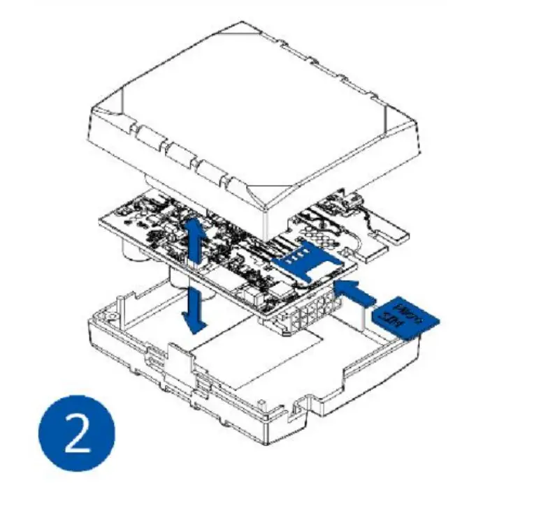
- Micro-SIM card insert

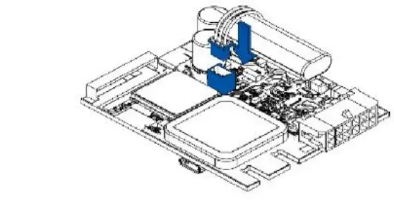
- Battery connection

- Attaching cover back

- Gently remove ACT 400-m cover using plastic pry tool from both sides.
- Insert Micro-SIM card as shown with PIN request disabled or read our Wiki how to enter it later in Amber Configurator. Make sure that Micro-SIM card cut-off corner is pointing forward to slot.
- Connect battery as shown to device. Position the battery in place where it does not obstruct other components.
- After configuration, see “PC Connection (Windows)”, attach device cover back.
Mounting recommendations
Connecting wires
- Wires should be connected while the module is not plugged in.
- Wires should be fastened to stable wires or other non-moving parts. Any heat emitting and/or moving objects should be kept away from the wires.
- There should be no exposed wires. If factory isolation was removed while connecting the wires, the isolation material should be applied.
- If the wires are placed in the exterior or in places where they can be damaged or exposed to heat, humidity, dirt, etc., additional isolation should be applied and the wires should not be loose.
- Wires cannot be connected to the board computers or control units.
Connecting power source
- Be sure that after the car computer goes to sleep mode, power might be still available on the power wires. Depending on the car model, this may happen in 5 to 30 minutes period.
- When the module is connected, measure the voltage again to make sure it did not decrease.
- It is recommended to connect to the main power cable in the fuse box.
- 3 A, 125 V external fuse shall be used.
Connecting ignition wire
- Be sure to check if it is a real ignition wire i. e. power does not disappear after starting the engine.
- Check if this is not an ACC wire (when key is in the first position, most of the vehicle electronics are available).
- Check if power is still available when you turn off any of vehicles devices.
- Ignition is connected to the ignition relay output. As alternative, any other relay, which has power output when ignition is on, may be chosen.
Connecting ground wire
- Ground wire is connected to the vehicle frame or metal parts that are fixed to the frame.
- If the wire is fixed with the bolt, the loop must be connected to the end of the wire.
- For better contact scrub paint from the spot where loop is going to be connected.
LED indications
| Behavior | Meaning |
| Permanently switched on | GNSS signal is not received |
| Blinking every second | Normal mode, GNSS is working |
| Off | GNSS is turned off because: Device is not working or Device is in sleep mode |
| Blinking fast constantly | Device firmware is being flashed |
Status LED indications
| Behavior | Meaning |
| Blinking every second | Normal mode |
| Blinking every two seconds | Sleep mode |
| Blinking fast for a short time | Modem activity |
| Off | Device is not working or Device is in boot mode |
Characteristics
Basic characteristics
| Module | |
| Name | ACT 400-m |
| Technology | LTE CAT M1/NB-IoT/GSM/GPRS/GNSS/BLUETOOTH |
| GNSS | |
| GNSS | GPS, GLONASS, GALILEO, BEIDOU, QZSS, AGPS |
| Receiver | Tracking: 33 |
| Tracking sensitivity | -165 dB |
| Accuracy | < 3 m |
| Hot start | < 1 s |
| Warm start | < 25 s |
| Cold start | < 35 s |
| Cellular | |
| Technology | LTE CAT M1/NB-IoT/GSM |
| 2G bands | BG95: B2/B3/B5/B8 BG96: B2/B3/B5/B8 |
| 4G bands | BG95: LTE-FDD (CAT M1): B1/B2/B3/B4/B5/B8/B12/B13/B18/B19/B20/B25/B26/B27/ B28/B66/B85 LTE-FDD (CAT NB2): B1/B2/B3/B4/B5/B8/B12/B13/B18/B19/B20/B25/B28/B66/ B71/B85 GSM: 850/900/1800/1900 BG96: LTE FDD: B1/B2/B3/B4/B5/B8/B12/B13/B18/B19/B20/B28 LTE TDD: B39 (for CAT M1 only) |
| Data transfer | BG95: LTE: Max. 588Kbps (DL)/Max.1119Kbps (UL) GPRS: Max. 107Kbps (DL)/Max. 85.6Kbps (UL) BG96: LTE: Max. 375Kbps (DL)/Max.375Kbps (UL) GPRS: Max. 107Kbps (DL)/Max. 85.6Kbps (UL) |
| Transmit power | Class 4 for GSM850/900: 23±2dBm Class 1 for GSM1800/1900: 20±2dBm Class 3 for LTE-TDD: 23±2.7dBm Class 3 for LTE-FDD: 23±2.7dBm |
| Data support | SMS (text/data) |
| Power | ||
| Input voltage range | 10-30 V DC with overvoltage protection | |
| Back-up battery | 170 mAh Li-Ion battery 3.7 V (0.63 Wh) | |
| Internal fuse | 3 A, 125 V | |
| Power consumption | At 12V < 3 mA (Ultra Deep Sleep) At 12V < 5 mA (Deep Sleep) At 12V < 11 mA (Online Deep Sleep) | |
| At 12V < 18 mA (GPS Sleep) At 12V < 34 mA (nominal with no load) At 12V < 2A Max. (with full Load / Peak) | ||
| Bluetooth | ||
| Specification | 4.0 + LE | |
| Supported peripherals | Temperature and Humidity sensor, Headset, OBDII dongle, Inateck Barcode Scanner, Universal BLE sensors support | |
| Interface | ||
| Digital Inputs | 3 | |
| Negative Inputs | 1 (Digital input 2) | |
| Digital Outputs | 3 | |
| Analog Inputs | 2 | |
| CAN interfaces | 1 | |
| 1-Wire | 1 | |
| GNSS antenna | Internal High Gain | |
| GSM antenna | Internal High Gain | |
| USB | 2.0 Micro-USB | |
| LED indication | 2 status LED lights | |
| SIM | Micro-SIM + eSIM | |
| Memory | 128MB internal flash memory | |
| Physical specification | ||
| Dimensions | 65 x 56 x 20,6 mm (L x W x H) | |
| Weight | 55 g | |
| Operating environment | |
| Operating temperature (without battery) | -20 °C to +85 °C |
| Storage temperature (without battery) | -20 °C to +85 °C |
| Operating temperature (with battery) | -20 °C to +40 °C |
| Storage temperature (with battery) | -20 °C to +45 °C |
| Operating humidity | 5% to 95% non-condensing |
| Ingress Protection Rating | IP41 |
| Battery charge temperature | 0 °C to +45 °C |
| Battery discharge temperature | -20 °C to +60 °C |
| Features | |
| Sensors | Accelerometer |
| Scenarios | Green Driving, Over Speeding detection, Jamming detection, GNSS Fuel Counter, DOUT Control Via Call, Excessive Idling detection, Immobilizer, i Button Read Notification, Unplug detection, Towing detection, Crash detection, Auto Geofence, Manual Geofence, Trip, Ground Sense |
| Sleep modes | GPS Sleep, Online Deep Sleep, Deep Sleep, Ultra Deep Sleep |
| Configuration and firmware update | FOTA Web, FOTA, Amber Configurator (USB, Bluetooth), FMBT mobile application (Configuration) |
| SMS | Configuration, Events, DOUT control, Debug |
| GPRS commands | Configuration, DOUT control, Debug |
| Time Synchronization | GPS, NITZ, NTP |
| Fuel monitoring | LLS (Analog), LV-CAN200, ALL-CAN300, CAN- CONTROL, CAN-CONTROL, OBDII dongle |
| Ignition detection | Digital Input 1, Accelerometer, External Power Voltage, Engine RPM (CAN Adapters, OBDII dongle) |
Electrical characteristics
| Characteristic description | Value | |||
| Min. | Typ. | Max. | Unit | |
| Supply Voltage | ||||
| Supply Voltage (Recommended Operating Conditions) | +10 | +30 | V | |
| Digital Output (Open Drain grade) | ||||
| Drain current (Digital Output OFF) | 120 | μA | ||
| Drain current (Digital Output ON, Recommended Operating Conditions) | 0.1 | 0.5 | A | |
| Static Drain-Source resistance (Digital Output ON) | 400 | 600 | mΩ | |
| Digital Input | ||||
| Input resistance (DIN1) | 47 | kΩ | ||
| Input resistance (DIN2) | 38.45 | kΩ | ||
| Input resistance (DIN3) | 150 | kΩ | ||
| Input voltage (Recommended Operating Conditions) | 0 | Supply voltage | V | |
| Input Voltage threshold (DIN1) | 7.5 | V | ||
| Input Voltage threshold (DIN2) | 2.5 | V | ||
| Input Voltage threshold (DIN3) | 2.5 | V | ||
| Power | ||
| Input voltage range | 10-30 V DC with overvoltage protection | |
| Back-up battery | 170 mAh Li-Ion battery 3.7 V (0.63 Wh) | |
| Internal fuse | 3 A, 125 V | |
| Power consumption | At 12V < 3 mA (Ultra Deep Sleep) At 12V < 5 mA (Deep Sleep) At 12V < 11 mA (Online Deep Sleep) | |
| At 12V < 18 mA (GPS Sleep) At 12V < 34 mA (nominal with no load) At 12V < 2A Max. (with full Load / Peak) | ||
| Bluetooth | ||
| Specification | 4.0 + LE | |
| Supported peripherals | Temperature and Humidity sensor, Headset, OBDII dongle, Inateck Barcode Scanner, Universal BLE sensors support | |
| Interface | ||
| Digital Inputs | 3 | |
| Negative Inputs | 1 (Digital input 2) | |
| Digital Outputs | 3 | |
| Analog Inputs | 2 | |
| CAN interfaces | 1 | |
| 1-Wire | 1 | |
| GNSS antenna | Internal High Gain | |
| GSM antenna | Internal High Gain | |
| USB | 2.0 Micro-USB | |
| LED indication | 2 status LED lights | |
| SIM | Micro-SIM + eSIM | |
| Memory | 128MB internal flash memory | |
| Physical specification | ||
| Dimensions | 65 x 56 x 20,6 mm (L x W x H) | |
| Weight | 55 g | |
| Output current (Uout > 3.0 V) | 30 | mA | ||
| Short circuit current (Uout = 0) | 75 | mA |
| NEGATIVE INPUT | ||||
| Input resistance | 38.45 | kΩ | ||
| Input voltage (Recommended Operating Conditions) | 0 | Supply voltage | V | |
| Input voltage threshold | 0.5 | V | ||
| Sink current | 180 | nA | ||
Safety information
This message contains information on how to operate ACT 400-m safely. By following these requirements and recommendations, you will avoid dangerous situations. You must read these instructions carefully and follow them strictly before operating the device!
- The device uses SELV limited power source. The nominal voltage is +12 V DC. The allowed voltage range is +10…+30 V DC.
- To avoid mechanical damage, it is advised to transport the device in an impact-proof package. Before usage, the device should be placed so that its LED indicators are visible. They show the status of device operation.
- When connecting the 2×6 connector wires to the vehicle, the appropriate jumpers of the vehicle power supply should be disconnected.
- Before unmounting the device from the vehicle, the 2×6 connector must be disconnected. The device is designed to be mounted in a zone of limited access, which is inaccessible to the operator. All related devices must meet the requirements of EN 60950-1 standard. The device ACT 400-m is not designed as a navigational device for boats.
 | Do not disassemble the device. If the device is damaged, the power supply cables are not isolated or the isolation is damaged, DO NOT touch the device before unplugging the power supply. |
| All wireless data transferring devices produce interference that may affect other devices which are placed nearby. |
 | The device must be connected only by qualified personnel. |
 | The device must be firmly fastened in a predefined location. |
| The programming must be performed using a PC with autonomic power supply. |
| Installation and/or handling during a lightning storm is prohibited. |
 | The device is susceptible to water and humidity. |
 | Risk of explosion if battery is replaced by an incorrect type. Dispose of used batteries according to the instructions. |
| Battery should not be disposed of with general household waste. Bring damaged or worn-out batteries to your local recycling center or dispose them to battery recycle bin found in stores. |
Certification and Approvals
- ACT 400-m EAC
- ACT 400-m REACH
- ACT 400-m Declaration of IMEI assignment
- ACT 400-m CE / RED
- ACT 400-m E-Mark
- ACT 400-m RoHS
- ACT 400-m Declaration of device operation temperature
 This sign on the package means that it is necessary to read the User‘s Manual before your start using the device. Full User‘s Manual version can be found in our Wiki.
 This sign on the package means that all used electronic and electric equipment should not be mixed with general household waste.
 Hereby, Amber declare under our sole responsibility that the above described product is in conformity with the relevant Community harmonization: European Directive 2014/53/EU (RED).
Warranty
Amber guarantees its products to be free of any manufacturing defects for a period of 24 months. With additional agreement we can agree on a different warranty period, for more detailed information please contact our sales manager.
All batteries carry a reduced 6 month warranty period. If a product should fail within this specific warranty time, the product can be
- Repaired
- Replaced with a new product
- Replaced with an equivalent repaired product fulfilling the same functionality
- Amber can also repair products that are out of warranty at an agreed cost.
Warranty Disclaimer
Amber products are intended to be used by persons with training and experience. Any other use renders the limited warranties expressed herein and all implied warranties null and void and same are hereby excluded. also excluded from this limited warranty are any and all incidental or consequential damages including but not limited to, loss of use or revenue, loss of time, inconvenience or any other economic loss.
CUSTOMRT SUPPORT
Need help? Contact 24/7 live support!

![]() ln AppChat
ln AppChat
![]() Chatvio website www.amberconnect.com
Chatvio website www.amberconnect.com
Works with Android phones and tablets, iPhone, iPad. Compatible with Chrome, Mac and PC web browsers.
 |  |
 | |
| Scan this QR code to download your App | |
Amber Connect

© 2022 Amber Connect limited. All rights reserved