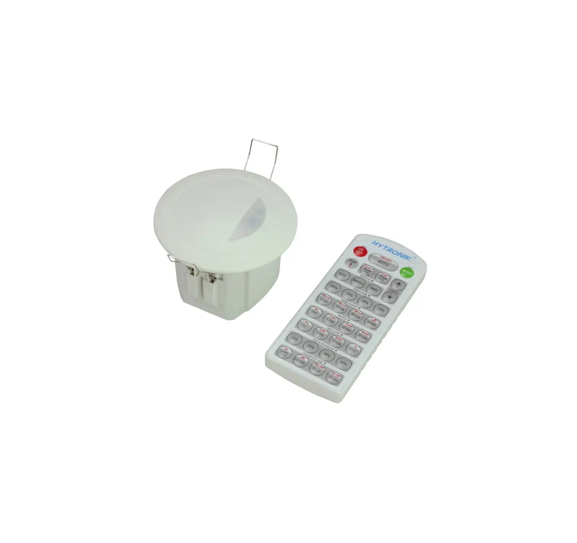
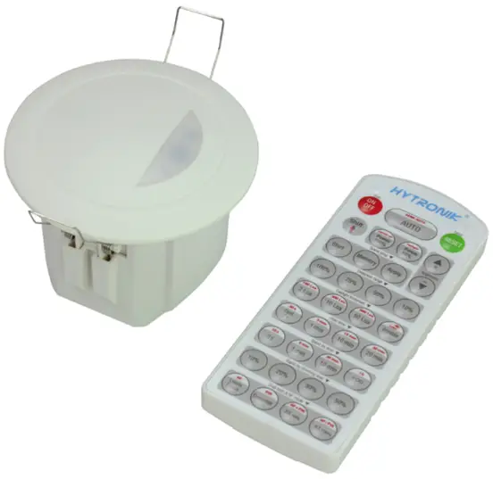
HYTRONIK HMW23 Flush Mount Microwave Dali Sensor
Technical Specifications
| Product type | Tri-level control microwave DALI sensor |
| Operating voltage | 9.5 ~ 22.5VDC ( suitable DALI power supply) |
| Input current | Approx.12mA |
| Power consumption | < 0.5W |
| Detection angle | 360o |
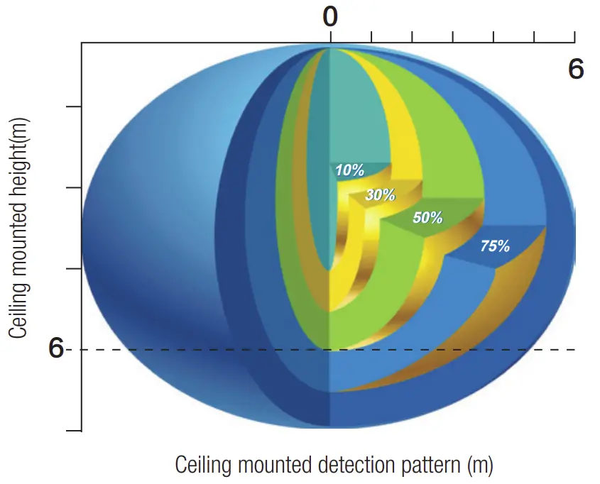
| Detection area (Max.)* | Installation Height : 6m Detection Range (Ø) :12m |
| Detection range | 10% / 50% / 75% / 100% |
| Hold time | 2s / 30s / 1min / 5min / 10min / 15min / 20min / 30min |
| Stand-by time | 0s / 10s / 1min / 5min / 10min / 30min / 1h / +∞ |
| Stand-by dimming level | 10% / 20% / 30% / 50% |
| Daylight threshold | 2Lux / 10Lux / 50Lux / Disable |
| Warmming-up time | 20s |
| Operating temperature | -20oC ~ +50oC |
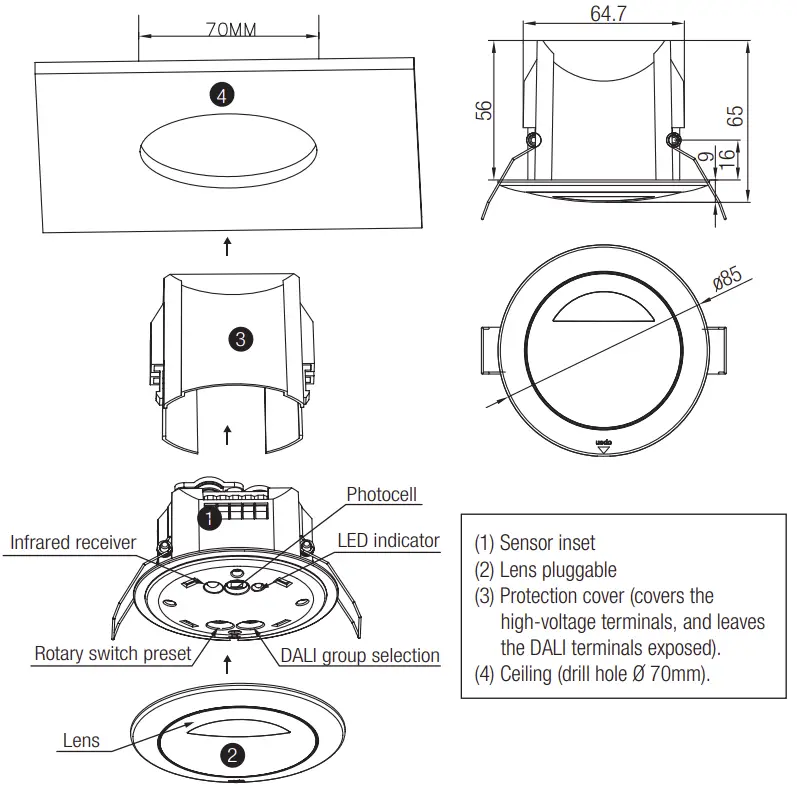
Installation
![]() Warnings
Warnings
- Installation of the sensor involves connecting it to the mains supply. This work must be carried out by a specialist in accordance with electrotechnical regulations.
- Disconnect supply before installing.

Note: We recommend the mounting distance between sensor to sensor should be more than 2m to prevent sensors from false-triggering
Rotary Switch Settings
A rotary switch is built inside the sensor for scene selection / fast programming. Total 16 channels available: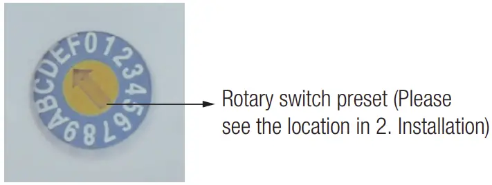
Channel | Detection range | Hold time | Stand-by time | Stand-by dimming level | Daylight threshold |
| 0 | 100% | 5s | 10s | 10% | Disable |
1 | 100% | 1min | 5min | 10% | 2Lux |
| 2 | 100% | 5min | 10min | 10% | 10Lux |
3 | 100% | 5min | 30min | 10% | 30Lux |
| 4 | 100% | 5min | 0s | Disable | 10Lux |
5 | 100% | 5min | +∞ | 10% | 30Lux |
| 6 | 100% | 5min | +∞ | 30% | Disable |
7 | 100% | 10min | 10min | 10% | 2Lux |
| 8 | 100% | 10min | 30min | 10% | 10Lux |
9 | 100% | 10min | +∞ | 10% | 30Lux |
| A | 100% | 10min | +∞ | 30% | Disable |
B | 75% | 10min | +∞ | 10% | 30Lux |
| C | 50% | 10min | +∞ | 10% | 10Lux |
D | 100% | 30min | +∞ | 10% | 50Lux |
| E | 100% | 30min | +∞ | 30% | Disable |
F | 100% | 5s | 10s | 10% | 2Lux |
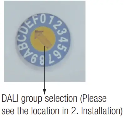
DALI group selection
DALI group configuration can be done on PC or on the rotary switch:
- There are 16 channels available on the rotary switch. “0” is for DALI broadcast, the rest 15 channels is for end user to define the application unit.
- PC grouping can overwrite rotary switch grouping, the last setting controls.
- The rotary switch channel is corresponding to the groups listed below

Switch channel | DALI group | Switch channel | DALI group |
| 0 | broadcast | 8 | group 7 |
1 | group 0 | 9 | group 8 |
| 2 | group 1 | A | group 9 |
3 | group 2 | B | group 10 |
| 4 | group 3 | C | group 11 |
5 | group 4 | D | group 12 |
| 6 | group 5 | E | group 13 |
7 | group 6 | F | group 14 |
Functions
This DALI sensor is designed for incorporated in the DALI system, taking command from the DALI master, accepting and carrying out the grouping work with up to 64 luminaires. It can switch on/off, or dim the assigned group members and feed back the status to the DALI master.
Tri-level Control (Corridor Function)
Hydronic builds this function inside the motion sensor to achieve tri-level control, for some areas require a light change notice before switch-off.
It offers 3 levels of light: 100%–>dimmed light–>off; and 2 periods of selectable waiting time: motion hold-time and stand-by period; Selectable daylight threshold and freedom of detection area.
Synchronization Function
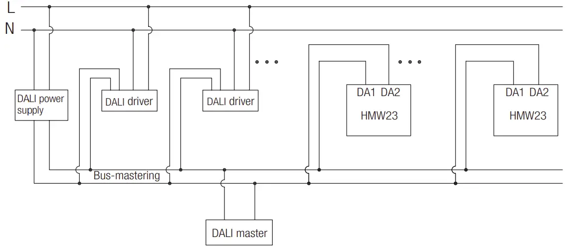
By connecting the DALI terminals in parallel (see wiring diagram), no matter which sensor detects motion, all HMW23 in the group will turn on the lights when surrounding natural light is below the daylight threshold. The sensor antenna is shared and the detection area could be widely enlarged in this way.
Wiring Diagram
Detection Pattern
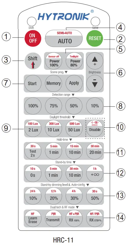
Permanent ON/OFF ① ]
Press button ① , to select permanent ON or permanent OFF mode.
* Press button ② / ③ to resume automatic operation.
The mode will change to AUTO Mode after power failure.
RESET[ button ② ]
Press button ② , all settings go back to the rotary switch settings.
Shift [ button ③ ]
Press button ③ , the LED on the top left corner is on for indication.
All values / settings in RED are in valid for 20 seconds.
Auto Mode [ button ④ ]
Press button ④ to initiate automatic mode.
The sensor starts working and all settings remain as before the light was switched ON/OFF.
Note: the function of Semi-auto is disabled.
Power output [ button ⑤ ]
All buttons in zone ⑤ are disabled.
Brightness +/- [ button ⑥ ]
All buttons in zone ⑥ are disabled
Scene prog. [ zone ⑦ ] (One-key-commissioning)
- Press button “Start” to program.
- Select the buttons in ⑧ “Detection range”, ⑨ / ⑩ “Daylight threshold”, ⑪ “Hold time”, ⑫ “Stand-by time”, ⑬ “Stand-by dimming level” to set all parameters.
- Press button “Memory” to save all the settings programmed in the remote control.
- Press button “Apply” to set the settings to each sensor unit(s).
For example, to pre-set detection range 100%, daylight threshold Disable, hold time 5min, stand-by time +∞, stand-by dimming level 30%, steps should be:
Press button ⑦ Start, button ⑧ 100%, ⑩ Disable, ③ Shift, ⑪ 5min, ③ Shift, ⑫ +∞, ⑬ 30%, ⑦ Memory. By pointing to the sensor unit(s) and pressing ⑦ Apply, all settings are passed on the sensor(s).
Detection range [ zone ⑧ ]
Press buttons in zone ⑧ to set detection range at 100% / 75% / 50% / 10%.
Daylight threshold [ zone ⑨ ]
Press buttons in zone ⑨ to set the daylight sensor at 2Lux / 10Lux / 50Lux or Disable.
Ambient daylight threshold [ button ⑩ ]
- Press button ③ Shift, the red LED is on for indication.
- Press button ⑩ , the ambient lux level is sampled and set as the new daylight threshold.
Hold time [ zone ⑪ ]
Press buttons in zone ⑪ to set the hold time at 2s / 30s / 1min / 5min / 10min / 15min / 20min / 30min.
Note:
- To set hold-time at 30s / 5min / 15min / 30min, press button ③ Shift at first.
- 2s is for test purpose only, stand-by period and daylight sensor settings are disabled in this mode.
*To exit from Test mode, press button ② or any button in zone ⑪ .
Stand-by time [ zone ⑫ ]
Press buttons in zone ⑫ to set the stand-by period at 0s / 10s / 1min / 5min / 10min / 30min / 1h / +∞.
Note: “0s” means on/off control; “+∞” means bi-level control, 100% on when motion detected, and remains at the stand-by dimming level when no presence after hold-time.
Stand-by dimming level [ zone ⑬ ]
Press buttons in zone ⑬ to set the stand-by dimming level at 10% / 20% / 30% / 50%.
Note: the function of 24h/12h/4h/30s are disabled.
Dual tech & RF mode [ zone ⑭ ]
All buttons in zone ⑭ are disabled.
Trouble Shooting
| MALFUNCTION CAUSE REMEDY | CAUSE | REMEDY |
| The fixture does not light up | Incorrect daylight threshold setting | Adjust daylight threshold setting |
| Faulty fixture | Replace fixture | |
| No power supply | Check power to sensor | |
| Detection zone not targeted | Check detection area setting | |
| The fixture is always on | Continued movement in the detection zone | Check detection area setting |
| The fixture is on when it should not | Sudden change in temperature due to weather (wind, rain, snow) or air expelled from fans, open windows | Adjust zone, change installation site |
Hydronic Industrial Ltd. | www.hytronik.com
3rd Floor, block C, complex building, 155#, Baingan road south,
Baingan village, Xiao Jinn Kou town, Hunching district, Huizhou 516023
Tel: 86-752-2772020 Fax: 86-752-2777877