
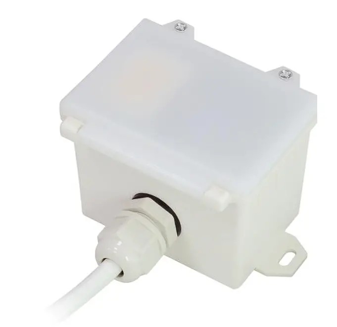
HYTRONIK HMW35 High Bay Microwave Dali Sensor
Technical Specifications
- Product type High bay microwave DALI sensor (tri-level control)
- Operating voltage 220~240VAC 50/60Hz
- Switched power Maximum 20pcs DALI devices, Maximum 40mA
- Power consumption < 0.5W
- Detection angle 360o
- Detection area (Max.)*
- Detection range 10% / 50% / 75% / 100%
- Hold time 2s / 30s / 1min / 5min / 10min / 15min / 20min / 30min
- Stand-by time 0s / 10s / 1min / 5min / 10min / 30min / 1h / +
- Stand-by dimming level 10% / 20% / 30% / 50%
- Daylight threshold 2 ~ 500Lux, Disable
- Warming up time 20s
- Operating temperature -20oC ~
Installation
Warnings:
- Installation of the sensor involves connecting it to the mains supply. This work must be carried out by a specialist in accordance with electrotechnical regulations.
- Disconnect supply before installing.
Ceiling mount
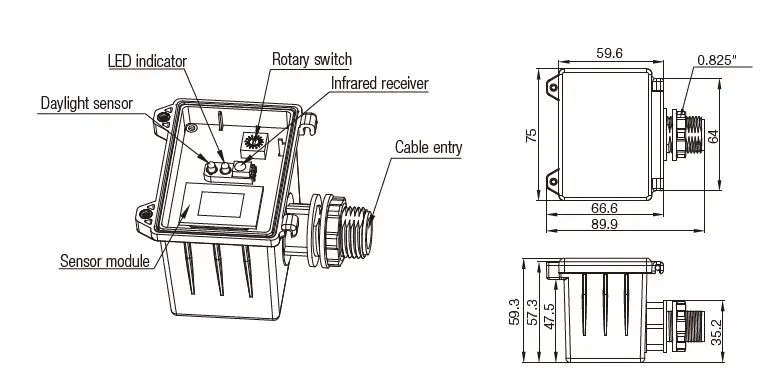
Screw to the Luminaire by conduit
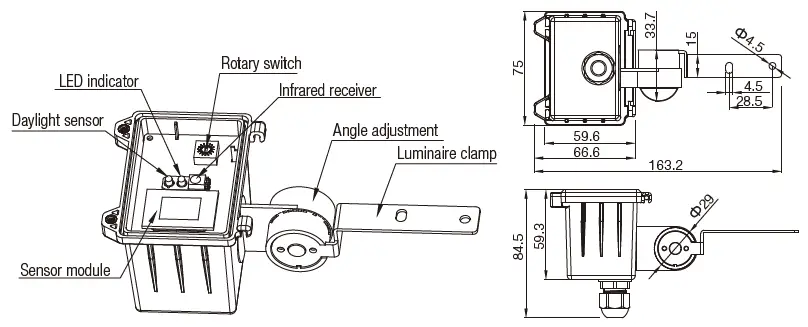
Attach to the shade by clamp
Note: We recommend the mounting distance between sensor to sensor should be more than 2m to prevent sensors from false-triggering.
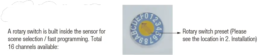
Rotary Switch Settings
| Channel | Detection range | Hold time | Stand-by time | Stand-by dimming level | Daylight threshold |
| 0 | 100% | 5s | 10s | 10% | Disable |
| 1 | 100% | 1min | 5min | 10% | 2Lux |
| 2 | 100% | 5min | 10min | 10% | 10Lux |
| 3 | 100% | 5min | 30min | 10% | 30Lux |
| 4 | 100% | 5min | 0s | Disable | 10Lux |
| 5 | 100% | 5min | +∞ | 10% | 30Lux |
| 6 | 100% | 5min | +∞ | 30% | Disable |
| 7 | 100% | 10min | 10min | 10% | 2Lux |
| 8 | 100% | 10min | 30min | 10% | 10Lux |
| 9 | 100% | 10min | +∞ | 10% | 30Lux |
| A | 100% | 10min | +∞ | 30% | Disable |
| B | 75% | 10min | +∞ | 10% | 30Lux |
| C | 50% | 10min | +∞ | 10% | 10Lux |
| D | 100% | 30min | +∞ | 10% | 50Lux |
| E | 100% | 30min | +∞ | 30% | Disable |
| F | 100% | 5s | 10s | 10% | 2Lux |
Functions
Tri-level Control (Corridor Function)
Hytronik builds this function inside the motion sensor to achieve tri-level control, for some areas require a light change notice before switch-off.
It offers 3 levels of light: 100%–>dimmed light–>off; and 2 periods of selectable waiting time: motion hold-time and stand-by period; Selectable daylight threshold and freedom of detection area.
Lux Off Function
The built-in daylight sensor can read ambient natural light and switch off the fixture automatically whenever artificial light is unneeded (natural light lux level exceeds daylight threshold).
Note: if the stand-by time is preset at “+∞”, the fixture never switches off even when natural light is sufficient.
Load Indication
The light will flash ONCE rapidly after receiving the command from the remote controller. Note: There is no load indication (the light will not flash) when button ON/OFF, POWER 100% or POWER 80% is pressed.
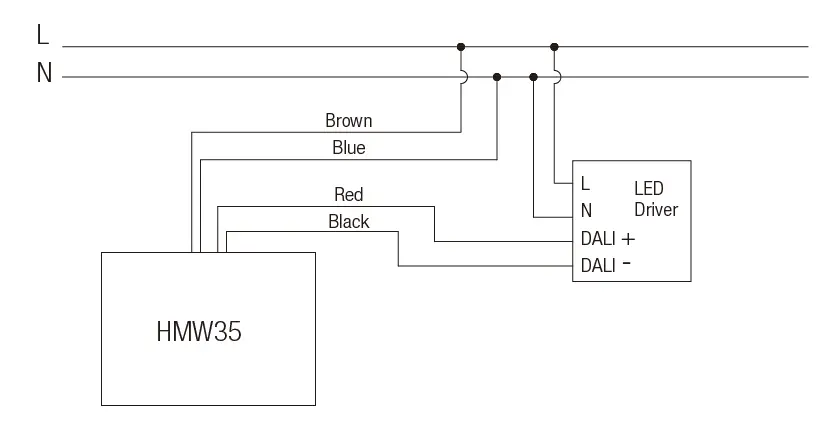
Wiring Diagram
Detection Pattern
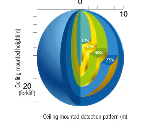
* For single person walking across, the detection range is reduced by 1/3
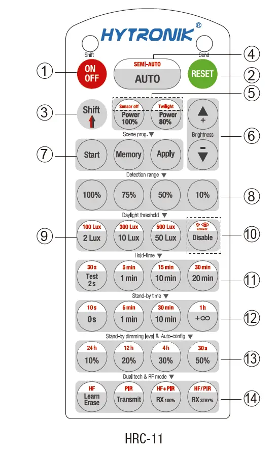
Permanent ON/OFF [ ]
Press button ,to select permanent ON or permanent OFF mode.
* Press button / to resume automatic operation.
The mode will change to AUTO Mode after power failure.
RESET
button Press button, all settings go back to the rotary Switch settings.
Shift[ button]
Press button, the LED on the top left cormer is on for indication. All values/ settings in RED are in valid for 20 seconds.
Auto Mode [ button Press]
button@to initiate automatic mode. The sensor starts working and all settings remain as before the light was switched ON/OFF. Note: the function of Semi-auto is disabled.
Power output [ button61]
Press button, the light output shifts between 80% and 100%. Note: the function of “Sensor off” and “Twilight” are disabled.
Brightness +/- [ button ]
Press button@to adjust the light brightness between 10%-100%.
Scene prog. [ zone 1 (One-key-commissioning)
- Press button “start” to program.
- Select the buttons in @ “Detection range”, O/® “Daylight thresholo OHold time”, “Stand-by time”, “Stand-by dimming level to set all parameters.
- Press button “Memory” to save al the settings programmed in the remote control. 4. Press button “Apply” to set the settings to each sensor unit(s). For example, to pre-set detection range 100%, daylight threshold Disable, hold time 5min, stand-by time +oo, stand-by dimming level 30%, steps should be: Press buttonD Start, button100%, O Disable, 3 Shift, 95min,
Detection range [ zone ®]
Press buttons in zone to set detection range at 100%/ 75%%/ 50%/10%.
Daylight threshold [ zone ]
Press buttons in zone to set the daylight sensor at 2Lux / 10Lux / 50Lux/ 100Lux/ 300Lux/ 500Lux or Disable. Note: To set daylight sensor at 100LUx/ 300 Lux / 500Lux, press button Shift at first.
Ambient daylight threshold [ button®]
- Press button Shift, the red LED is on for indication.
- Press button@, the ambient lux level is sampled and set as the new daylight threshold.
Hold time [ zone D]
Press buttons in zone to set the hold time at 2s/30s/1min/ 5min/10min /15min / 20min /30min. Note: 1.To set hold-time at 30s /5min/ 15min /30min, press button Shift at first. 2. 2s is for test purpose only, stand-by period and daylight sensor settings are disabled in this mode. To exit from Test mode, press buttonor any button in zone O.
Stand-by time [ zone ]
Press buttons in zone to set the stand-by period at Os/ 10s/ 1min /5min/10min /30min / 1h/+o Note: “0s” means on/off control; “+oo” means bi-level control, 100% on when motion detected, and remains at the stand-by dimming level when no presence after hold-time.
Stand-by dimming level [ zone ]
Press buttons in zone 3to set the stand-by dimming level at 10% 20% /30%/ 50%. Note.the function of 24h/ 12h/ 4h/ 30s are disabled.
Dual tech & RF mode [ zone 9]
All buttons in zone are disabled.
Trouble Shooting
| MALFUNCTION CAUSE REMEDY | CAUSE | REMEDY |
| The fixture does not light up | Incorrect daylight threshold setting | Adjust daylight threshold setting |
| Faulty fixture | Replace fixture | |
| No power supply | Check power to sensor | |
| Detection zone not targeted | Check detection area setting | |
| The fixture is always on | Continued movement in the detection zone | Check detection area setting |
| The fixture is on when it should not | Sudden change in temperature due to weather (wind, rain, snow) or air expelled from fans, open windows | Adjust zone, change installation site |


