
![]() K-BUS-4G-TIT Titania Panel
K-BUS-4G-TIT Titania Panel
Installation Guide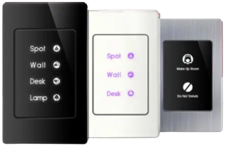
INSTALLATION MANUAL
TIS TITAN / TITANIA PANEL
2/3G Touch Switch
Model: TIT-2G-BUS-K, TIT-3G-BUS-K, TIT-4G-BUS-K TIT-2G-BUS-S, TIT-3G-BUS-S, TIT-4G-BUS-S
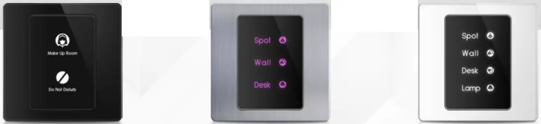
 PRODUCT INFORMATION
This product is a wall switch with touch buttons designed for lights and motorized curtains control. It offers customizable backlit color and frame covers for an easy combination with interior schemes.
PRODUCT SPECIFICATIONS
| Touch | Active area Touch type | 2-3 buttons Capacitive | |
| Input | Temp sensor Dry inputs | Resistive temp sensor 2 Digital inputs | |
| Output | Model 2G Model 3G Model 4G | 2 Relay outputs 5A 3 Relay outputs 5A 4 Relay outputs 3A | |
| TIS Bus“ | Number of devices on 1 line Bus voltage Current consumption | Max. 64 12-32 V DC <60 mA / 24 V DC | |
| Protection | Reverse polarity protection ESD protection | ||
| Reaction time | approx. 20ms | ||
| Mounting | Wall mount | with 2 screws on the back box (UK, US) | |
| Connection terminal | Data & digital inputs Relay channels | 6 pushing pin type 1.5mm 4 pushing pin type 2.5 mm | |
| Operation | Touch buttons Backlight TIS bus Upgrading | 2-3 touch buttons for control 2-3 RGB indicators TIS protocol messages & commands Rs485 upgrade kit | |
| Functions | 1 Press Long Press Double click | ON/OFF/Scene Adjust lights brightness Extra scene | |
| Dimensions (Width × Length × Height) | Titan with the cover Titania with the cover | 29mm × 90mm × 86mm 29mm × 66mm × 110mm | |
| Housing | Materials Casing color Internal Parts color IP rating | Fireproof PC / Glass in front Aluminum, glass, or plastic frame Black IP 50 |
![]()
![]() Read Instructions
Read Instructions
We recommend that you read this
Instruction Manual before installation.![]() Safety instructions
Safety instructions
Electrical equipment should only be installed and fitted by electrically skilled persons.
Failure to follow the instructions may cause damage to the device and other hazards.
These instructions are an integral part of the product and must remain with the end customer.![]() Programming
Programming
This device can be tested and programmed manually. Advanced programming requires knowledge of the TIS Device Search software and instruction in the TIS advanced training courses.![]() Simple Installation
Simple Installation
Using 2 drywall screws, simply screw this panel to the wall.
The Titan & Titania panels fit into the UK & US junction boxes respectively.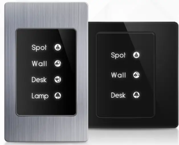
![]() Mounting Location
Mounting Location
Install in a dry, indoor area with a suitable temperature and humidity range.![]() Data Cable
Data Cable
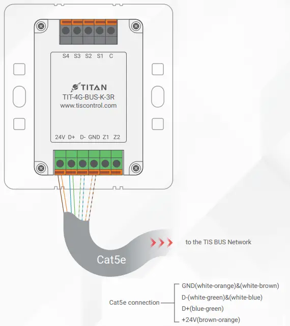
Use screened stranded RS485 data cable with four twisted pairs. Configure devices in a “Daisy Chain.”
Do not cut or terminate live data cables.![]() Electrical Wires
Electrical Wires
The recommended wire size for light channels is 1.5mm – 2.5mm. The installer should consider the total current consumption when selecting the wires.![]() Warranty
Warranty
There is a two-year warranty provided by law. The hologram warranty seal and product serial number are available on each device.
 INSTALLATION STEPS
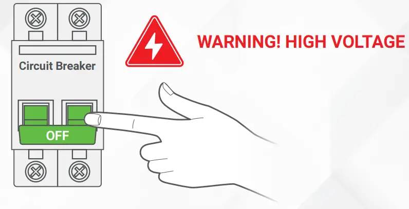
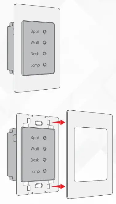
- Turn off the power source.

- Separate the plastic wall cover from the panel

- Insert the wires into the panel. Connect the TIS- bus connection to 24V+, D+, D-, and GND terminal.

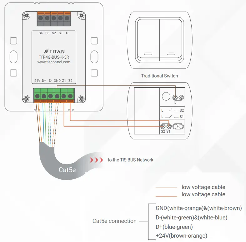
- You can connect 2 digital inputs to any switch or window magnet. Connect the digital input wires to GND, Z1, and Z2 terminals, as is shown in the diagram.

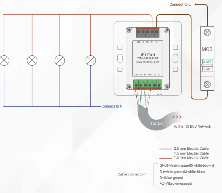
- In the 3R type (panel with relays), connect the 110/220V to the COM terminal and the loads (lights) to the output terminals S1, S2, S3, and S4 as follows:
 LIGHTING CONNECTION
▸ Connect the Live wire to COM
▸ Connect the Loads wire to S1-S4 terminals
▸ Connect the Neutral wire to main neutral in the distributor box.
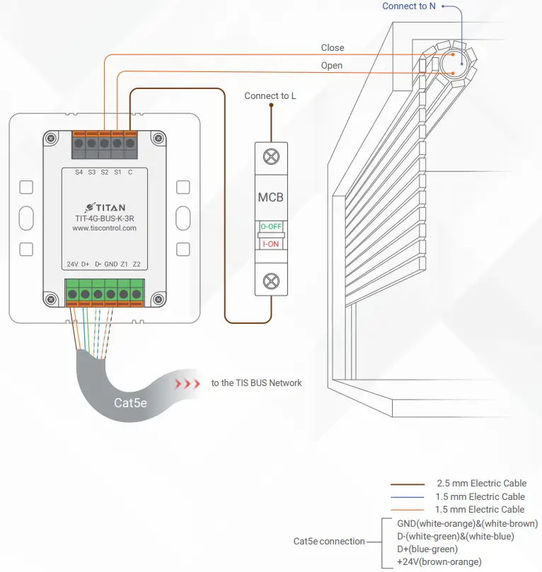
 SHUTTER / CURTAIN CONNECTION
▸ Connect the Supply wire to COM.
▸Connect the Open wire to S1.
▸Connect the Close wire to S2.
▸If the shutter neutral connection exists, can be looped to main neutral in the distributor box. WARNING: Set the curtain function in the software before connecting the wires.
 WARNING: Set the curtain function in the software before connecting the wires.
| Mount the device on the wall using 2 screws on the junction box. | 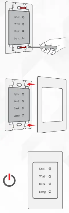 |
| Put the plastic, metal, or glass cover on the main panel and push it to fix it in place. | |
| Turn on the power source. The panel should turn on. |
PAIRING (MANUAL PROGRAMMING)
![]() LIGHTS / SHUTTERS PROGRAMMING
LIGHTS / SHUTTERS PROGRAMMING
You can pair the light channels with any wall panel. To do so, follow these steps:
| Press any channel button on any relay or dimmer module for 6 seconds so that the LED indicator light of that button starts blinking. | 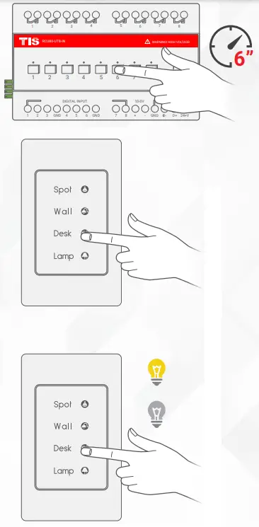 |
| On the Titan/Titania lights pages, shortly tap on any button or press the wall switch that is connected to the dry inputs of the panel addition zones. | |
| Test the feature by tapping the power button for lights ON/OFF or holding it to dim the light (if the channel is dimmable). |
 USER OPERATION
![]() LIGHTS / SHUTTERS / SCENE CONTROL
LIGHTS / SHUTTERS / SCENE CONTROL
Depending on the model, each panel features 2-4 buttons. Following the below instructions, use these light icons to manage your smart home’s lights.
| Single tap to turn a light ON/OFF or to activate a scene. | 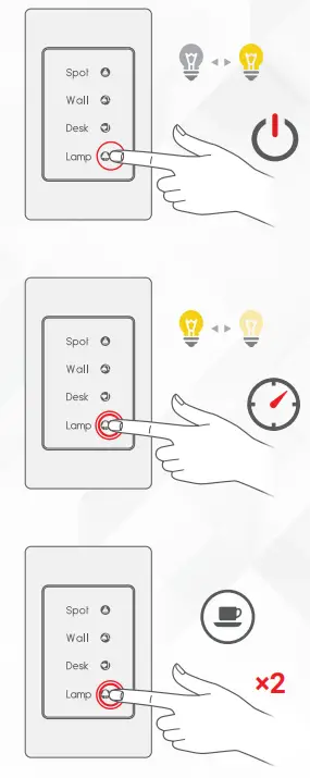 |
| Tap and hold to dim or ramp up light intensity. | |
| Double tap to trigger a special programmed scene. |
 TROUBLESHOOTING
| The panel’s buttons blinks rapidly. | Reason: The panel address conflicts with another device in the TIS network. You need to hold the 1stand 2nd buttons for 6 seconds so that the panel can get a new address. | |
| The panel buttons’ LEDs do not turn ON, and the device is not powered. | Reason 1: There is no TIS-BUS power or no connection to the L/N input (if used AIR bus-3W converter). Reason 2: The TIS 24V power supply is not connected to the TIS-BUS. | |
| The wall panels fail to pair with other devices. | Reason 1: The TIS-BUS connection has a problem, or the wire has a short circuit. Reason 2: The manual programming function is disabled on the device (it is enabled by default). | |
| The wall panels fail to control the devicechannels. | Reason 1: The TIS-BUS connection has a problem, or the wire has a short circuit. Reason 2: The programming address is faulty. |
![]() Copyright © 2022 TIS, All Rights Reserved
Copyright © 2022 TIS, All Rights Reserved
TIS Logo is registered trademark of TIS CONTROL.
All of the specification are subject to change without notice.
TIS CONTROL PTY LIMITED
SA , AUSTRALIA
TIS CONTROL LIMITED
Wanchai, Hong Kong
www.tiscontrol.com


