
![]() OFF-ROAD ACCESSORIES
OFF-ROAD ACCESSORIES
AUXILIARY PANEL
INSTALLATION GUIDE
1988 – 1998 Y60 PATROL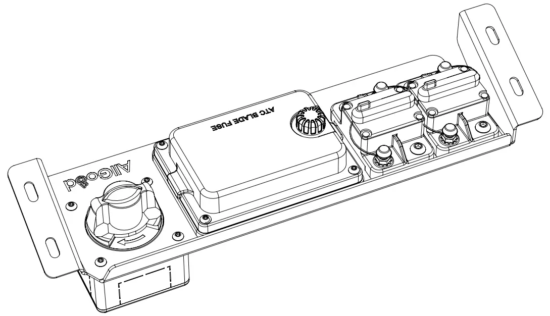
GU Patrol Auxiliary Panel
PLEASE READ CAREFULLY AND FULLY UNDERSTAND THIS GUIDE BEFORE PROCEEDING WITH PRODUCT INSTALLATION!
IMPORTANT: THIS AUXILIARY PANEL AND ALL IT’S ELECTRICAL COMPONENTS HOULD BE INSTALLED BY A QUALIFIED PERSON. THE INFORMATION PROVIDED IN THIS GUIDE IS FOR INFORMATIONAL PURPOSES ONLY AND SHOULD BE PROVIDED TO THE INSTALLER. ALL GOOD OFF-ROAD IS NOT RESPONSIBLE FOR THE CORRECT USE OR FITMENT OF THIS PRODUCT. IT IS THE RESPONSIBILITY OF THE INSTALLER TO ENSURE THE CORRECT INSTALLATION.
IF YOU SHOULD HAVE ANY QUESTIONS ABOUT THE INSTALLATION OF THIS PRODUCT PLEASE CONTACT US AT
[email protected]
www.allgoodoff-road.com.au
PRE-INSTALL
PRODUCT COMPATIBILITY:
This product has been designed to fit the 1987-1997 Nissan Y60 Patrol, gas/petrol/diesel variants.
TOOLBOX:
Intermediate tool kit:
- 1/4” Socket set + 10mm socket
- 10mm Ring spanner (ratcheting ring may come in handy)
- 4mm Allen key or hex driver socket
- Long-nose pliers
- Side-cutters
- Permanent marker or label printer
- Cordless drill + 9mm drill bit
- Electrical tape
- Razor blade
- Nutsert tool (optional)
INSTALLATION TIME:
Depending on the year model of the vehicle, approximately 1-3 hours of fitting time is required.
PARTS LIST:
1x SS Auxiliary panel
6x SS Relay relocation bracket
HARDWARE LIST:
Hardware required to fit relays to vehicle body…
6x M6x12 SS flat washer
6x M6x16 SS Allen bolts
6x Zinc Nutserts + 1x makeshift nutsert installation tool (see nutsert installation instructions)
Hardware required to fit panel to vehicle body…
4x M6x16 SS Allen bolt
4x M6x12 SS flat washers
4x M6x13 SS flanged serrated nuts
Optional additional parts are not included…
– Rubber-lined p-clamps, for holding airconditioning line captive
– 10mm ID ribbed electrical split conduit, for sheathing airconditioning line
***NO ELECTRICAL COMPONENTS ARE INCLUDED***
NUTSERT INSTALLATION
Nutserts are a permanent solution to adding thread to a sheet metal body, which can be installed in new or existing holes. Similar to a rivet, the nutsert is deformed during the swaging process, which tightly compresses around the sheet metal hole, fixing the nutsert in position. A makeshift nutsert tool is to be used for this installation, made up of the provided hardware and by following the below steps…
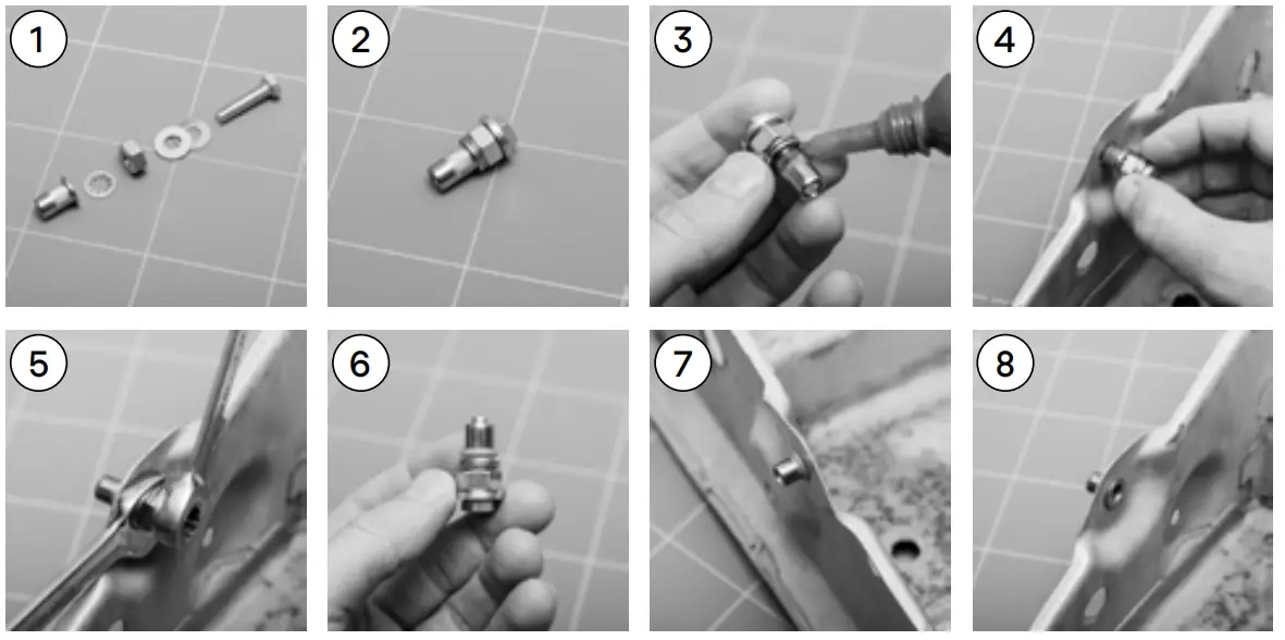
- This is the nutsert and makeshift tool laid out in the correct order of assembly.
- Assemble as per the order in the previous step, ensuring that all parts are finger-tight and captive. The nursery is almost ready to be installed.
- It is recommended that a thin bead of thread locker is applied around the underside of the nursery’s mating flange – Depending on the thread locker used, it may need time to set.
- Ensure that the hole in which the nutsert is being installed matches the barrel diameter of the nutsert as closely as possible, the fit should be snug. The hole may need to be drilled out to suit (eg. For this M6 nutsert we have drilled a Ø9mm hole). Make sure that the hole is deburred for best fitment, and that all parts are free from dirt and grease prior to installation. It is also recommended that any new holes drilled are painted prior to installing nutserts to avoid rust or corrosion.
- Using 2 spanners of the correct size, hold the spanner on the nut stationary whilst tightening the bolt head using the outermost spanner (we have used both a 13mm open-ended, and a 10mm ratcheting ring spanner, which could be substituted by a socket, to make installation both quicker and easier). During this swaging process make sure that the lip on the nutsert is flush up against the mounting surface. Tighten the bolt head until nice and firm, but do not over-tighten, checking that the nutsert no longer spins freely and is firmly fixed in the hole.
- This is an example of a correctly swaged nutsert.
- This is how the nutsert should look from the backside (in some cases not always visible) with the correct amount of flare, tightly sandwiching the sheet metal.
- This is how the nutsert should look from the front side, with the outer lip flush up against the sheet metal body.
- Nutsert installation is now complete*
PREPARING FOR INSTALLATION
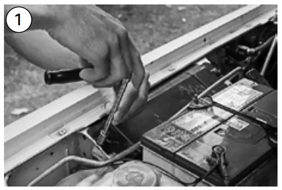 | 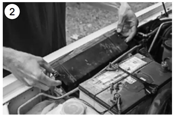 |
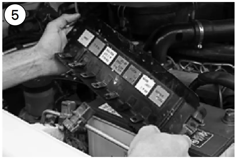
| Remove 4x bolts from the factory relay cover. If applicable, set aside any aircon hardline clips/clamps. | Tilt the factory relay cover towards the start battery to expose the relays on the underside. |
 | 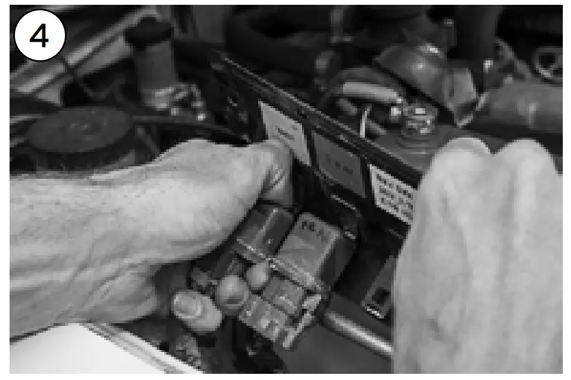 |
| Label each of the factory relays accordingly, using a marker or label printer before removing them from the cover. | Remove all of the relays from the underside of the cover by carefully sliding them off the mounting tabs, then set them aside for later steps. |
 | 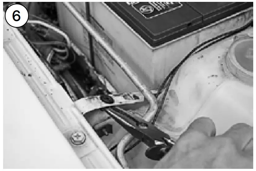 |
| Remove all of the relays from the underside of the cover by carefully sliding them off the mounting tabs, then set them aside for later steps. | Remove 4x factory screw-grommets from the cover’s original mounting points. This is achieved by compressing the fins on each grommet whilst levering it out of it’s hole. |
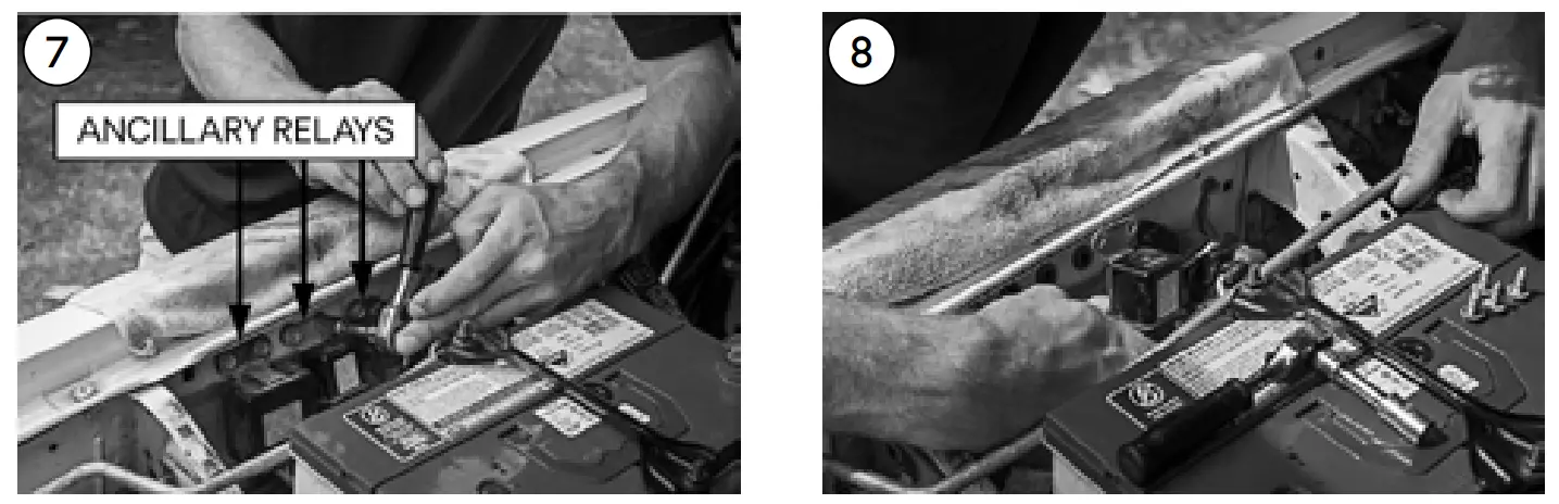 | |
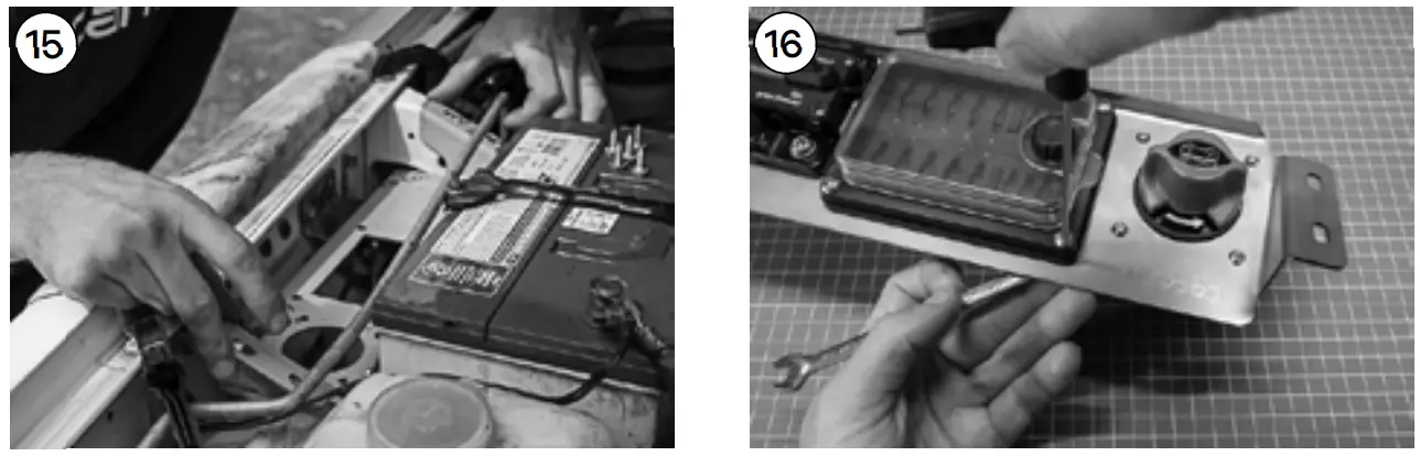
| In most cases, the factory ancillary relays in this location will need to be relocated in order to mount the auxiliary panel and relocate the factory accessory relays. | Remove each of the relays from this and set aside for further steps. |
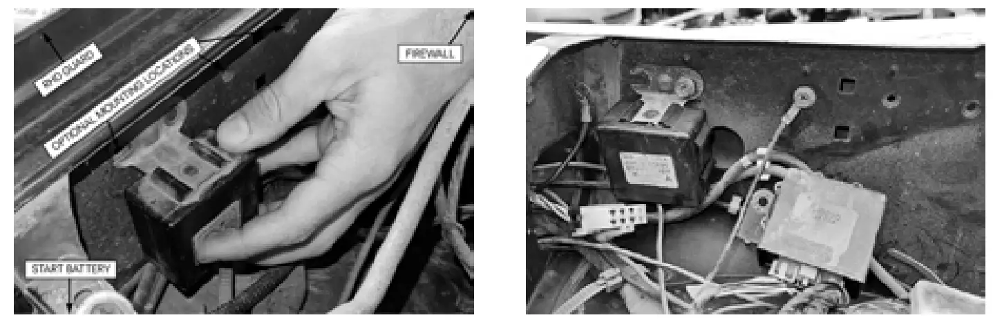 | |
Note: The new mounting location may vary depending on the year model of your vehicle. We have chosen to mount the relays on the inner guard closer to the firewall. Drilling additional mounting holes may also be required. Alterna- In some instances, the sheathing on the factory harness may need to be split-and re-wrapped in order to achieve further movement from the wiring. | Tively, these relays can be tucked underneath the auxiliary panel and cable-tied captive to the main wiring harness. |
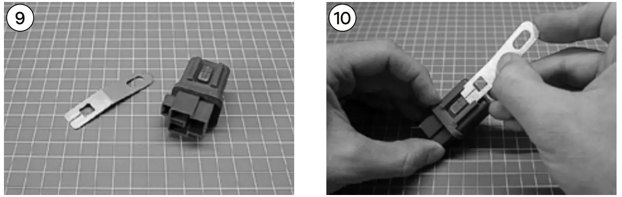 | |
| Supplied relocation bracket and factory Nissan relay. At this step remove any protecting film and or residue from the bracket using thinners or isopropyl alcohol. | Fit the relay bracket to the relay by sliding the tab end of the bracket into the channel on the back side of the relay until seated. |
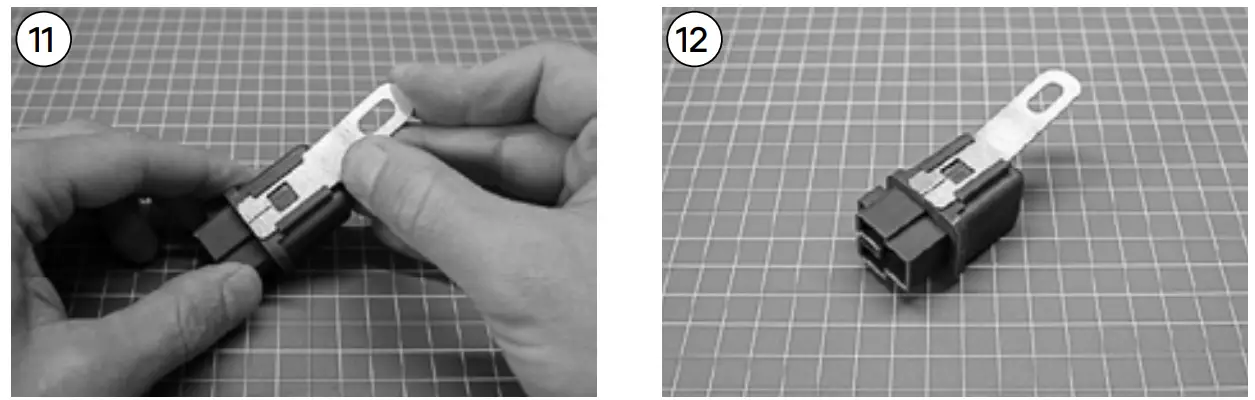 | |
| Relay bracket in place, pictured. The square cut-out in the center of the tab locates on the peg of the relay. Repeat steps 9-10 for the remaining relays. | As pictured, ensure the fold in the bracket is facing away from the relay. This relay is now ready to be installed* |
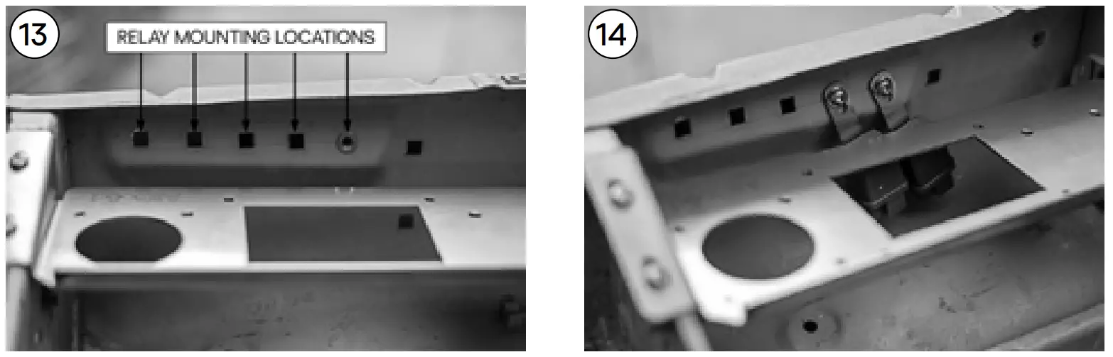 | |
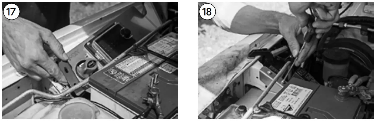
| Recommended alternate mounting locations for the factory relays. To mount the relays M6 nutserts may need to be installed at these locations – Refer to the ‘Nutsert Installation’ page. | Relays may need to be installed at an angle to allow enough slack in the factory wiring harness. If enough slack cannot be achieved, the harness sheathing may need to be manipulated to allow for further movement. |
 | |
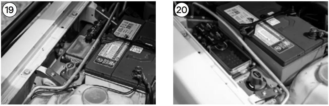
| Test fit the aux panel in position, making sure that any of the electrical components re-located in the previous steps do not come in contact with the panel. | At this step mount any electrical components to the aux panel. Make sure to leave any protective film on the panel intact until all works have been carried out to prevent marking. |
 | |
| Once all electrical components have been mounted to the aux panel It can then be re-fitted to the vehicle’s body. | Fix the aux panel in position to body using the supplied M6X16 SS Allen bolts, M6 flat washers, and M6 serrated flange nuts, Include any aircon hardline clips/clamps set aside in earlier steps. |
 | |
| Note: It is recommended that the factory aircon line is mounted using rubber-lined P-clamps (not supplied), or is very gently manipulated away from anywhere that might contact. Cover with conduit if necessary. | The installation of your auxiliary panel is now complete*. Wire in any auxiliary accessories and enjoy! |
NOTES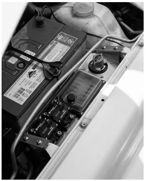 BE SURE TO TAG @ALLGOOD_OFFROAD IN YOUR INSTALLS AND OFF-ROAD SNAPS!
www.allgoodoff-road.com.au


