![]()
MD2413-MX INSTALLATION INSTRUCTION
![]()
![]()
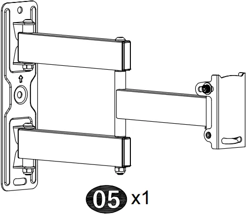
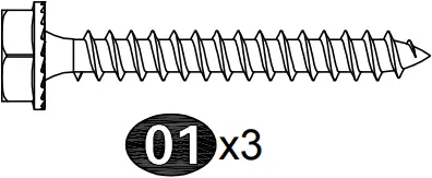
x3 x1
 Max:400x400mm/16×16″
Min:75x75mm/3×3″

![]()

(C1)
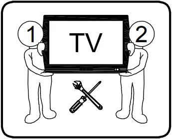
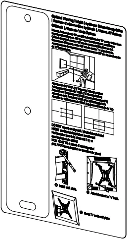
Before getting started, let’s make sure this mount is perfect for you!
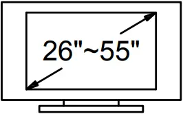
| 1 Is your TV VESA equal to/greater than 75x75mm/3×3″ and equal to/less than 400x400mm/16×16″? | 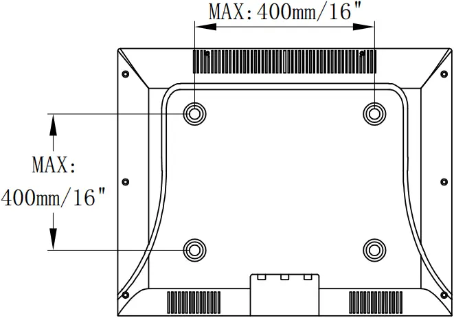 Yes — Perfect! | |
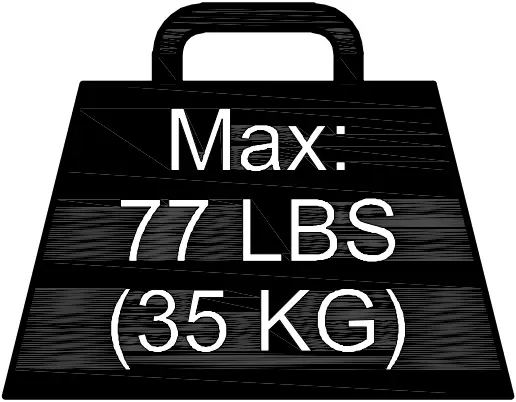
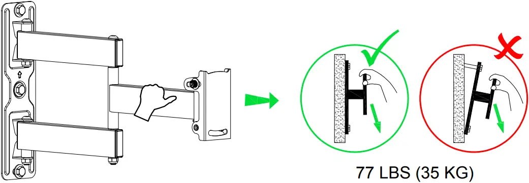
| 2 Does your TV (including accessories) weigh less than 77 LBS (35 KG)? | 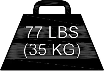 Yes — Perfect! | |
| 3 What is your wall made of? | ||
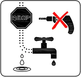
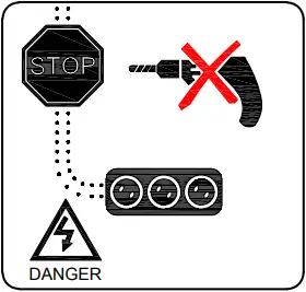
| DO NOT install into drywall alone | ||
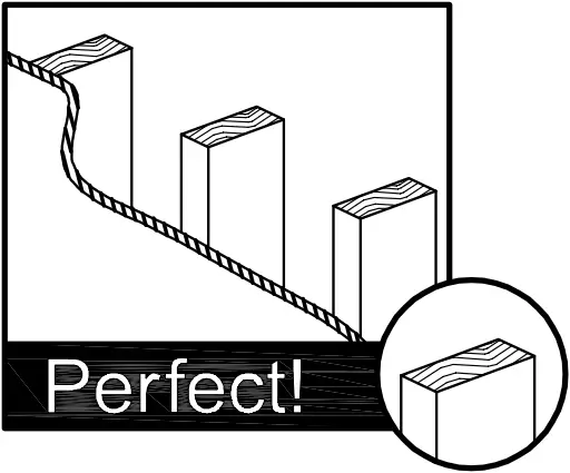 Drywall with wood studs?
| ||
| 4 Installation Tools (Not Included) |
| |
| Wood Stud Install |
| |
| Concrete Install |
| |
| 5 Safety Caution | Please read this instruction carefully before installation.
| |
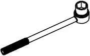 Socket Wrench
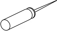 Awl
Awl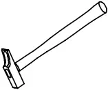 Hammer
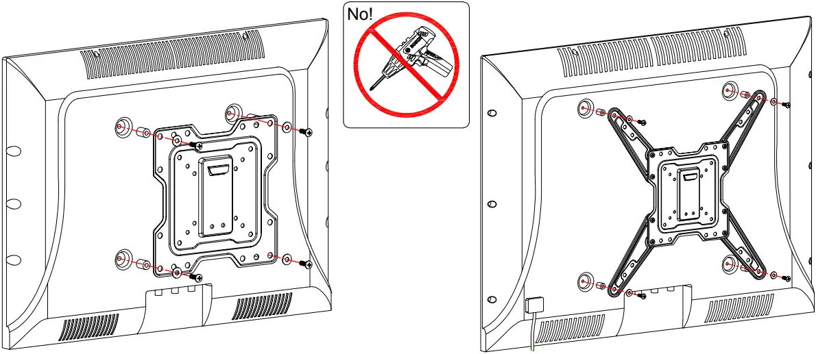
STEP 1 Attach TV Plate to TV
Parts and Hardware
![]() WARNING: This product contains small items that could be a choking hazard if swallowed. Before starting assembly, verify all parts are included and undamaged.
WARNING: This product contains small items that could be a choking hazard if swallowed. Before starting assembly, verify all parts are included and undamaged.
NOTE: Not all hardware included will be used.
Allen Key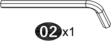
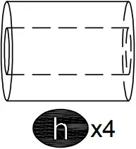
Extended Arm Screws
M6x8mm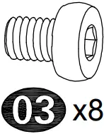
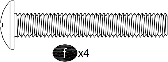
TV Screws
M4x12mm M4x30mm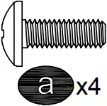
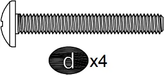
M6x12mm M6x35mm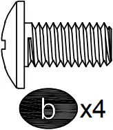
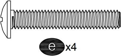
M8x25mm M8x45mm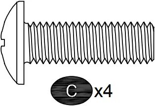
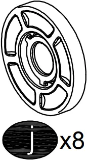
Spacers
M6x17mm M8x22mm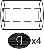
10mm 2.5mm
Washers
M4 M6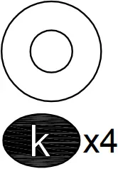
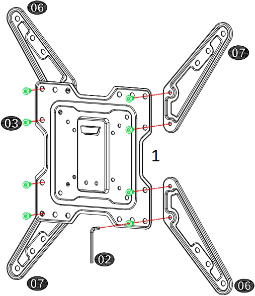
TV Plate Unit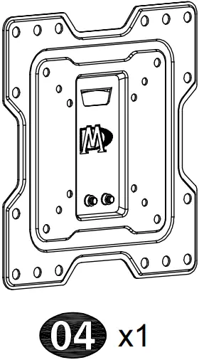
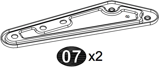
Extended Arm Extended Arm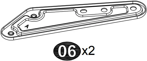
1-1 Disassemble TV Plate Unit into Two Pieces
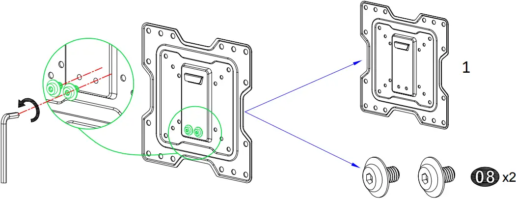
- TV Plate
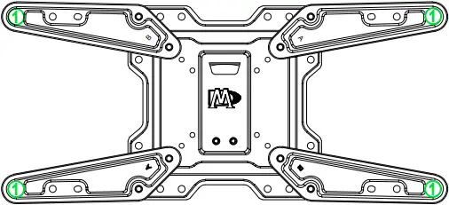
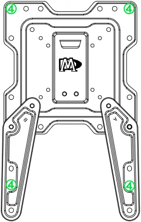
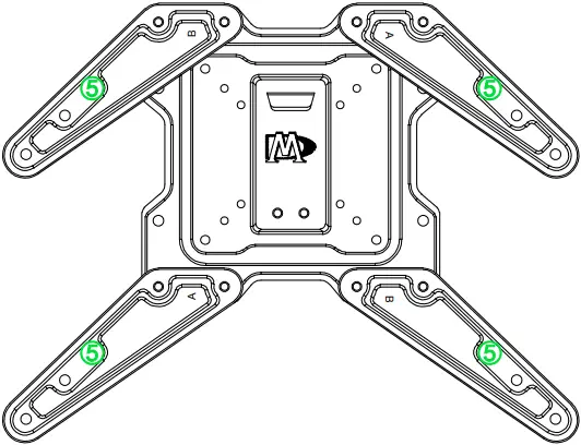
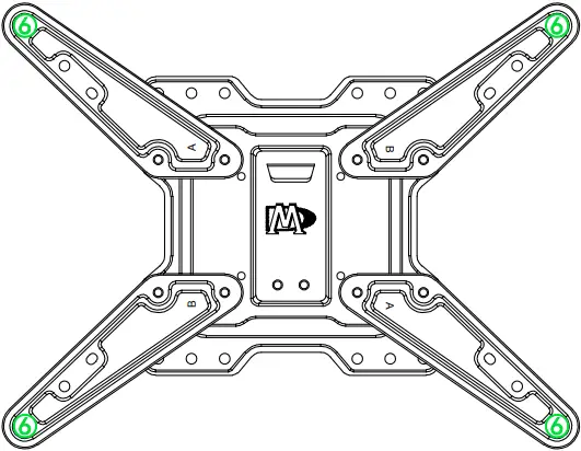
1-2 Choose Configuration
400mm x 200mm
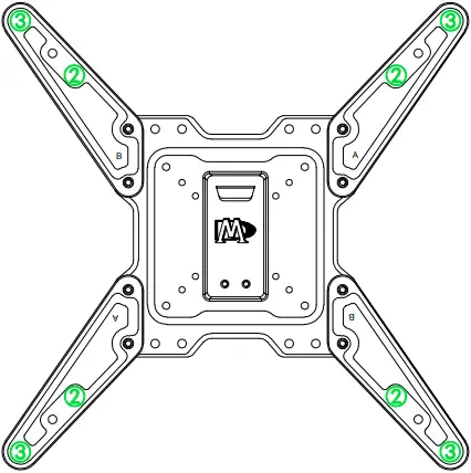
300mm x 300mm
400mm x 400mm
200mm x 300mm
75mm x 75mm
100mm x 100mm
100mm x 200mm
150mm x 150mm
200mm x 100mm
200mm x 150mm
200mm x 200mm
300mm x 200mm
400mm x 300mm
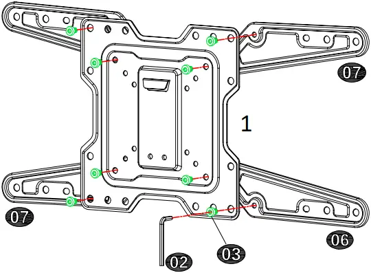
Extended Arms Assembly Example (For reference)
- TV plate
- TV plate
1-3 Select TV Screws
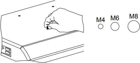
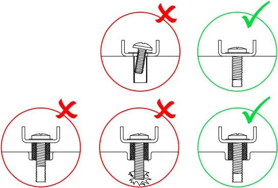
1-4 Need Spacer?
[I] No, go to PAGE 5 (I) for detailed combination.
- Bracket
- Short Screw
- Washer
- TV back
[II] Yes, go to PAGE 5 (II) for detailed combination.
- Bracket
- Long Screw
- Washer
- Spacer
- TV back
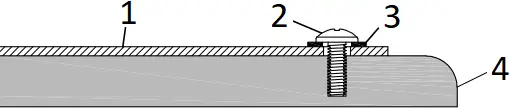
1-5 Attach TV Plate to TV Back
(I) Screw and washer
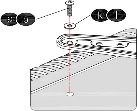
(II) Spacer(s), screw and washer
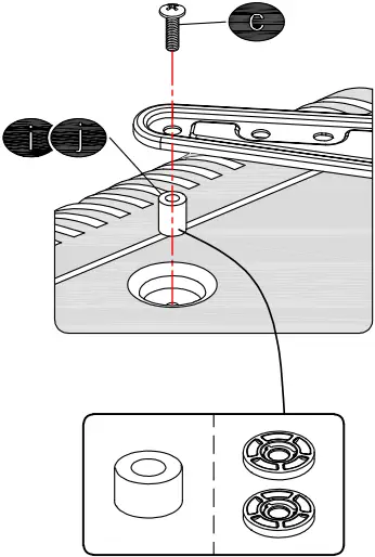
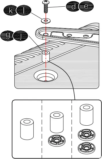
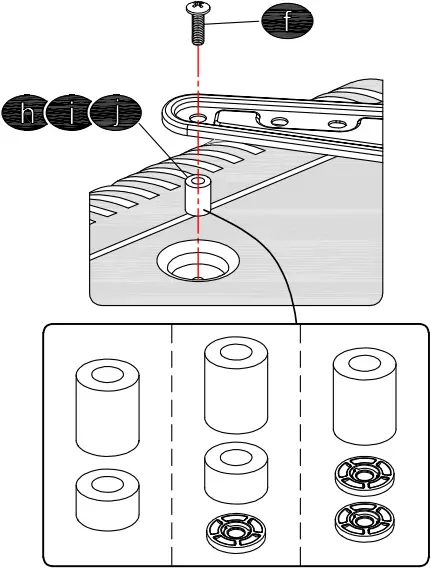
Tips: If you need to combine M6(e) or M8(c/f) screw with 2.5mm spacer(j), you have to remove the inner circle.
STEP 2 Attach Wall Plate to Wall
 For wood stud installation, follow STEP 2A
 For concrete installation, follow STEP 2B on PAGE 8
Parts and Hardware
Mounting Template Wall plate
Lag Bolt M7x55mm
| Concrete wall anchor (NOT INCLUDED) | |
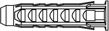 Concrete Wall Anchor |
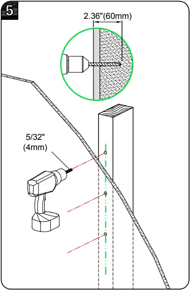
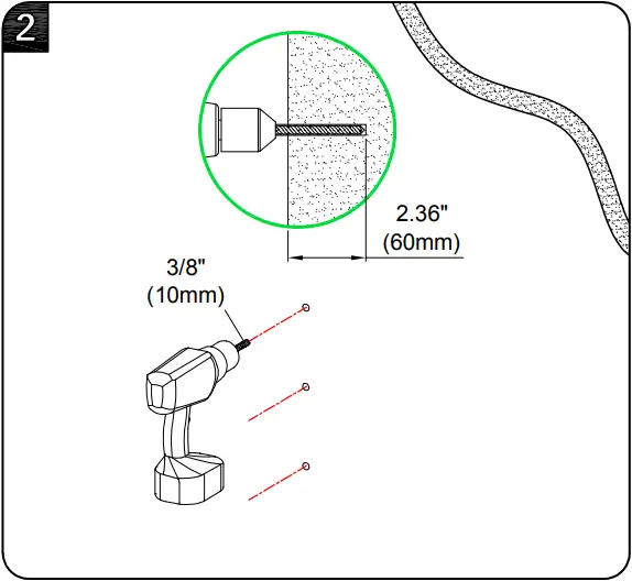
STEP 2A Wood Stud Installation
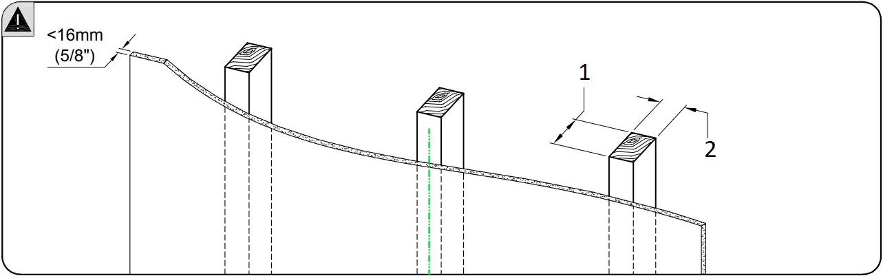
- Min. Wood Stud Size:
nominal 4″(102mm)
actual 3 1/2″(89mm) - Min. Wood Stud Size:
nominal 2″(51mm)
actual 1 1/2″(38mm)
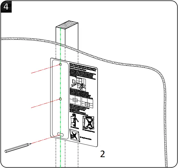
- Centre line
- Mounting Template
![]() CAUTION: To avoid potential personal injury or property damage:
CAUTION: To avoid potential personal injury or property damage:
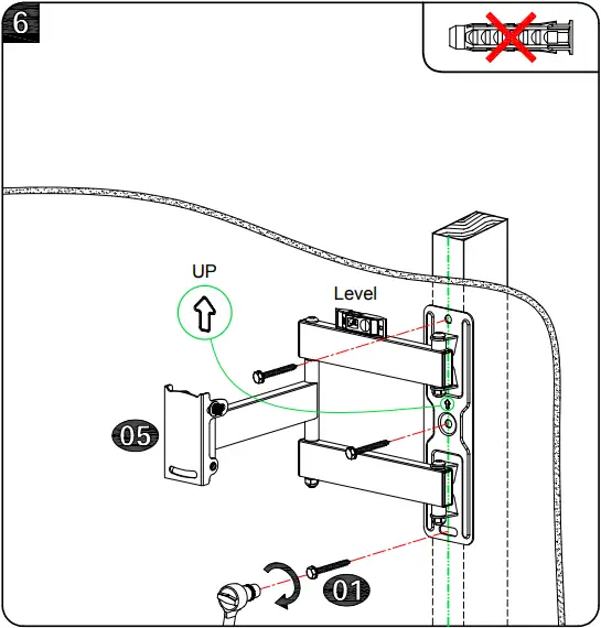
All 3 lag bolts (01) MUST BE firmly tightened to prevent unwanted movement of the wall plate assembly. Ensure the wall plate assembly is securely fastened to the wall before continuing on to the next step.
To prevent the TV falling down, the direction of the arrow should be upward as shown.
Go to Step 3 on PAGE 9.
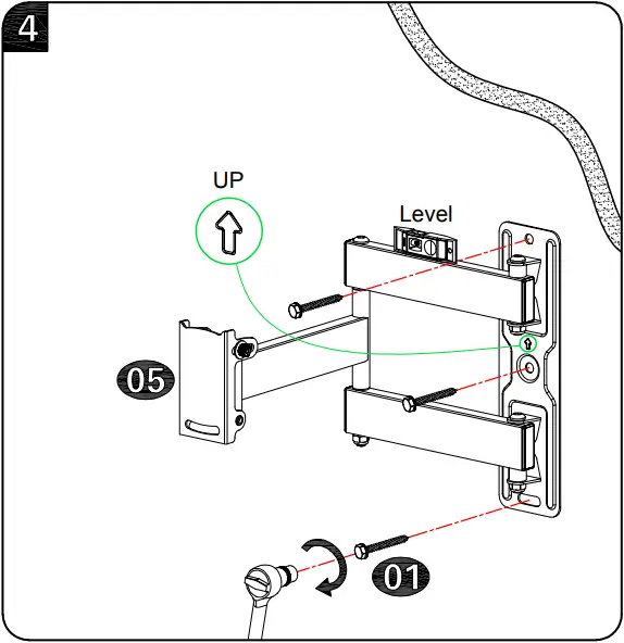
STEP 2B Solid Concrete Wall Installation
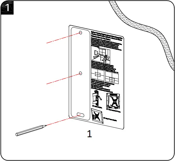
- Mounting Template
![]() CAUTION: To avoid potential personal injury or property damage:
CAUTION: To avoid potential personal injury or property damage:
All 3 lag bolts (01) MUST BE firmly tightened to prevent unwanted movement of the wall plate assembly. Ensure the wall plate assembly is securely fastened to the wall before continuing on to the next step.
To prevent the TV falling down, the direction of the arrow should be upward as shown.
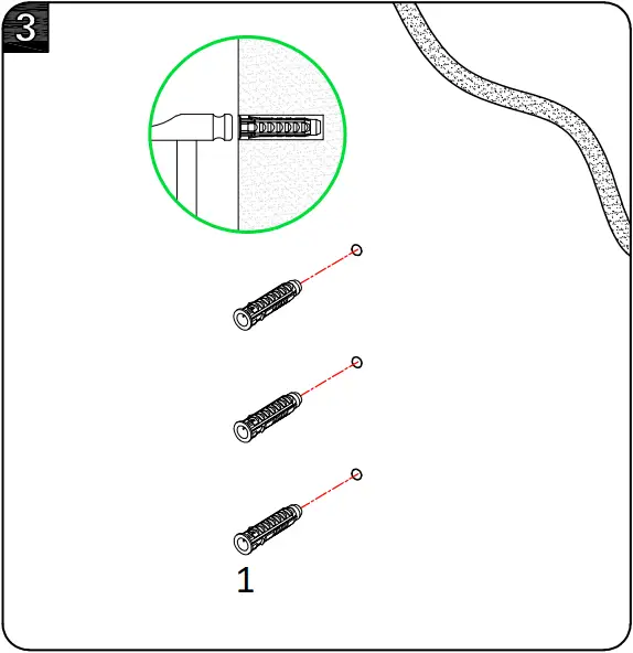
- Concrete Wall Anchor
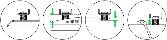
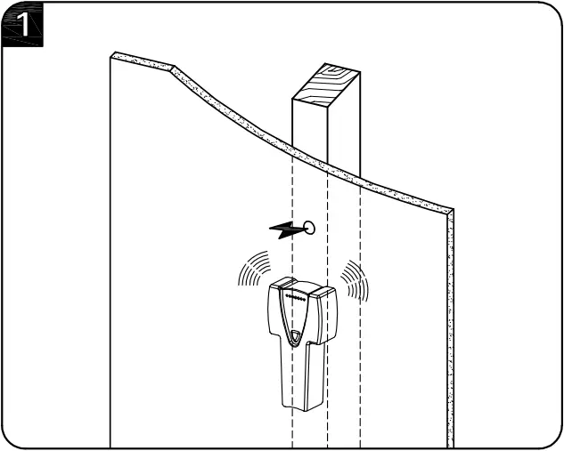
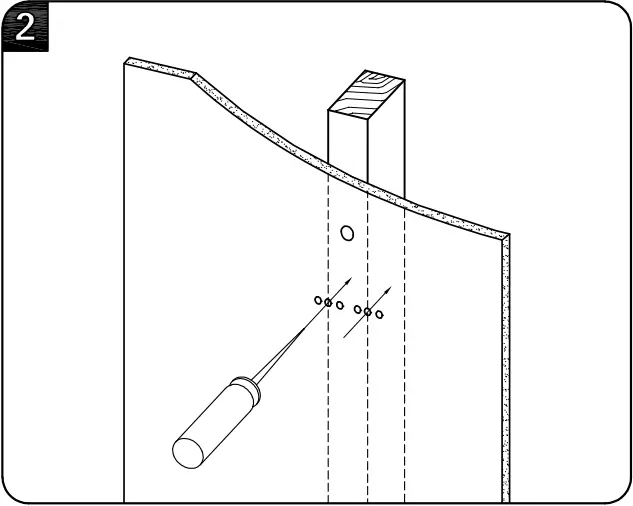
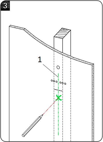
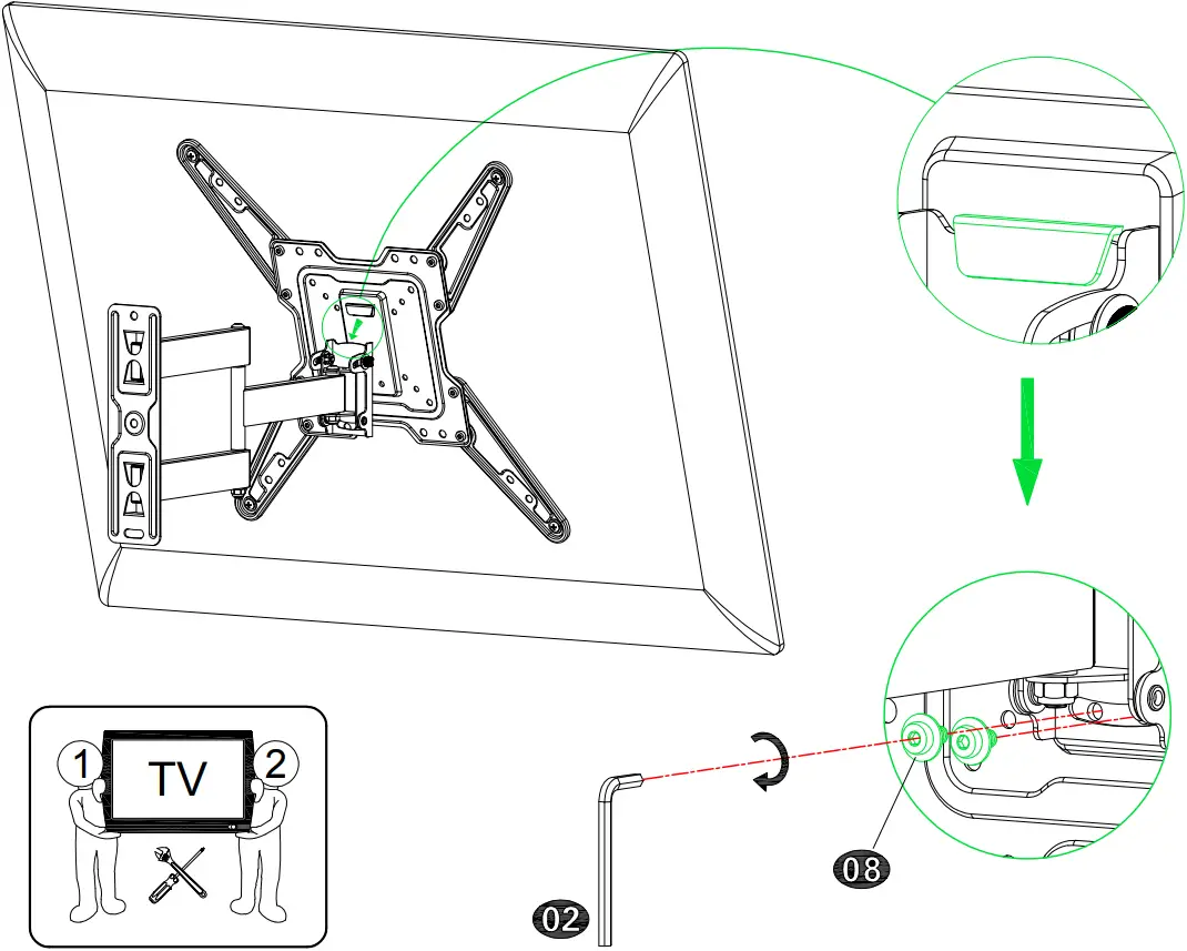
STEP 3 Hang and Secure TV to Wall Plate
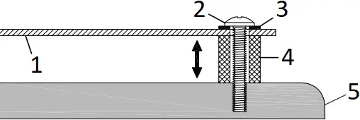
Before hanging TV, please conduct “wall plate installation integrity test” first.
STEP 4 Adjustments
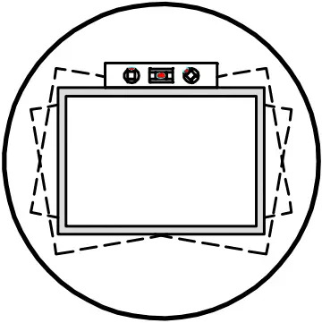
4-1 TV leveling adjustment (±4°):
Loosen 2 leveling bolts on the rear of TV plate by maximum 2 turns, adjust to level, and retighten to secure.
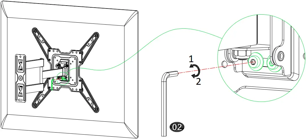
- Loosen
- Tighten
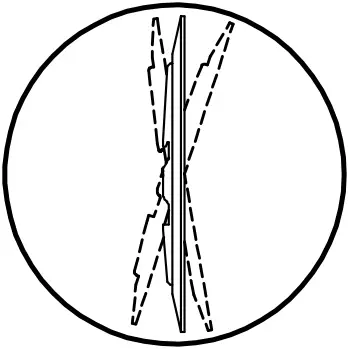
4-2 Tilting angle adjustment (+5°/-15°):
Pull TV to your desired angle then fasten 2 tilting bolts with Allen key (02).
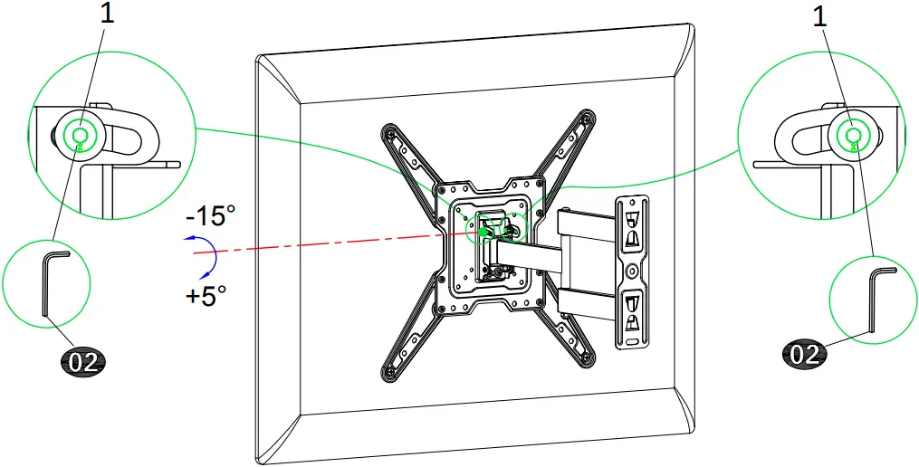
- Tilting bolts
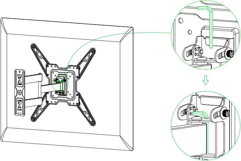
 Allen key storage: For easy adjustment, you might put the Allen key on the wall plate as illustration.
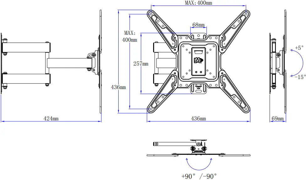
Product dimensions: