![]()
VLWP-3HVG-TR
18G, 3×1 2xHDMI/VGA Wall Plate w/Auto
-Switching, USB2.0, POC (2-Gang US Decora,
40M@4K, 70M@1080P) White color Tx/Rx pair
User Manual
VER 1.1
VLWP-3HVG-TR 18G, 3×1 2xHDMI/VGA Wall Plate w/Auto Switching
Thank you for purchasing this product
Please read these instructions carefully for optimum performance and safety before connecting, operating, or adjusting this product. Please keep this manual for future reference.
A surge protection device is recommended.
This product contains sensitive electrical components that electrical spikes may damage surges, electric shocks, lightning strikes, etc. Use of surge protection systems are highly recommended to protect and extend the life of your equipment.
Introduction
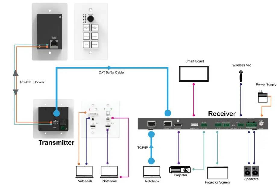
The product is a multi-function AV intelligent education system. It offers 2HDMI and VGA video extension, video switching, system control, and analog audio amplification. Uncompressed video and audio can be transmitted up to 230ft/70m.
This design of HDBaseT™ technology allows for total usage of HDMI and controls over CAT5e/6/6A cable. The product supports Web GUI and panel button control.
Transmitter support HDCP 1.4 and HDCP2.2 and can be switched manually, auto, hybrid, or priority. And the maximum distance can be up to 70m at 1920×1200@60Hz or 40m at 4K @ 30 Hz.
The receiver supports a microphone input, analog audio output, 2×30 at 4 ohms speaker output, and Relay control to the projector screen rise and fall or RS-232 control to the display power on and off. A USB port on the receiver will transmit interactive display connections to the transmitter. Control Panel supports volume control and system control. At the same time, it can support 2 HDMI and one VGA input selection.
Features
☆ HDMI 1.4b, HDCP 2.2, and HDCP 1.4 compliant.
☆ Video resolutions up to 4K2K@30Hz, 1080p@120Hz and 1080P 3D@60Hz.
☆ Audio up to 7.1 channels of High Definition audio pass-through (LPCM, Dolby TrueHD, and DTS-HD Master Audio).
☆ HDBaseT™ over a single CAT5e/6/7 cable up to 230ft/70m.
☆ Support multi-VESA Standard VGA formats input.
☆ Supports MIC input.
☆ 2x30watts@4 ohms amplifier output.
☆ Supports interactive display USB pass-through.
☆ Supports Web GUI control.
☆ Supports control panel volume control and system control.
☆ Supports relay control.
☆ Supports RS-232 control
Package Contents
- 1× HDMI Extender Transmitter
- 1× HDMI Extender Receiver
- 1× 24V/3.75A DC Power Supply
- 2× Mounting ears
- 1× User Manual
Specifications
| Technical | |
| HDMI Compliance | HDMI 1.4 |
| HDCP Compliance | HDCP 2.2/HDCP 1.4 |
| Video Bandwidth | 10.2 Gbps |
| Video Resolution | up to 4K2K@30Hz,1080P@1201-1z and 1080P 3D@60Hz |
| Color Space | RGB, YCbCr 4:4:4, YCbCr 4:2:2 |
| Color Depth | 8/10/12-bit |
| HDMI Audio Format | LPCM 2/5.1/7.1CH, Dolby Digital, DTS 5.1, Dolby Digital+, Dolby TrueHD, DTS-HD Master Audio, Dolby Atmos, DTS:X |
| ESD Protection | Human body model — ±-8kV (Air-gap discharge) & ±-4kV (Contact discharge) |
| Connections | |
| Connections | Inputs: 2x HDMI IN Type A (19-pin female] lx VGA (DB15 VGA female] lx AUDIO IN [3.5mm Stereo Mini-jack] lx RS-232/POWER [R145] Outputs: lx HDBaseT Out [R145] |
| Receiver | Inputs: lx HDBaseT in [R145] lx MIC IN [Screw Terminal] lx USB [USB A TYPE] lx TCP/IP [RJ45] Outputs: lx HDMI OUT Type A [19-pin female] lx RS-232 [Screw Terminal] lx RELAY [Screw Terminal] lx AUDIO OUT [Screw Terminal] lx 2x30watts@4 ohms amplifier output [Screw Terminal] |
| Mechanical | |
| Housing | Metal Enclosure |
| Color | Transmitter: White, Receiver: Black |
| Dimensions | Transmitter: 115.9mm [W] x 114.3mm [D] x 38.7mm [H] Receiver: 250mm [W] x 104mm [D] x 30mm [H] |
| Weight | Transmitter: 305g, Receiver: 758g |
| Power Supply | Input: AC100 – 240V 50/60Hz, Output: DC 24V/3.75A (US/EU standards, CE/FCC/UL certified) |
| Power Consumption | 75W (max) |
| Operating Temperature | 32 – 104° F / 0 – 40° C |
| Storage Temperature | 4 – 140° F / -20 – 60° C |
| Relative Humidity | 20- 90% RH (no condensation) |
Operation Controls and Functions
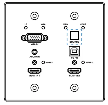
5.1 Transmitter Panel
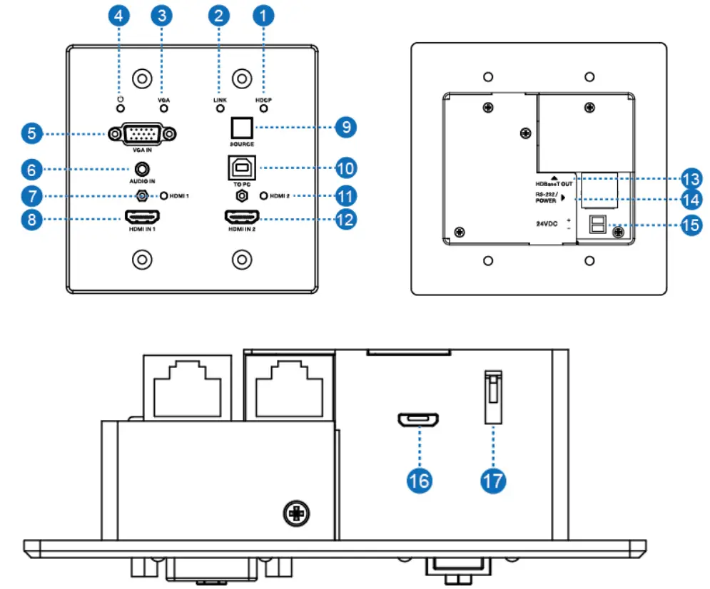
| Number | Name | Function description |
| 1 | HDCP LED | HDCP compliance indicator. •OFF: HDMI input is not carrying HDCP content. •ON: HDMI input takes HDCP content. |
| 2 | LINK LED | HDBaseT Link status indicator. •OFF: No Link. •GREEN: Link successful. •Blink GREEN: Link abnormal. |
| 3 | VGA LED | VGA signal indicator. •OFF: No +5V HPD or VGA signal detected on input. •FLASHING: +5V HPD or VGA signal is detected. •GREEN: VGA is active input, and VGA signal is seen. |
| 4 | POWER LED | System power indicator. |
| 5 | VGA IN | Connect to VGA source. |
| 6 | AUDIO IN | Connect to external audio source for VGA signal. |
| 7 | HDMI I LED | HDMI 1 signal indicator. •OFF: No +5V HPD or HDMI signal detected on input. •FLASHING: +5V HPD or HDMI signal is detected. •GREEN: HDMI is active input, and HDMI signal is detected. |
| 8 | HDMI 1 IN | Connect to HDMI source device. |
| 9 | SOURCE | Press it to select one source. |
| 10 | TO PC | Connect PC to transmit USB control signal from the Receiver USB device in. |
| 11 | HDMI 2 LED | HDMI 2 signal indicator. •OFF: There is no +5V HPD or HDMI signal detected on the input •FLASHING: +5V HPD or HDMI signal is detected. •GREEN: HDMI is active input, and HDMI signal is detected |
| 12 | HDMI 2 IN | Connect to HDMI source device. |
| 13 | HDBaseT OUT | Connect to HDBaseT Receiver with a Cat5e/6/7 cable. |
| 14 | RS-232/POWER | Connect to Control Panel via CATSe/6/7 cable. |
| 15 | 24VDC (OPTIONAL) | Connects 24V/1A adaptor to AC wall outlet for power supply. |
| 16 | Micro-USB | For firmware updated use. |
| 17 | DIP SWITCH | Select upgrade type. |
5.2 Receiver Panel
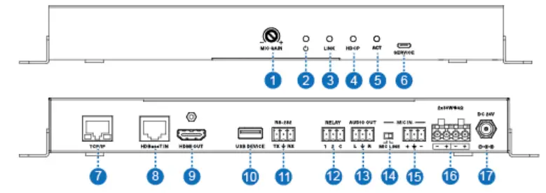
| Number | Name | Function description |
| 1 | MIC GAIN | Set the MIC input gain. |
| 2 | POWER LED | System power indicator. |
| 3 | LINK LED | HDBaseT Link status indicator. •OFF: No Link. •GREEN: Link successful. •Blink GREEN: Link abnormal. |
| 4 | HDCP LED | HDCP compliance indicator. •OFF: HDMI input is not carrying HDCP content. •ON: HDMI input takes HDCP content. |
| 5 | ACT | System work indicator. •OFF: System standby or power off. •Blink GREEN: System working. |
| 6 | SERVICE | For firmware updated use. |
| 7 | TCP/IP | Connect to a PC and access the Web GUI for system settings. |
| 8 | HDBaset IN | Connect to HDBaseT Transmitter with a Cat5e/6/7 cable. |
| 9 | HDMI OUT | Connect to an HDMI display device. |
| 10 | USB DEVICE | Connect to an interactive display. |
| 11 | RS-232 | RS-232 control for the display. |
| 12 | RELAY | To control the projector screen’s rise and fall. |
| 13 | AUDIO OUT | Connect to a speaker. |
| 14 | MIC LINE SWITCH | •When the switch is set to “MIC,’ the microphone input is used to connect a dynamic microphone. •When the switch is set to “LINE,- the microphone input is used for connecting a line-level audio source or wireless microphone output. |
| 15 | MIC IN | Using Phoenix terminal cable to connect microphone input. |
| 16 | 2X30 watts @4 0 | Connect to speaker out. |
| 17 | DC 24V | Connect 24V/3.75A adaptor to AC wall outlet for power supply. |
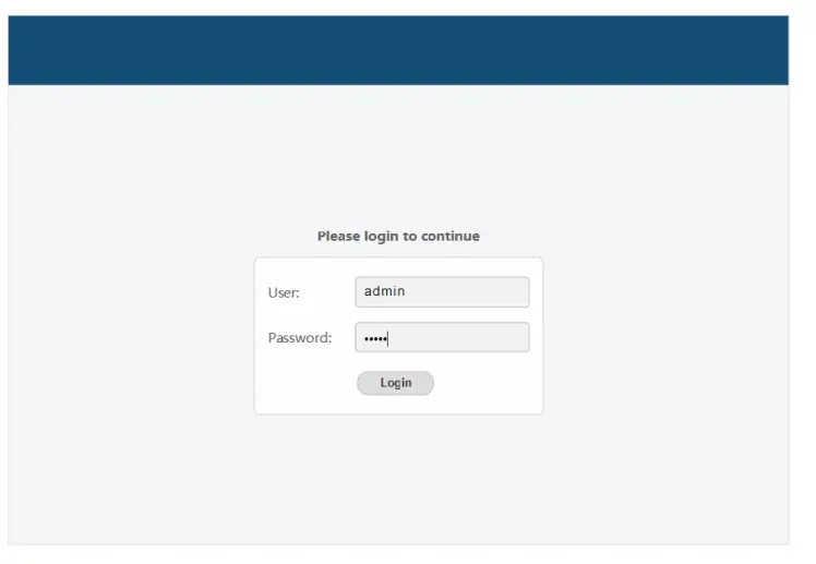
Web GUI User Guide
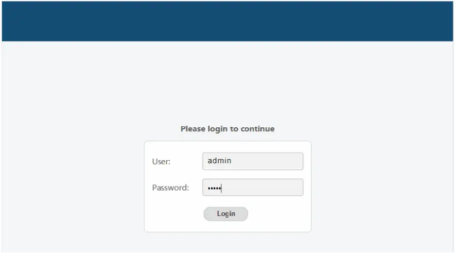
The product can be controlled via Web GUI through TCP/IP port. The default IP address is 192.168.2.100. When the product has finished connection. You can set the IP address to your PC/laptop Internet Explorer and click “Search.” to enter the Web GUI login page. On the login page, you need to set the ‘User’ and ‘Password.’ The admin’s default ‘User Name’ and ‘Password’ are both ‘admin.’ When you set it over, you need to click the ‘Login’ button to enter the Web GUI function page. The login page likes below:
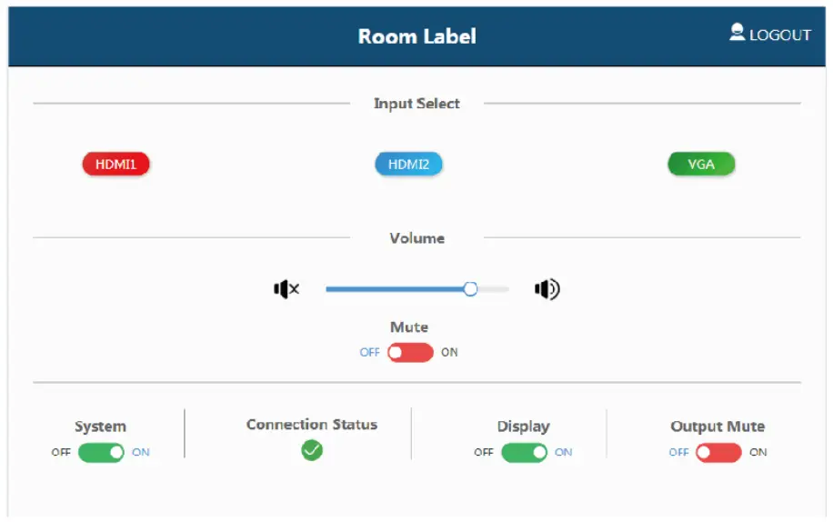
MAIN page
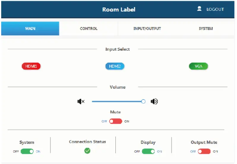
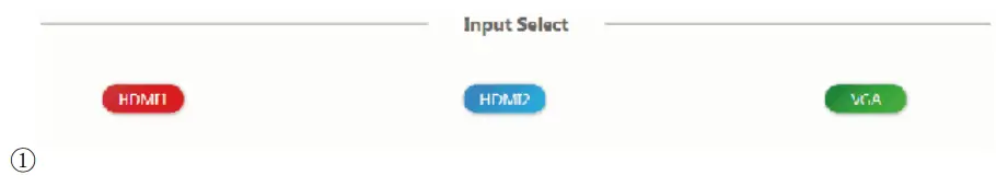
Shows the status of the input signal.
Green: The input port has connected an active signal.
Blue: The input port has connected success but no active signal.
Red: The input port has not connected.

Volume control outputs for the amplifier and the audio extractor. Adjusting the slider to increase or decrease results in the amplifier and the audio extractor.
Toggle is the Mute setting to silence the amplifier and the audio extractor outputs. The mute setting does not silence the audio on the HDMI output line.
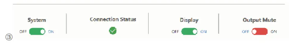
System – runs the system on/off subroutine when switching the toggle. (see section 7)
Connection Status – indicates when the connection is well about the web server.
Display – Runs the show on/off subroutine when switching the toggle, see section 8.
Output Mute –turns off the video output but does not mute audio.
CONTROL page
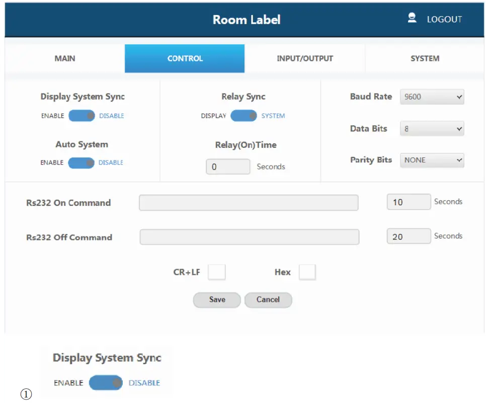
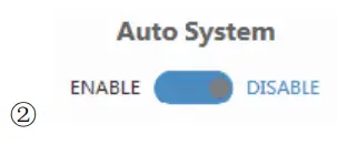
Display System Sync: When the toggle is in the ‘ enable’ position, the display on/off subroutine will run the system subroutine on/off every time. (See section 7)
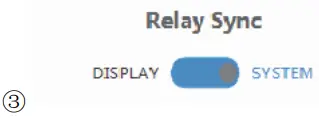
Auto System: When the toggle is in the ‘ enable’ position, and the system is in standby status, if a new signal is connected, the system will change to active and fully controllable. When the toggle is in the ‘ disable’ position and the system is in standby status, if a new signal is connected, the system status won’ t change.
Relay Sync: Sets the relays to either be triggered with the display subroutine on/off or the system subroutine on/off. (see sections 7 and 8)
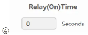
Relay (On) Time: Sets the amount of time that the relay contacts will stay close.
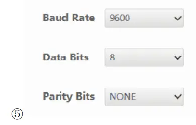
The RS-232 communication settings for the RS-232 port.
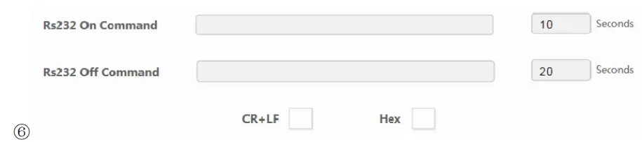
RS232 On Command: Sends out data when Display On subroutine is called.
RS232 Off Command Sends out data when the Display Off subroutine is called.
CR + LF: Appends a carriage return and line feed character to the end of the input strings as they are sent out.
Hex: The commands can be input as hexadecimal numbers when the Hex checkbox is marked.

Save: After any setting has been made, the settings must be saved by pressing the ‘ Save’ button.
Cancel: Wait for the popup window to close automatically before continuing to make another set while it saves.
INPUT/OUTPUT page
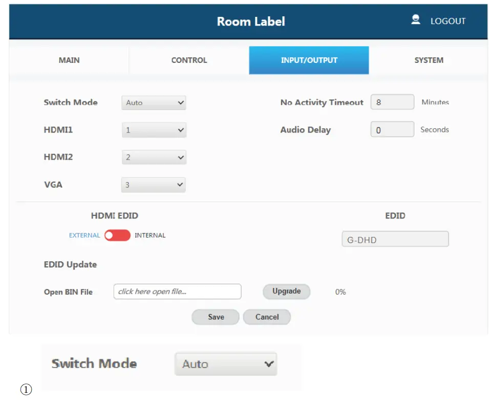
Switch Mode: Sets how the switcher plate will change between input signals.
It includes ‘Auto’ mode and ‘Manual’ mode.
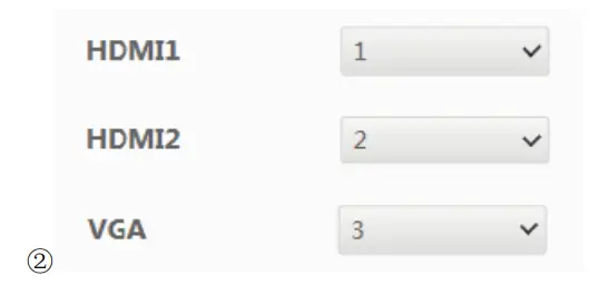
Sets the priority to use when the switch mode is set to priority mode. 1 is the The highest priority and 3 are the lowest.

No Activity Timeout: Sets the amount of time it will take for the unit to turn itself off when there is no detected input signal.
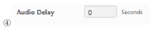
Audio Delay: Sets how many seconds the amp’s audio is delayed.
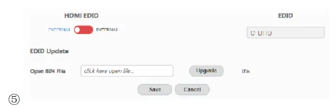
HDMI EDID: When set to Internal, the EDID communicated to the source is the one stored in the device’ s internal memory.
EDID: The name of the current EDID.
EDID Update: Upload a bin file to change what EDID is stored in the device’s internal memory that is used when EDID is set to internal.
SYSTEM page
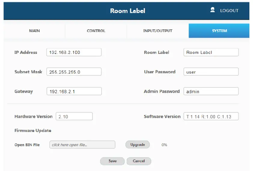
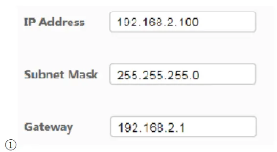
The network settings of the device’ s internal system.
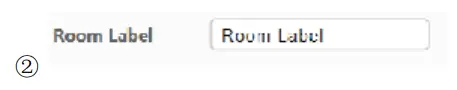
Room Label: This is the user-assigned label that appears at the top of the web interface.
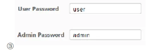
The user and the admin password settings
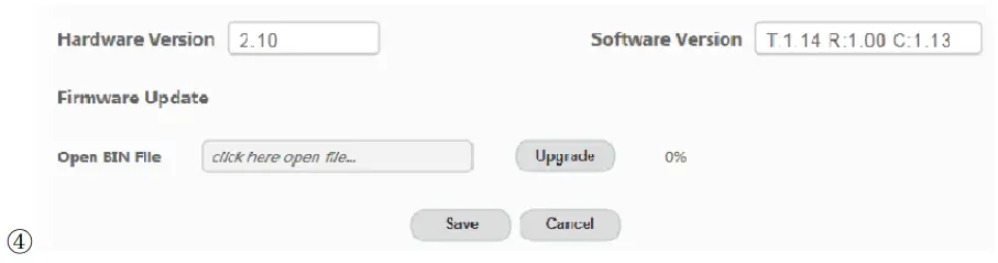
Upload new firmware versions and see the current ones install. This can update the firmware of the control panel and the receiver box, not the two-gang transmitter. To update the firmware of the two-gang switcher, use the USB port on the plate.
Note: The default ‘Username’ and ‘Password’ for the user are both ‘user.’ The user login limits the number of functions accessible.
You can click the ‘Login’ button to enter the Web GUI function Page, when you set it over The page, likes below:
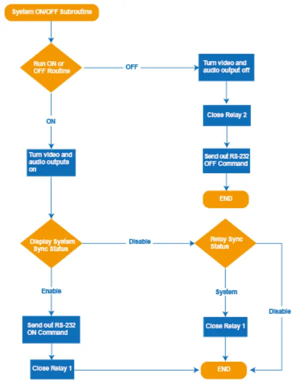
System ON/OFF Subroutine
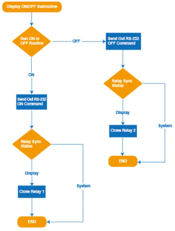
Display ON/OFF Subroutine
System Reset
To perform a system reset, hold the source button (SOURCE button) for 20 seconds until the HDCP light flashes three times. When the system is reset, user settings will return to their default values, including passwords, room labels, switching mode, IP address, etc.
Application Example