![]() VLVW-MX24P
VLVW-MX24P
2X4 HDMI 2.0 Videowall processor 18Gbps  User Manual
VER 1.02
VLVW-MX24P 2X4 HDMI 2.0 Video Wall Processor 18Gbps
Thank you for purchasing this product
Please read these instructions carefully for optimum performance and safety before connecting, operating, or adjusting this product. Please keep this manual for future reference.
A surge protection device recommended
This product contains sensitive electrical components that electrical spikes may damage, surges, electric shocks, lightning strikes, etc. The use of surge protection systems is highly recommended to protect and extend the life of your equipment.
Introduction
This product is an HDMI 2.0 Video Wall controller with 2 HDMI input, 2 HDMI loop out, and 4 HDMI scaling out for video wall processing. The Toslink jack terminal provides analog L/R audio and digital SPDIF audio output. 5-pin Phoenix jacket provides balanced L/R audio output, with PC Tool or RS232 commands to control the product for different wall displays.
Features
☆ HDMI 2.0 and HDCP 2.2 compliant
☆ Supports multi-resolution up to 3840×2160@60Hz video output for video wall
☆ Supports 2 channels HDMI loop out
☆ Supports Bezel Compensation with two modes
☆ Supports 180º rotation
☆ Supports PIP on a video wall
☆ Supports RS-232 and TCP/IP control
☆ Supports CEC control with displayer by PC Tool or commands
Package Contents
① 1 x Ultra HD Video Wall Processor
② 1 x 12V/3A Power Adapter
③ 1 x 5-pin Phoenix Connector
④ 2 x 3-pin Phoenix Connector
⑤ 1× RS232 to Phoenix Cable
⑥ 1× CAT6 cable
⑦ 1× USB to RS232 Cable
⑧ 1× User Manual
Specifications
| Technical | ||
| HDMI Compliance | HDMI 2.0 | |
| HDCP Compliance | HDCP 2.2/1.4 | |
| RS-232 | Baud rate: 57600, Data bit: 8, Stop bit: 1, no parity | |
| Input Video Formats | 4096x2160p 24/25/30/50/60Hz 3840x2160p 24/25/30/50/60Hz 1080p 24/25/30/50/60Hz 1080i 50/60Hz 1920×1200 60Hz 1680×1050 60Hz 1600×1200 60Hz 1440×900 60Hz | 1400×1050 60Hz 1366×768 60Hz 1360×768 60Hz 1280×1024 60Hz 1280×960 60Hz 1280×800 60Hz 1024x76860Hz 1280x720p50/60Hz |
| Audio Format | 2.0 channel, 5.1 channel, LPCM, Dolby, AC3, DTS | |
| ESD Protection | Human-body Model: t8kV (Air-gap discharge) , ±4kV (Contact discharge) | |
| Mechanical | ||
| Housing | Metal Enclosure | |
| Color | Black | |
| Dimensions | 218mm (W)x146mm (D)x43rnm (H) | |
| Weight | 2Kg | |
| Supply Voltage | +12V/3A | |
| Power Consumption | 25W (Max) | |
| Operating Temperature | 0°C ∼ 40°C / 32°F ∼104°F | |
| Storage Temperature | -20°C ∼ 70°C / -4°F ∼158°F | |
| Relative Humidity | 10%-50% RH (Non-Condensation) | |
Operation Controls and Functions
Front Panel
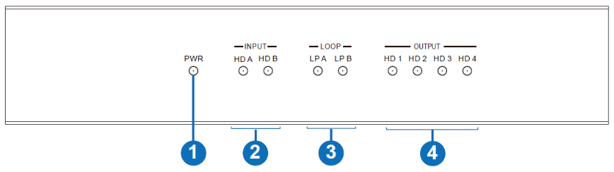
| No. | Name | Function Description |
| 1 | Power LED | The power LED will be on when the unit is powered on. |
| 2 | INPUT LED | The LED will be on when the corresponding HDMI input port is connected to an active HDMI source device. |
| 3 | LOOP LED | The LED will be on when the corresponding LOOP OUT port is connected to the HDMI display device. |
| 4 | OUTPUT LED | The LED will be on when the corresponding HDMI output port is connected to the HDMI display device. |
Rear Panel 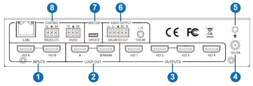
| No. | Name | Function Description |
| 1 | INPUTS | HDMI signal input ports connect to HDMI source devices such as DVD or PS4 with HDMI cable. |
| 2 | LOOP OUT | HDMI signal loops out ports. Loop out HDMI A/B signal downstream. |
| 3 | OUTPUTS | HDMI signal scaling output for video wall. |
| 4 | 12V/3A | DC 12V/3A power supply port. |
| 5 | GND | Ground the product housing. |
| 6 | AUDIO OUTPUT | TOSLINK: • Analog L/R audio output 3.5mm Stereo Jack. 20Hz ~ 20kHz, 1.5Vrms max • Digital SPDIF audio output |
| BALANCED OUT: Balanced audio output port. 5-pin phoenix connector, 20Hz ~ 20kHz, 1.5Vrms max. | ||
| 7 | SERVICE | Firmware update port. |
| 8 | CONTROL | RS232: Loop out the RS232-CTL control command. |
| RS232-CTL: External RS232 control, Baud Rate: 57600 Data Bits:8, Parity: None Stop Bits:1 | ||
| LAN: Network port for TCP/IP control. Connect to an active Ethernet link with an RJ45 cable. |
RS232/LAN Control Connection
6.1 RS232 Control Connection
The product supports RS232 control. Connect the RS232-CTL port of the product to a PC via a serial cable, as shown in the following figure: 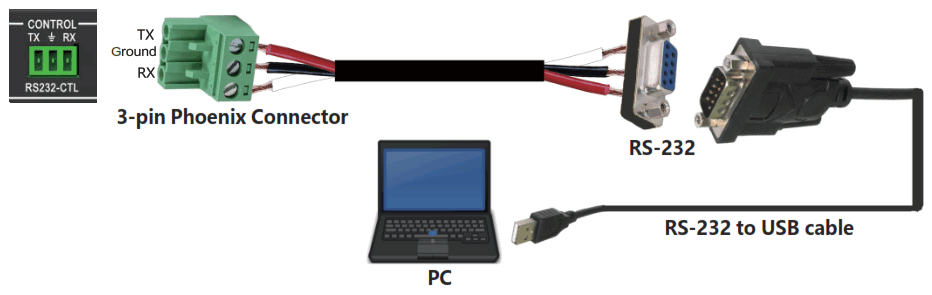
6.2 Network Control Connection
The product also supports Network control. Connect the LAN port of the product to a PC via a UTP cable, as shown in the following figure: 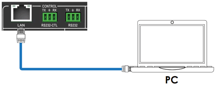
PC Tool User Guide
The PC tool is an installation-free control software that supports both UART and network control. It consists of five parts: Matrix Switch, Signal Setting, FineTune: PQ, Video Wall, and CEC Control. The UI is as follows: 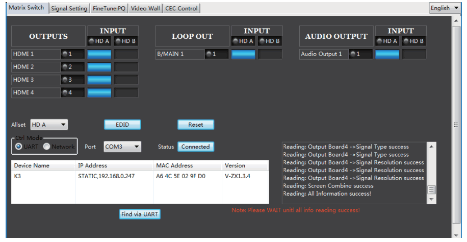
■ Matrix Switch Page
- You can select UART (with RS232 cable) or Network to connect the device; the baud rate is 57600 bps.
- Select the input source for each scaling output port.
- “AllSet” function: Select HD A or B input source to all the scaling output.
- Select the input source for the B/MAIN output port.
- Select the audio source for balanced audio output and Mini Toslink output.
- Reset: The PC tool supports a reset system to recover factory configuration.
- EDID Control: Click the “EDID” button on the Matrix Switch page, and there will be a pop-up EDID control window.
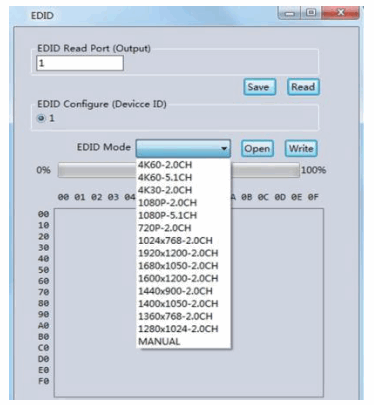
a) Read each scaling output port downstream EDID and save it as a BIN file.
b) Open an existing EDID file and write to the HDMI A and B input port as Manual EDID.
c) Select predefined EDID and write to HDMI A and B input ports.
Predefined EDID option like below:
| 4K60-2.0CH | 1920×1200-2.0CH |
| 4K60-5.1CH | 1680×1050-2.0CH |
| 4K30-2.0CH | 1600×1200-2.0CH |
| 4K30-5.1CH | 1440×900-2.0CH |
| 1080P-2.0CH | 1400×1050-2.0CH |
| 1080P-5.1CH | 1360×768-2.0CH |
| 720P-2.0CH | 1280×1024-2.0CH |
| 1024×768-2.0CH | Manual |
■ Signal Setting Page
Users can read the resolution of each input port and set the resolution of each scaling output. 
Available output resolutions:
| No. | Output Resolution Setting | No. | Output Resolution Setting |
| 1 | 3840x2160p 60Hz | 9 | 1440×1050 60Hz |
| 2 | 3840x2160p 50Hz | 10 | 1366×768 60Hz |
| 3 | 3840x2160p 30Hz | 11 | 1360×768 60Hz |
| 4 | 3840x2160p 25Hz | 12 | 1280×1024 60Hz |
| 5 | 1920×1200 60Hz | 13 | 1280×768 60Hz |
| 6 | 1920x1080p 60Hz | 14 | 1280x720p 60Hz |
| 7 | 1920x1080p 50Hz | 15 | 1280x720p 50Hz |
| 8 | 1600×1200 60Hz | 16 | 1024×768 60Hz |
Note: 3840×2160 25/30Hz can only be used for standalone display, not video wall.
■ FineTune: PQ Page
You can read and set each output’s Brightness/Contrast/Saturation/Sharpness. 
Note: Suggest always use the default setting 50/50/50/50. Do not change the default settings without special conditions; If there is a problem after changing, click “Reset” to return to the factory settings.
■ CEC Control Page 
If Auto Power On is enabled, whenever the product is turned on, it will turn on all displayers connected to it.
The product supports CEC functions, including Power on/off, Volume+/-, and Mute/Unmute.
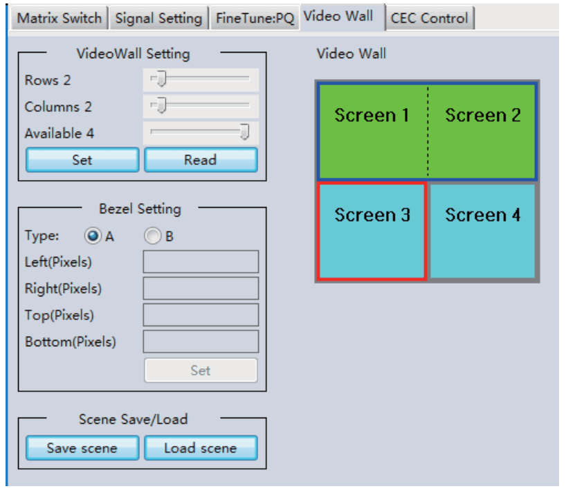
■ Video Wall Page
This page is used to configure a group of outputs to function as a video wall.
- Use the Video Wall Setting controls to change how the displays are arranged on the Video Wall page:
a. Adjust the Rows and Columns sliders to change the displayed screen arrangement to permit proper Drag-and-Select of the desired screens for the video wall.
b. Change the Available slider to set how many outputs will be used for the Video Wall.
c. Click the “Set” button to change the Screen configuration. - Use the left mouse button to drag-select the screens set for video wall mode. The selected screens will be shown as bright blue.
- Use the right mouse button to open a menu.
- Select “Screen Stitching” from the menu to program the video wall mode. The selected screens will now be shown as bright green.
- To change the displayed image: right-click to open the pop-up menu and select the desired input from the “Input Select” menu option.
- Repeating steps 2 ~ 5 above with different outputs allows for creating a second video wall.
However, changing the Rows, Columns, and Available sliders will automatically delete the current video wall set up when the “Set” button is clicked. The following example shows a more unusual video wall set-up of two video walls with two 2×1 configurations:
Video Wall Context Menu
Right-clicking on any of the screen icons will display the following context menu: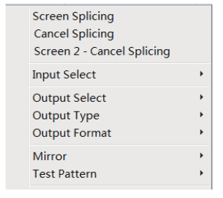
| Screen Stitching | This option connects the selected screens into a video wall configuration. |
| Cancel Stitching | Return the Video Wall configuration to normal outputs. |
| Screen x – Cancel Stitching | Remove the single screen x from the video wall to allow the displaying of another full-frame image within the video wall configuration, as shown in this example: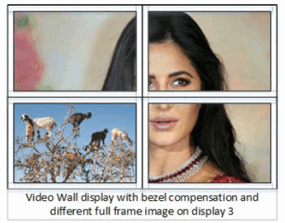 |
| Input Select | Use the sub-menu to select the input to display on the video wall or the second input image shown in the above example. |
| Output Select | This option is only available for any screen not assigned to avideo wall mode. |
| Output Type | This option is only available for any screen not assigned to avideo wall mode. |
| Output Format | This option is only available for any screen not assigned to a videowall mode. It allows the setting of the output resolution for the selected screen output. |
| Mirror | Two sub-options: OFF ( default ), ON ( H+V Mirror) When you select “ON,” you can make a 180º rotation with the selected screen. |
| Test Pattern | The output will display the Color Bar pattern when Test Pattern is enabled. |
Bezel Setting
The Bezel Setting section allows the entry of values to compensate for the display bezel thickness. These values may be entered as pixels (Type A) or millimeters (Type B). Type A
Bezel Settings
The image size will be adjusted to allow for the number of pixels entered in each entry box. Click the “Set” button to view the effect of the new values.
Type B Bezel Settings
The image size will be adjusted to allow for the Inner and Outer display dimensions in each entry box. Click the “Set” button to view the effect of the new values.
Bezel Compensation
The following images demonstrate the effect of not having bezel compensation and what correctly configured bezel compensation settings should produce: 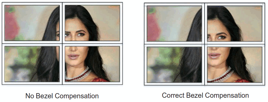
Layout Save/Load
The Save Scene/Layout and Load Scene/Layout buttons allow a video wall configuration to be saved or recalled at any time. Up to 10 configurations, each with its name, can be saved or recalled. Each Scene can optionally be given a name to identify that video wall scene setup when saving.
Safety Instructions
To ensure this product’s reliable operation and protect the safety of any person using or handling this device while powered, please observe the following instructions.
- Do not operate either of these products outside the specified temperature and humidity range given in the above specifications.
- Ensure there is adequate ventilation to allow this product to operate efficiently.
- Qualified professionals should only repair the equipment as these products contain sensitive devices that any mistreatment may damage.
- Only use this product in a dry environment. Do not allow any liquids or harmful chemicals to come into contact with these products.
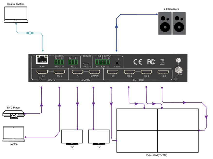
Connection Diagram
![]()


