VigilLinke VLWP-3HVG-CTR Control Wall Panel for HBT-WPB200U User Manual
Thank you for purchasing this product
Please read these instructions carefully for optimum performance and safety before connecting, operating, or adjusting this product. Please keep this manual for future reference.
A surge protection device is recommended.
This product contains sensitive electrical components that electrical spikes may damage surges, electric shocks, lightning strikes, etc. Use of surge protection systems are highly recommended to protect and extend the life of your equipment.
Introduction
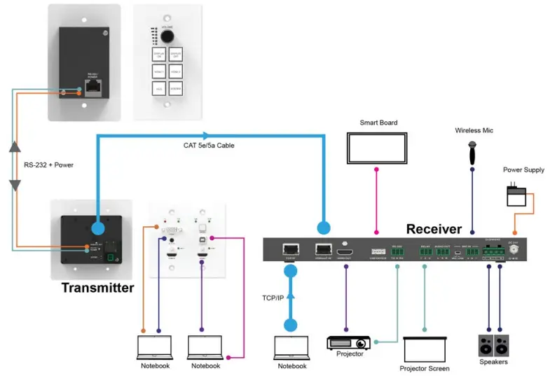
The control panel supports volume control, video switching, and system control. At the same time, it supports 2 HDMI and one VGA input selection. The RS-232 port on the transmitter connects and provides a power supply to the RS-232 port on the control panel via CAT5e/6/7 cable.
Features
- Supports volume control, video switching, and system control
- RS-232 port connects between the control panel and transmitter via CAT5e/6/7 cable
- Supports transmitter power supply to control panel
Package Contents
- 1 x Control Panel
- 1 x User Manual
Specifications
| Mechanical | ||
| Housing | Metal Enclosure | |
| Color | White — Front Panel, Black — Rear Panel | |
| Dimensions | 114.3mm [W] x 69.9mm [D] x 22.2mm [H] | |
| Weight | 180g | |
| Operating Temperature | 32 – 104°F / 0 – 40°C | |
| Storage Temperature | -4 – 140°F / -20 – 60°C | |
| Relative Humidity | 20 – 90% RH (no condensation) | |
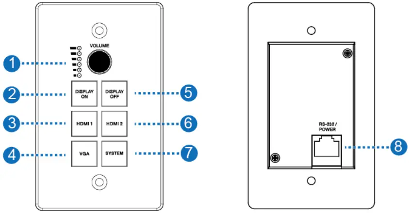
Operation Controls and Functions
| Number | Name | Function description |
| 1 | VOLUME Knob and Volume level indicator | Adjust amplifier volume output. ▪ Clockwise adjustment to increase the volume. ▪ Counter-clockwise adjustment to decrease the volume. |
| 2 | DISPLAY ON | Run Display ON Subroutine; see section 7. Press and hold the button to close relay 1. |
| 3 | HDMI 1 | Select HDMI 1 signal as the input source. |
| 4 | VGA | Select the VGA signal as the input source. |
| 5 | DISPLAY OFF | Run Display OFF Subroutine; see section 7. Press and hold the button to close relay 2. |
| 6 | HDMI 2 | Select HDMI 2 signal as the input source. |
| 7 | SYSTEM | Long-press the button for 3 seconds to open or close the system, see section 6. |
| 8 | RS-232/POWER | Connect to Transmitter via CAT5e/6/7 cable. |
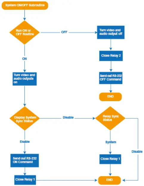
System ON/OFF Subroutine
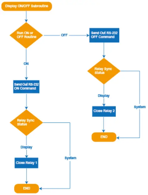
Display ON/OFF Subroutine
Application Example