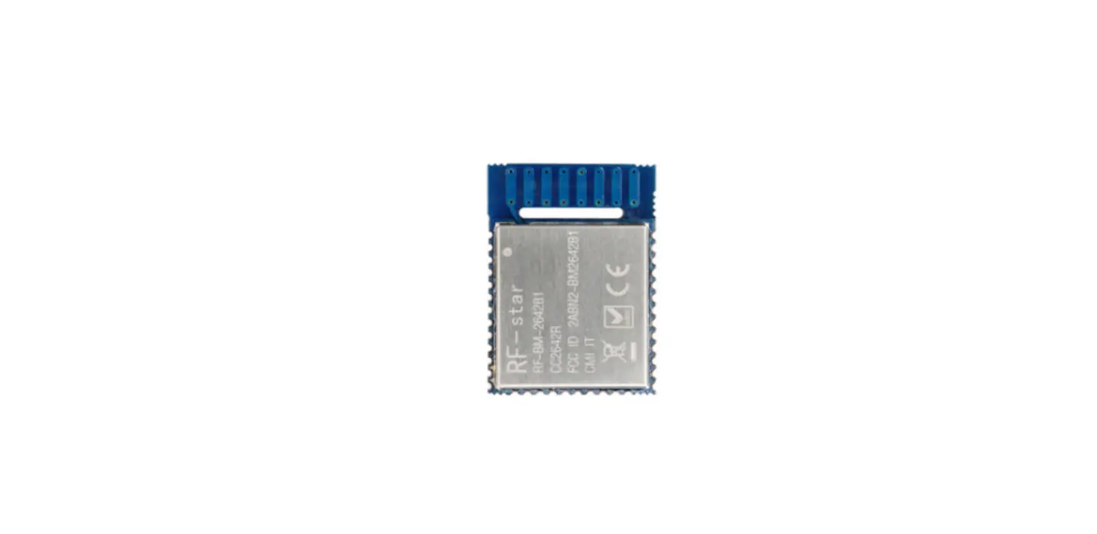
RF-star RF-BM-2642B1 SimpleLink Bluetooth 5 Low Energy Wireless Module

TI CC264X BLE Module List
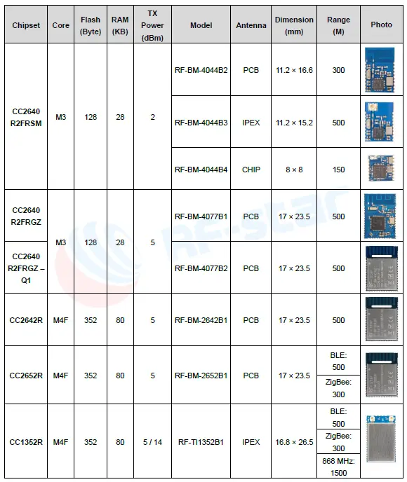
Note:
- The communication distance is the longest distance obtained by testing the module’s maximum transmission power in an open and interference-free environment in sunny weather.
- Click the picture to buy modules.
Device Overview
Description
RF-BM-2642B1 is an RF module based on TI lower-power CC2642R SoC. It integrates a 48 MHz crystal and a 32.768 kHz crystal, 352 KB of in-system Programmable Flash, 256 KB ROM, 8 KB of cache SRAM, 80 KB of ultra-low leakage SRAM. Its ARM® Cortex®-M4F core application processor can operate at an extremely low current at flexible power modes. Its 2.4 GHz RF transceiver is compatible with Bluetooth 5 Low Energy. It features a small size, robust connection distance, and rigid reliability.
Key Features
- RF Section
- 2.4GHz RF transceiver compatible with Bluetooth 5 Low Energy
- Excellent receiver sensitivity
- 105 dBm for BLE 125 kbps (LE coded PHY)
- 97 dBm for 1 Mbps PHY
- Output power up to +5 dBm with temperature compensation
- Suitable for systems targeting compliance with worldwide radio frequency regulations
- Microcontroller
- Powerful 48 MHz ARM® Cortex®-M4F processor
- EEBMC CoreMark® score: 148
- 352 KB of in-system programmable flash
- 256 KB of ROM for protocols and library functions
- KB of cache SRAM
- 80 KB of ultra-low leakage SRAM
- Support OTA upgrade
- Ultra-low-power sensor controller with 4 KB of SRAM
- Sample, store, and process sensor data
- Operation independent from system CPU
- Fast wake-up for low-power operation
- Peripherals
- Digital peripheral pins can be routed to 31 GPIOs
- 4 × 32-bit or 8 × 16-bit general-purpose timers
- 12-bit ADC, 200 ksamples/s, 8 channels
- 2 × comparators with internal reference DAC
- Ultra-low-power analog comparator
- Programmable current source
- 2 × UART
- 2 × SSI (SPI, Microwave, TI)
- I2C
- I2S
- Real-time clock (RTC)
- AES 128 and 256 bit Crypto accelerator
- ECC and RSA public key hardware accelerator
- SHA2 accelerator (full suite up to SHA-512)
- True random number generator (TRNG)
- Capacitive sensing, up to 8 channels
- Integrated temperature and battery monitor
- External system
- On-chip buck DC/DC converter
- Low Power
- Wide supply voltage range: 1.8 V ~ 3.8 V
- Active-mode RX: 6.9 mA
- Active-mode TX at 0 dBm: 7.3 mA
- Active-mode TX at +5 dBm: 9.6 mA
- Active-mode MCU 48 MHz (CoreMark): 3.4 mA (71 μA/MHz)
- Sensor controller, low power-mode, 2 MHz, running infinite loop: 30.8 μA
- Sensor controller, active-mode, 24 MHz, running infinite loop: 808 μA
- – Standby: 0.94 µA (RTC on, 80 KB RAM and CPU retention)
- – Shutdown: 150 nA (wakeup on external events)
Applications
- Personal electronics
- Mobile phone accessories
- Sports and fitness equipment
- HID applications
- Smart grid and automatic meter reading
- Wireless sensor networks
- Active RFID
- Energy harvesting applications
- Electronic Shelf Label (ESL)
- Home and building automation
- Wireless alarm and security systems
- Long-range sensor applications
Functional Block Diagram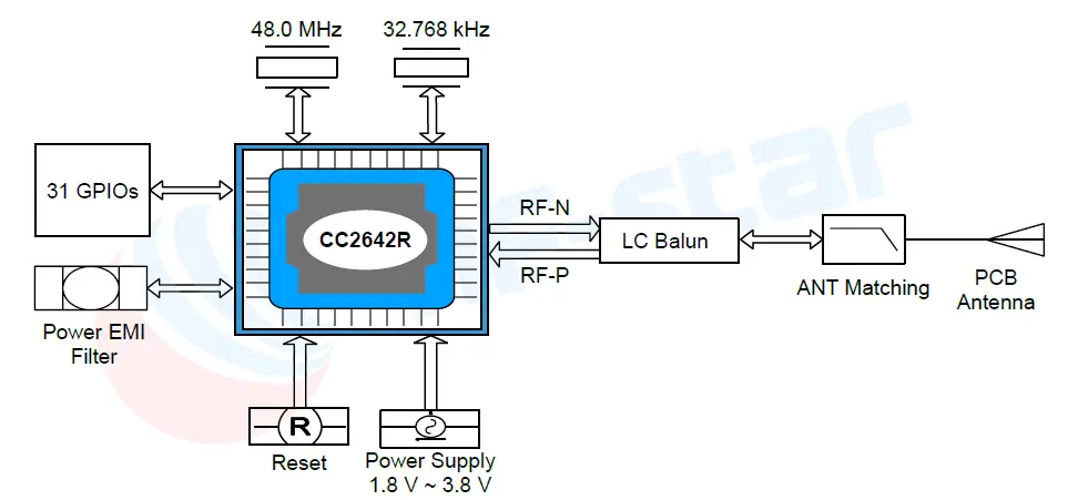
Part Number Conventions
The part numbers are of the form of RF-BM-2642B1 where the fields are defined as follows: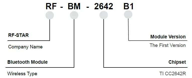
Module Configuration and Functions
Module Parameters
| Chipset | CC2642R |
| Supply Power Voltage | 1.8 V ~ 3.8 V, recommended to 3.3 V |
| Frequency | 2402 MHz ~ 2480 MHz |
| Maximum Transmit Power | +5.0 dBm |
| Receiving Sensitivity | -97 dBm |
| GPIO | 31 |
|
Power Consumption | RX current: 6.9 mA TX current: 7.3 mA @ 0 dBm 9.6 mA @ 5 dBm MCU 48 MHz (CoreMark):3.4 mA (71 μA/MHz) Sensor Controller:30.8 μA @ low power-mode, 2 MHz 808 μA @ active-mode, 24 MHz Standby: 0.94 µA Shutdown: 150 nA |
| Support Protocol | Bluetooth 5 Low Energy |
| Crystal | 48 MHz, 32.768 kHz |
| Package | SMT packaging (Half hole) |
| Communication Interface | UART, SPI, I2C, I2S |
| Dimension | 23.50 mm × 17.0 mm × (2.2 ± 0.1) mm |
| Type of Antenna | PCB Antenna |
| Operating Temperature | -40 ℃ ~ +85 ℃ |
| Storage Temperature | -40 ℃ ~ +125 ℃ |
Module Pin Diagram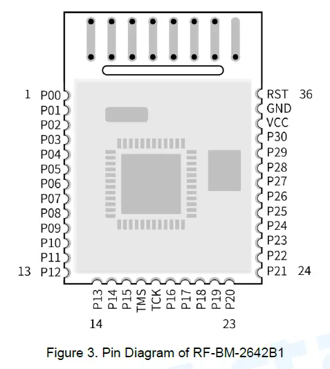
Pin Functions
| Pin | Name | Function | Description |
| 1 | P00 | GPIO | GPIO, Sensor Controller |
| 2 | P01 | GPIO | GPIO, Sensor Controller |
| 3 | P02 | GPIO | GPIO, Sensor Controller |
| 4 | P03 | GPIO | GPIO, Sensor Controller |
| 5 | P04 | GPIO | GPIO, Sensor Controller |
| 6 | P05 | GPIO | GPIO, Sensor Controller, high-drive capability |
| 7 | P06 | GPIO | GPIO, Sensor Controller, high-drive capability |
| 8 | P07 | GPIO | GPIO, Sensor Controller, high-drive capability |
| 9 | P08 | GPIO | GPIO |
| 10 | P09 | GPIO | GPIO |
| 11 | P10 | GPIO | GPIO |
| 12 | P11 | GPIO | GPIO |
| 13 | P12 | GPIO | GPIO |
| 14 | P13 | GPIO | GPIO |
| 15 | P14 | GPIO | GPIO |
| 16 | P15 | GPIO | GPIO |
| 17 | JTAG_TMSC | JTAG_TMSC | JTAG TMSC, high-drive capability |
| 18 | JTAG_TCKC | JTAG_TCKC | JTAG TCKC |
| 19 | P16 | GPIO | GPIO, JTAG_TDO, high-drive capability |
| 20 | P17 | GPIO | GPIO, JTAG_TDI, high-drive capability |
| 21 | P18 | GPIO | GPIO |
| 22 | P19 | GPIO | GPIO |
| 23 | P20 | GPIO | GPIO |
| 24 | P21 | GPIO | GPIO |
| 25 | P22 | GPIO | GPIO |
| 26 | P23 | GPIO | GPIO, Sensor Controller, Analog |
| 27 | P24 | GPIO | GPIO, Sensor Controller, Analog |
| 28 | P25 | GPIO | GPIO, Sensor Controller, Analog |
| 29 | P26 | GPIO | GPIO, Sensor Controller, Analog |
| 30 | P27 | GPIO | GPIO, Sensor Controller, Analog |
| 31 | P28 | GPIO | GPIO, Sensor Controller, Analog |
| 32 | P29 | GPIO | GPIO, Sensor Controller, Analog |
| 33 | P30 | GPIO | GPIO, Sensor Controller, Analog |
| 34 | VDD_EB | VDD | Power Supply: 1.8 V ~ 3.8 V, recommend to 3.3 V |
| 35 | GND | GND | Ground |
| 36 | NRESET | RESET_N | Reset, active-low. No internal pullup |
Specifications
Recommended Operating Conditions
The functional operation does not guarantee performance beyond the limits of the conditional parameter values in the table below. Long-term work beyond this limit will affect the reliability of the module more or less.
| Items | Condition | Min. | Typ. | Max. | Unit |
| Operating Supply Voltage | / | 1.8 | 3.3 | 3.8 | V |
| Operating Temperature | / | -40 | +25 | +85 | ℃ |
Handling Ratings
| Items | Condition | Min. | Typ. | Max. | Unit |
| Storage Temperature | Tstg | -40 | +25 | +125 | ℃ |
| Human Body Model | HBM | ±2000 | V | ||
| Moisture Sensitivity Level | 2 | ||||
| Charged Device Model | ±500 | V |
Power Consumption
Power Mode
Measured on the RF-BM-2642B1 reference design with Tc = 25°C, VDDS = 3.0 V with internal DC/DC converter, unless otherwise noted.
| Parameter | Test Conditions | Typ. | Unit | |
| Core Current Consumption | ||||
|
Icore |
Reset and Shutdown | Reset. RESET_N pin asserted or VDDS below power-on-reset threshold | 150 | nA |
| Shutdown. No clocks running, no retention | 150 | nA | ||
| Standby without cache | RTC running, CPU, 80 KB RAM and (partial) register retention. | 0.94 | μA | |
| retention | RCOSC_LF | |||
| RTC running, CPU, 80 KB RAM and (partial) register retention.
XOSC_LF | 1.09 | μA | ||
|
Standby
with cache retention | RTC running, CPU, 80 KB RAM and (partial) register retention.
RCOSC_LF | 3.2 | μA | |
| RTC running, CPU, 80 KB RAM and (partial) register retention.
XOSC_LF | 3.3 | μA | ||
| Idle | Supply Systems and RAM powered RCOSC_HF | 675 | μA | |
| Active | MCU running CoreMark at 48 MHz RCOSC_HF | 3.39 | mA | |
| Peripheral Current Consumption | ||||
|
Iperi | Peripheral power domain | Delta current with domain enabled | 97.7 | μA |
| Serial power domain | Delta current with domain enabled | 7.2 | μA | |
| RF Core | Delta current with power domain enabled, clock enabled, RF core idle | 210.9 | μA | |
| μDMA | Delta current with clock enabled, module is idle | 63.9 | μA | |
| Timer | Delta current with clock enabled, module is idle | 81.0 | μA | |
| I2C | Delta current with clock enabled, module is idle | 10.1 | μA | |
| I2S | Delta current with clock enabled, module is idle | 26.3 | μA | |
| SSI | Delta current with clock enabled, module is idle | 82.9 | μA | |
| UART | Delta current with clock enabled, module is idle | 167.5 | μA | |
| CRYPTO (AES) | Delta current with clock enabled, module is idle | 25.6 | μA | |
| PKA | Delta current with clock enabled, module is idle | 84.7 | μA | |
| TRNG | Delta current with clock enabled, module is idle | 35.6 | μA | |
| Sensor Controller Engine Consumption | ||||
| ISCE | Active mode | 24 MHz, Infinite loop | 808.5 | μA |
| Low-power mode | 2 MHz, Infinite loop | 30.1 | μA | |
Radio Mode
Measured on the RF-BM-2642B1 reference design with Tc = 25°C, VDDS = 3.0 V with internal DC/DC converter, unless otherwise noted.
| Parameter | Test Conditions | Typ. | Unit |
| Radio Receive Current | 2440 MHz | 6.9 | mA |
|
Radio Transmit Current | +5 dBm output power setting
2440 MHz | 7.3 | mA |
| +5 dBm output power setting
2440 MHz | 9.6 | mA |
Application, Implementation, and Layout
Module Photos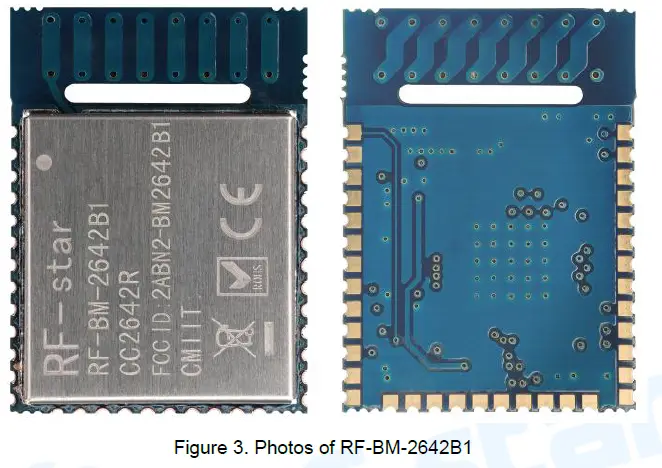
Recommended PCB Footprint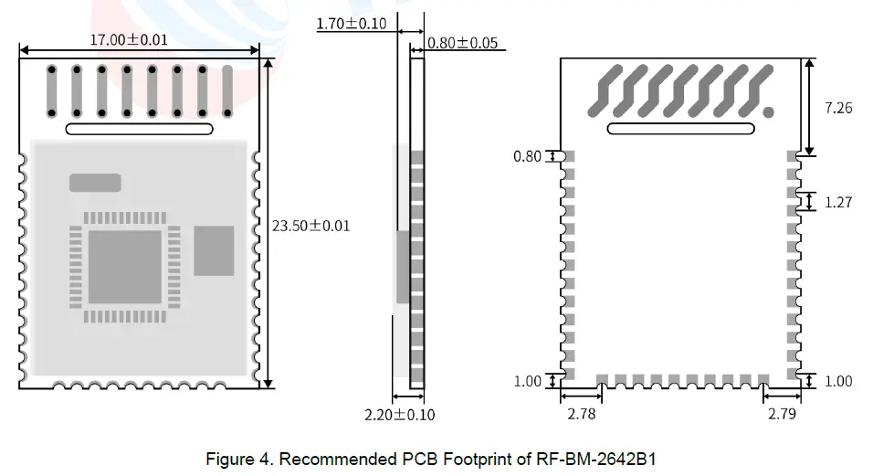
Schematic Diagram 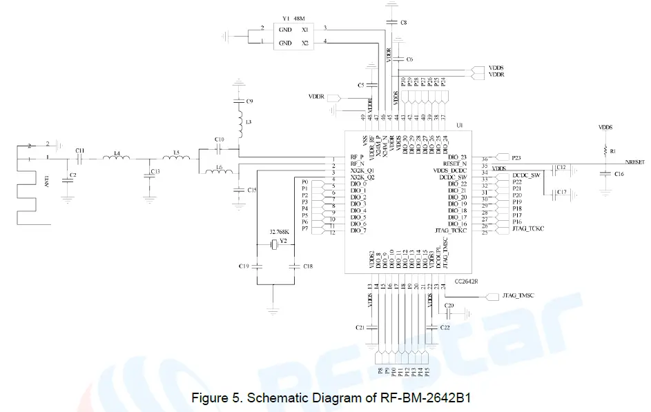
Basic Operation of Hardware Design
- It is recommended to offer the module with a DC stabilized power supply, a tiny power supply ripple coefficient, and reliable ground. Please pay attention to the correct connection between the positive and negative poles of the power supply. Otherwise, the reverse connection may cause permanent damage to the module;
- Please ensure the supply voltage is between the recommended values. The module will be permanently damaged if the voltage exceeds the maximum value. Please ensure a stable power supply and no frequently fluctuating voltage.
- When designing the power supply circuit for the module, it is recommended to reserve more than 30% of the margin, which is beneficial to the long-term stable operation of the whole machine. The module should be far away from the power electromagnetic, transformer, high-frequency wiring, and other parts with large electromagnetic interference.
- The bottom of the module should avoid high-frequency digital routing, high-frequency analog routing, and power routing. If it has to route the wire on the bottom of the module, for example, it is assumed that the module is soldered to the Top Layer, the copper must be spread on the connection part of the top layer and the module, and be close to the digital part of the module and routed in the Bottom Layer (all copper is well-grounded).
- Assuming that the module is soldered or placed in the Top Layer, it is also wrong to randomly route the Bottom Layer or other layers, which will affect the spurs and receiving sensitivity of the module to some degree;
- Assuming that there are devices with large electromagnetic interference around the module, which will greatly affect the module performance. It is recommended to stay away from the module according to the strength of the interference. If circumstances permit, appropriate isolation and shielding can be done.
- Assuming that there are routings of large electromagnetic interference around the module (high-frequency digital, high-frequency analog, power routings), which will also greatly affect the module performance. It is recommended to stay away from the module according to the strength of the interference. If circumstances permit, appropriate isolation and shielding can be done.
- It is recommended to stay away from the devices whose TTL protocol is the same 2.4 GHz physical layer, for example, USB 3.0.
- The antenna installation structure has a great influence on the module performance. It is necessary to ensure the antenna is exposed and preferably vertically upward. When the module is installed inside of the case, a high-quality antenna extension wire can be used to extend the antenna to the outside of the case.
- The antenna must not be installed inside the metal case, which will cause the transmission distance to be greatly weakened.
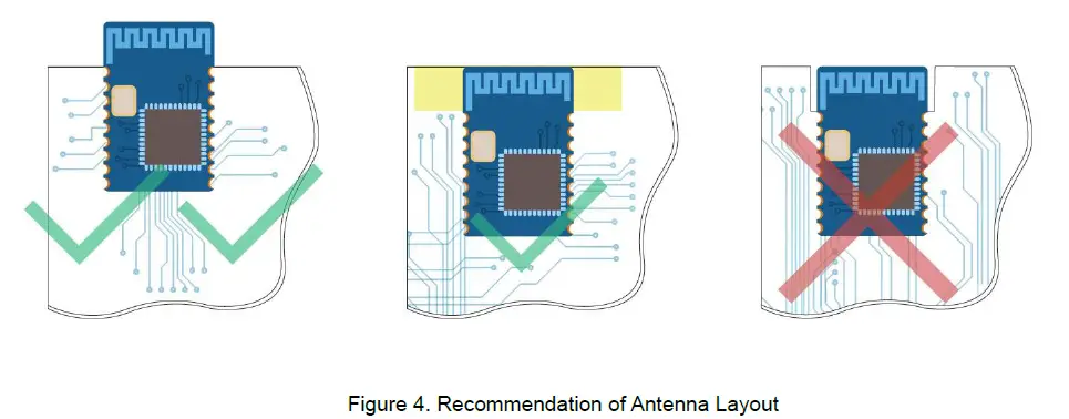
- The recommendation of antenna layout. The inverted-F antenna position on PCB is free-space electromagnetic radiation. The location and layout of the antenna is a key factor to increase the data rate and transmission range. Therefore, the layout of the module antenna location and routing is recommended as follows:
- Place the antenna on the edge (corner) of the PCB.
- Make sure that there is no signal line or copper foil in each layer below the antenna.
- It is the best to hollow out the red part of the antenna position in the following figure so as to ensure that the S11 of the module is minimally affected.

Trouble Shooting
Unsatisfactory Transmission Distance
- When there is a linear communication obstacle, the communication distance will be correspondingly weakened. Temperature, humidity, and co-channel interference will lead to an increase in the communication packet loss rate. The performances of ground absorption and reflection of radio waves will be poor when the module is tested close to the ground.
- Seawater has a strong ability to absorb radio waves, so the test results by the seaside are poor.
- The signal attenuation will be very obvious if there is a metal near the antenna or the module is placed inside of the metal shell.
- The incorrect power register set or the high data rate in an open air may shorten the communication distance. The higher the data rate, the closer the distance.
- The low voltage of the power supply is lower than the recommended value at ambient temperature, and the lower the voltage, the smaller the power is.
- The unmatchable antennas and module or the poor quality of antenna will affect the communication distance.
Vulnerable Module
- Please ensure the supply voltage is between the recommended values. The module will be permanently damaged if the voltage exceeds the maximum value. Please ensure the stable power supply and no frequently fluctuated voltage.
- Please ensure the anti-static installation and the electrostatic sensitivity of high-frequency devices.
- Due to some humidity-sensitive components, please ensure the suitable humidity during installation and application. If there is no special demand, it is not recommended to use at too high or too low a temperature.
High Bit Error Rate
- There are co-channel signal interferences nearby. It is recommended to be away from the interference sources or modify the frequency and channel to avoid interferences.
- The unsatisfactory power supply may also cause garbled. It is necessary to ensure the power supply reliability.
- If the extension wire or feeder wire is of poor quality or too long, the bit error rate will be high.
Electrostatics Discharge Warnings
The module will be damaged for the discharge of static. RF-star suggest that all modules should follow the 3 precautions below:
- According to the anti-static measures, bare hands are not allowed to touch modules.
- Modules must be placed in anti- static areas.
- Take the anti-static circuitry (when inputting HV or VHF) into consideration in product design. Static may result in the degradation in performance of module, even causing the failure.
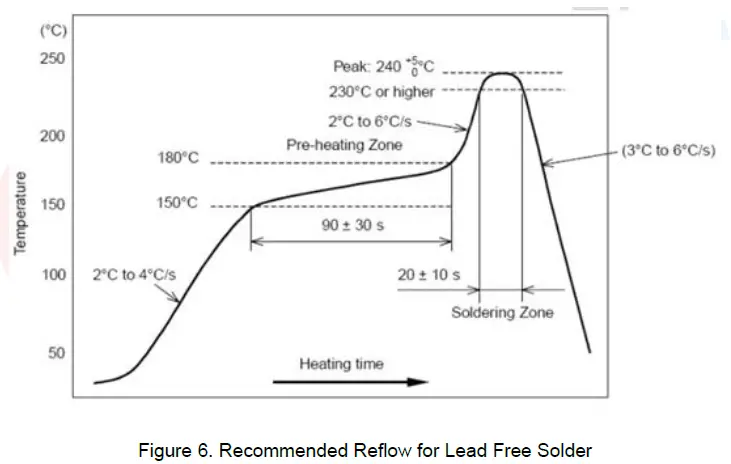
Soldering and Reflow Condition
- Heating method: Conventional Convection or IR/convection.
- Temperature measurement: Thermocouple d = 0.1 mm to 0.2 mm CA (K) or CC (T) at soldering portion or equivalent methods.
- Solder paste composition: Sn/3.0 Ag/0.5 Cu
- Allowable reflow soldering times: 2 times based on the following reflow soldering profile.
- Temperature profile: Reflow soldering shall be done according to the following temperature profile.
- Peak temperature: 245 ℃.

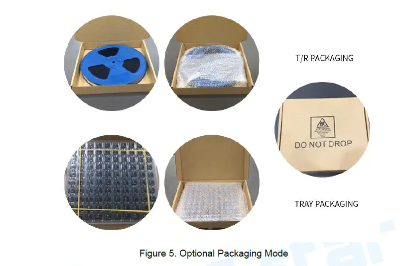
Optional Packaging
Revision History
| Date | Version No. | Description | Author |
| 2019.09.11 | V1.0 | The initial version is released. | Aroo Wang |
| 2020.01.19 | V1.0 | Add TI CC264X BLE module list. | Sunny Li |
Contact Us
SHENZHEN RF-STAR TECHNOLOGY CO., LTD.
- Shenzhen HQ:
- Add.: Room 601, Block C, Skyworth Building, High-tech Park, Nanshan District, Shenzhen, Guangdong, China Tel.: 86-755-3695 3756
- Chengdu Branch:
- Add.: No. B4-12, Building No.1, No. 1480 Tianfu Road North Section (Incubation Park), High-Tech Zone, Chengdu, China (Sichuan) Free Trade Zone, 610000
- Tel.: 86-28-6577 5970
- Email: [email protected], [email protected]
- Web.: www.szrfstar.com
FCC Statement
This device complies with part 15 of the FCC Rules. Operation is subject to the following two conditions: (1) This device may not cause harmful interference, and (2) this device must accept any interference received, including interference that may cause undesired operation. Any changes or modifications not expressly approved by the party responsible for compliance could void the user’s authority to operate the equipment.
Note: This equipment has been tested and found to comply with the limits for a Class B digital device, pursuant to part 15 of the FCC Rules. These limits are designed to provide reasonable protection against harmful interference in a residential installation. This equipment generates, uses and can radiate radio frequency energy and, if not installed and used in accordance with the instructions, may cause harmful interference to radio communications. However, there is no guarantee that interference will not occur in a particular installation. If this equipment does cause harmful interference to radio or television reception, which can be determined by turning the equipment off and on, the user is encouraged to try to correct the interference by one or more of the following measures:
- Reorient or relocate the receiving antenna.
- Increase the separation between the equipment and receiver.
- Connect the equipment into an outlet on a circuit different from that to which the receiver is connected.
- Consult the dealer or an experienced radio/TV technician for help.
FCC Radiation Exposure Statement
This modular complies with FCC RF radiation exposure limits set forth for an uncontrolled environment. This transmitter must not be co-located or operating in conjunction with any other antenna or transmitter.
References
 蓝牙模块,LoRaMesh,ZigBee,BLE,iBeacon,蓝牙方案源头供应商,蓝牙模组-信驰达科技
-
蓝牙模块,LoRaMesh,ZigBee,BLE,iBeacon,蓝牙方案源头供应商,蓝牙模组-信驰达科技
 Source CC2640R2F BLE module CC2640 BLE Module IoT module CC2640R2F on m.alibaba.com
-
Source cc2652 CC2652R ZigBee2MQTT module Multiprotocol 2.4 GHz Wireless Module BLE 5 module and IEEE 802.15.4 PHY and MAC on m.alibaba.com
-
Wholesale ble CC2642R CC2642 Long distance CC2642 low power cheap BT5.0 BLE module ble CC2642R CC2642 From m.alibaba.com
-
Wholesale Low-power Sub-1G 868mhz 920mhz 2.4 G Dual-band Multi-protocol CC1352 Module From m.alibaba.com
-
Wholesale BLE CC2640 module 100m BLE 4.2 TI CC2640R2F module BLE CC2640 From m.alibaba.com
-
Source CC2640R2F Industry temperature BLE 5.0 TI CC2640R2F-Q1 module for automotive BLE CC2640 CC2640R2F on m.alibaba.com
-
Source CC2640 Tiny BLE module BLE4.2 CC2640R2F Module CC2640 GPIO on m.alibaba.com


