Wireless Tag WT5105-M1 Bluetooth Module

Disclaimer and copyright notice
The information in this article, including the URL for reference, is subject to change without notice. The document is provided “as is” without warranty of any kind, including any warranty of merchantability, fitness for a particular purpose or non-infringement, and any warranty of any proposal, specification or sample referred to elsewhere. This document shall not be hiable, including any infringement of any patent right resulting from the use of the information contained in this document. No estoppel or other license, express or implied, is granted herein for the use of intellectual property. The Bluetooth alliance member logo belongs to the Bluetooth Alliance. It is hereby declared that all trade names, trade marks and registered trade marks mentioned herein are the property of their respective owners.
| Historic version | |||||||||||
| Version | Author | Date | Describe | ||||||||
| 1.0.0 | Brussin,LIYAN | 2020-3-25 | First creation | ||||||||
| 1.0.1 | Brussin | 2020-3-25 | Add GPIO14,15,20 indicator function description | ||||||||
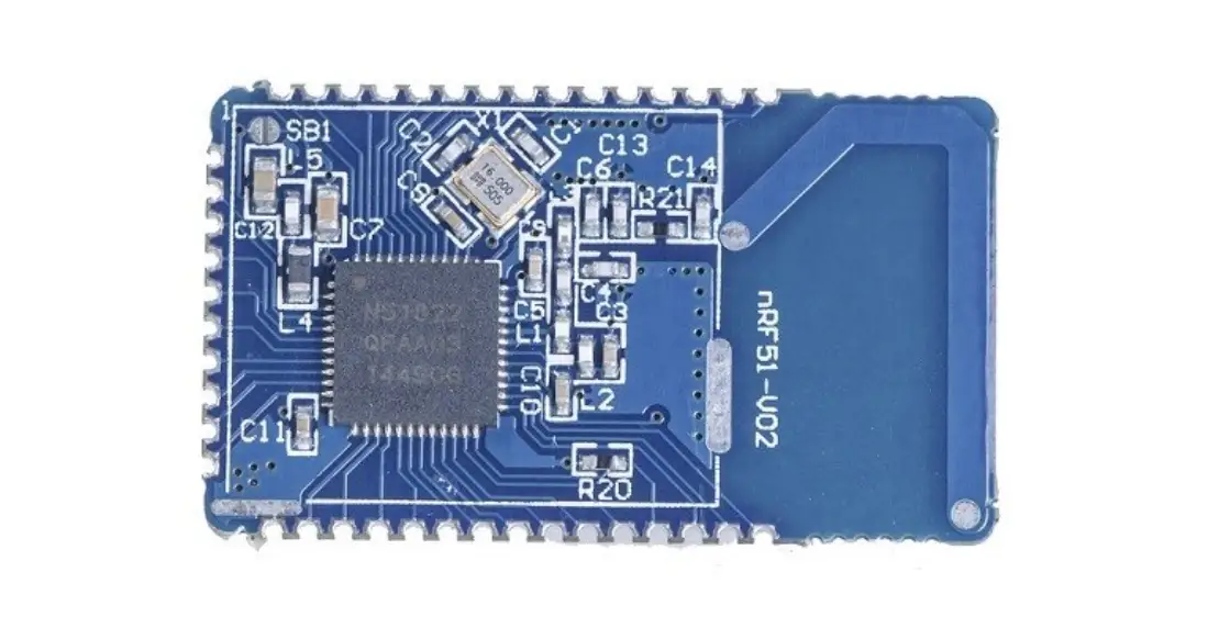
Overview of the main chip WT5105
The WT51XX series is a high-performance Bluetooth system-on-chip (SoC) launched by The wireless-tag company. It supports Bluetooth 5.0 and can be widely used in mobile devices, wearable products, and Internet of Things (IoT) products. This series of chips can help users develop Bluetooth low energy application products with central and/or peripheral roles.
- ARM® Cortex®-M0 32-bit microprocessor
- Storage
- 512KB/2MB system flash memory, 128KB ROM, 138KB SRAM, all data is kept constant in sleep mode, 8-channel DMA
- 33/19 general purpose I/O pins 3 QDEC decoders, 6 channel PWM, 4 channel I2S, 2 channel PDM, 2 channel I2C, 2 channel SPI, 1 channel UART JTAG
- Support DMIC/AMIC microphone function
- 8-channel 12-bit ADC supporting low-noise PGA
- 4-channel 24-bit clock, 1 monitoring clock, real-time counter (RTC)
- Power management (1.8-3.6V)Embedded LDOs, embedded step-down DC-DC, supply voltage range (1.8- 3.6V)
Power monitor: support low battery detection
- Power consumption
- Sleep mode, only wake up through IO, current amount is 0.8uA
- Sleep mode, wake up by RTC, current amount 7uA
- Peak system current in RX mode 6.7mA
- Peak system current 6.7mA at TX 0dBm transmit power
- RC oscillator hardware calibration
- 32KHz RC RTC oscillator automatic calibration, accuracy is +/-500ppm 32MHz RC HCLK oscillator automatic calibration, accuracy is 3%
- High rate throughput
- Support BLE 2Mbps protocol
- Support data length extension (DLE) function
- Support SIG-Mesh
- 2.4G transceiver
- Support BLE5.0
- RFPHY1Mbps/2Mbps/500Kbps/125Kbps
- Receive sensitivity:
- BLE1Mbps data rate: -97dBm
- BLE125Kbps data rate: -103dBm
- Transmit power: -20dBm to 10dBm, 3dBm step
- Single-pin antenna: no RF matching or RX/TX switching
- RSSI: 1dB resolution
- AES-128 hardware encryption
- Working temperature: -40℃~125℃
- RoHS Footprint: QFN48/QFN32
Module Characteristice
- Onboard PCB antenna
- Working voltage: 3.3V
- Working environment temperature: -20-85°C
- System
- Support Bluetooth 5.0
Ultra-small size module 16.0mm*13.0mm*3mm (±0.2mm)
Low-power sleep mode: 3µA, can be woken up by wake-up IO (P14)
The module supports AT command of UART serial port and two-way data transparent transmission with Bluetooth host by default
Hardware Specifications
System Block Diagram
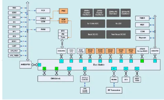
Chart 1 system block diagram
Pin Description
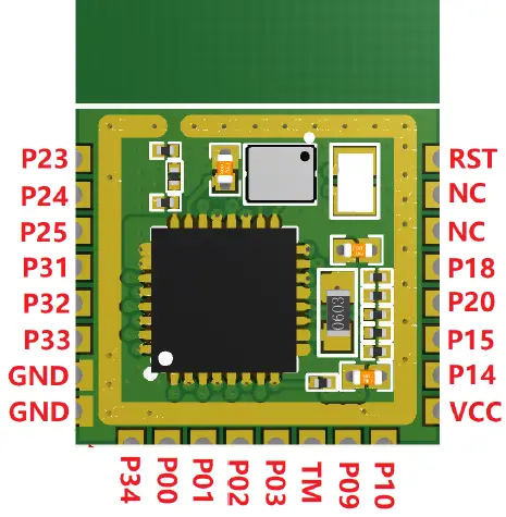
Figure 2 Product Pin Diagram
| PIN | NAME | Description |
| 1 | P23 | GPIO23 |
| 2 | P24 | GPIO24 |
| 3 | P25 | GPIO25 |
| 4 | P31 | GPIO31 |
| 5 | P32 | GPIO32 |
| 6 | P33 | GPIO33 |
| 7 | GND | GND |
| 8 | GND | GND |
| 9 | P34 | GPIO34 |
| 10 | P00 | GPIO00 |
| 11 | P01 | GPIO01 |
| 12 | P02 | GPIO02 |
| 13 | P03 | GPIO03 |
| 14 | TM | TestMode/ISP download mode and Flash operation mode control pins |
| 15 | P09 | GPIO09,TX |
| 16 | P10 | GPIO10,RX |
| 17 | VCC | Power input 1.8V-3.6V |
| 18 | P14 | GPIO14,Sleep wake up pin, high level wake up |
| 19 | P15 | GPIO15,Mode indicator pin, high level working mode, low level sleep mode |
| 20 | P20 | GPIO20,Bluetooth connection status indication, high level connection, low level disconnection |
| 21 | P18 | GPIO18 |
| 22 | NC | NC |
| 23 | NC | NC |
| 24 | RST | Chip reset pin |
Electrical Characteristics
Maximum rating
Figure 4 Maximum ratings
| Rated value | condition | value | unit |
| Storage temperature | / | -40 to 85 | °C |
| MAX Welding temperature | / | 260 | °C |
| Supply voltage | IPC/JEDEC J-STD- 020 | +1.8 to +3.6 | V |
Figure 5 Recommended working environment
| working environment | NAME | MIN | TYPE | MAX | UNIT |
| Operating temperature | / | -20 | 20 | 85 | °C |
| Supply voltage | VDD | 2.7 | 3.3 | 3.6 | V |
Power Consumption
Figure 6 Power consumption description
| Mode | Transmit power | Rate | Type | Unit |
| Sleep | 3 | µA | ||
| Tx | 0db | 1Mbps | 3.05 | mA |
| Rx | All rates | 3.9 | mA | |
Application Notes
Module Size
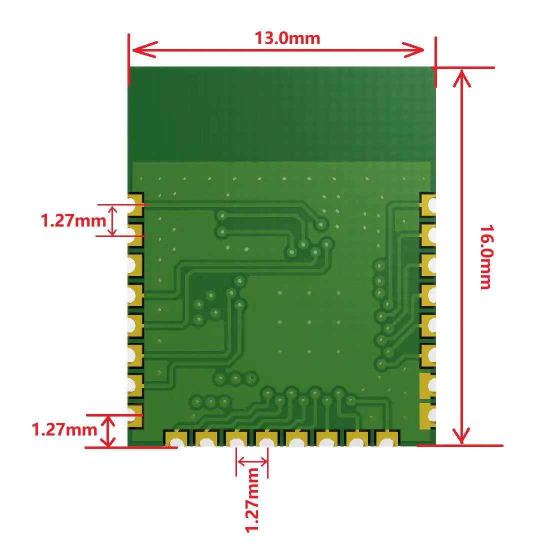
Figure 7 Module dimensions (bottom view)
Reelow Soldering Curve
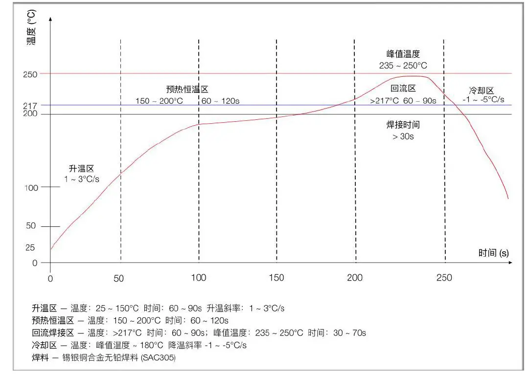
Figure 8 Reflow soldering curve
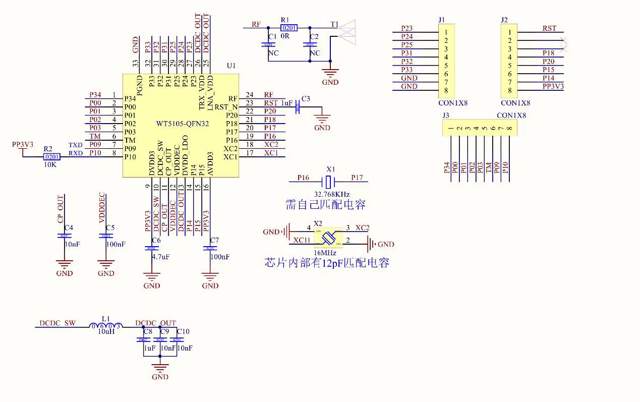
Schmatic Diagram
Serial At Command Description
The module will automatically identify and distinguish serial port data. Packets with “AT+” at the beginning will be defaulted to AT commands and parsed, and the processing result will be returned. Therefore, data in transparent transmission mode cannot start with “AT+” characters; non-AT commands The data will be forwarded by the module to the connected Bluetooth terminal
TEST COMMAN
- Command format: AT+TEST\r\n
- Return value: OK\r\n
- Content: Send AT test command, and return OK to indicate successful AT command test
Software version query command
- Command format: AT+VERSION?\r\n
- Return value: x.x.x\r\n
- Contents: Returns the current software version number of the module
MAC address operation command
Enturn value: xx:xx:xx:xx:xx:xx\r\n
Content: Return the module’s current MAC address
Serial baud rate operation command
- Command format: AT+BAUD=115200\r\n
- Return value: OK\r\n
- ERR:CODE\r\n
- Content: Re-modify the serial port baud rate of the module communication is 115200bps, return OK to indicate that the modification has been successful, and return ERR
- It means that the new serial port baud rate has failed to be modified, and the serial port baud rate defaults to 115200bps
Device name operation commands
- Command format: AT+NAME=WT5105-M1\r\n
- Return value: OK\r\n
- ERR:CODE\r\n
- Content: Rename the module name to WT5105-M1, the length of the name does not exceed 20 bytes
- Command format: AT+NAME?\r\n
- Return value: WT5105-M1\r\n
- Content: Query the current device name of the module, the serial port returns the current device name WT5105-M1
Bluetooth broadcast time interval setting command
- Command format: AT+ADV_INT=100\r\n
- Return value: OK\r\n
- ERR:CODE\r\n
- Content: Set the broadcast interval of Bluetooth to 100ms, the effective interval is set to 20ms-4000ms, return 0K means the setting is successful, ERR means the setting fails
Bluetooth connection interval setting
- Command format: AT+CIT=30,45\r\n
- Return value: OK\r\n
- ERR:CODE\r\n
- Content: Set the minimum Bluetooth connection interval to 30ms, the maximum connection interval to 45ms, and the effective Bluetooth connection interval to 10ms-4000ms
Bluetooth broadcast operation commands
- Command format: AT+ADV_STOP\r\n Return value: OK\r\n
- ERR:CODE\r\n
- Content: Stop Bluetooth broadcast Command format: AT+ADV_START\r\n Return value: OK\r\n
- ERR:CODE\r\n
- Content: Turn on Bluetooth radio
Restore factory configuration command
- Command format: AT+DEFAULT\r\n
- Return value: OK\r\n
- ERR:CODE\r\n
- Contents: Restore the module to the original factory mode, returning 0K means that the module starts to restore the factory mode; Bluetooth connection status, this command is not allowed
Custom product serial number
- Command format: AT+SN=1234\r\n
- Return value: OK\r\n
- ERR:CODE\r\n
- Content: The serial number of the custom product is in the broadcast data. If it returns OK, it means that the custom addition was successful, and if it returns ERR, it means that the addition failed. The possible reason is that the custom data exceeds the serial number requirement. The module serial number supports 0000-FFFF, and the default is FFFF. ; Bluetooth connection status, this command is not allowed
Custom broadcast data
- Command format: AT+MANU_DATA=1234\r\n
- Return value: OK\r\n
- ERR:CODE\r\n
- Content: The user can add custom broadcast data to the Bluetooth broadcast data. The maximum data length that can be added is 6 bytes; this command is not allowed in the Bluetooth connection status
Transmit power setting command
- Command format: AT+RFPM=3\r\n
- Return value: OK\r\n
- ERR:CODE\r\n
- Content: Reset the transmission power of Bluetooth; this command is not allowed in Bluetooth connection status
- Command format: AT+RFPM?\r\n
- Return value: 3dBm\r\n
- Content: Query the current Bluetooth transmit power
| Power level | Power value |
| 0 | 5dBm |
| 1 | 4dBm |
| 2 | 3dBm |
| 3 | 0dBm |
| 4 | -3dBm |
| 5 | -5dBm |
| 6 | -6dBm |
| 7 | -10dBm |
| 8 | -15dBm |
| 9 | -20dBm |
Sleep mode settings
- Command format: AT+SLEEP\r\n
- Return value: OK\r\n
- ERR:CODE\r\n
- Content: In order to reduce the power consumption of the module, the module can be put into deep sleep mode through this command, and the Bluetooth and serial port functions are closed; the standby current in this state is about 3uA; the module can be woken up by the external wake-up pin (P14)
Error Code Code Description
| ERROR CODE | Description | wrong reason |
| 1 | Invalid input | |
| 2 | Unsupported commands | |
| 3 | The current state does not allow parsing commands | |
| 4 | This command is not allowed in the current state | |
| 5 | The command has no action | |
| 6 | Invalid command parameter | |
| 7 | Hardware error | |
| 8 | Command processing timeout | |
| 9 | Other errors |
Ble Protocol Description
[SERVICE UUID:0x0201]
| Eigenvalues | Attributes | |
| 0x0202 | NOTIFY | |
| 0x0203 | WRITE,WRITE NO RESPONSE |
Integration instructions for host product manufacturers according to KDB 996369 D03 OEM
Manual v01
List of applicable FCC rules
FCC Part 15 Subpart C 15.247 & 15.209
Specific operational use conditions
The module is a Bluetooth module with BLE function.
- Operation Frequency: 2402-2480MHz
- Number of Channel: 40
- Modulation: GFSK
- Type: PCB Antenna
- Gain: 1 dBi Max.
The module can be used for mobile or portable applications with a maximum 1dBi antenna. The host manufacturer installing this module into their product must ensure that the final composite product complies with the FCC requirements by a technical assessment or evaluation to the FCC rules, including the transmitter operation. The host manufacturer has to be aware not to provide information to the end user regarding how to install or remove this RF module in the user’s manual of the end product which integrates this module. The end user manual shall include all required regulatory information/warning as show in this manual.
Limited module procedures
Not applicable. The module is a Single module and complies with the requirement of FCC Part 15.212.
Trace antenna designs
Not applicable. The module has its own antenna, and doesn’t need a host’s printed board microstrip trace antenna etc.
RF exposure considerations
The module must be installed in the host equipment such that at least 20cm is maintained between the antenna and users’ body; and if RF exposure statement or module layout is changed, then the host product manufacturer required to take responsibility of the module through a change in FCC ID or new application. The FCC ID of the module cannot be used on the final product. In these circumstances, the host manufacturer will be responsible for re-evaluating the end product (including the transmitter) and obtaining a separate FCC authorization.
Antennas
Antenna Specification are as follows:
- Type: PCB Antenna
- Gain: 1 dBi
- This device is intended only for host manufacturers under the following conditions:
The transmitter module may not be co-located with any other transmitter or antenna; The module shall be only used with the internal antenna(s) that has been originally tested and certified with this module. The antenna must be either permanently attached or employ ‘unique’ antenna coupler. As long as the conditions above are met, further transmitter test will not be required. However, the host manufacturer is still responsible for testing their end-product for any additional compliance requirements required with this module installed (for example, digital device emissions, PC peripheral requirements, etc.). - Label and compliance information
Host product manufacturers need to provide a physical or e-label stating “Contains FCC ID: 2AFOS-WT5105-M1” with their finished product. - Information on test modes and additional testing requirements
- Operation Frequency: 2402-2480MHz
- Number of Channel: 40
- Modulation: GFSK
Host manufacturer must preform test of radiated & conducted emission and spurious emission, etc according to the actual test modes for a stand-alone modular transmitter in a host, as well as for multiple simultaneously transmitting modules or other transmitters in a host product.
Only when all the test results of test modes comply with FCC requirements, then the end product can be sold legally.
- Additional testing, Part 15 Subpart B disclaimer
The modular transmitter is only FCC authorized for FCC Part 15 Subpart C 15.247 & 15.209 and that the host product manufacturer is responsible for compliance to any other FCC rules that apply to the host not covered by the modular transmitter grant of certification. If the grantee markets their product as being Part 15 Subpart B compliant (when it also contains unintentional-radiator digital circuity), then the grantee shall provide a notice stating that the final host product still requires Part 15 Subpart B compliance testing with the modular transmitter installed.
Federal Communication Commission Statement (FCC, U.S.)
This equipment has been tested and found to comply with the limits for a Class B digital device, pursuant to Part 15 of the FCC Rules. These limits are designed to provide reasonable protection against harmful interference in a residential installation. This equipment generates, uses and can radiate radio frequency energy and, if not installed and used in accordance with the instructions, may cause harmful interference to radio communications. However, there is no guarantee that interference will not occur in a particular installation. If this equipment does cause harmful interference to radio or television reception, which can be determined by turning the equipment off and on, the user is encouraged to try to correct the interference by one of the following measures:
- Reorient or relocate the receiving antenna.
- Increase the separation between the equipment and receiver.
- Connect the equipment into an outlet on a circuit different from that to which the receiver is connected.
- Consult the dealer or an experienced radio/TV technician for help.
This device complies with Part 15 of the FCC Rules. Operation is subject to the following two conditions:
- This device may not cause harmful interference, and
- This device must accept any interference received, including interference that may cause undesired operation.
FCC Caution:
Any changes or modifications not expressly approved by the party responsible for compliance could void the user’s authority to operate this equipment.
IMPORTANT NOTES
Co-location warning:
This transmitter must not be co-located or operating in conjunction with any other antenna or transmitter.
OEM integration instructions:
This device is intended only for OEM integrators under the following conditions:
The transmitter module may not be co-located with any other transmitter or antenna. The module shall be only used with the external antenna(s) that has been originally tested and certified with this module. As long as the conditions above are met, further transmitter test will not be required. However, the OEM integrator is still responsible for testing their end-product for any additional compliance requirements required with this module installed (for example, digital device emissions, PC peripheral requirements, etc.).
Validity of using the module certification:
In the event that these conditions cannot be met (for example certain laptop configurations or co-location with another transmitter), then the FCC authorization for this module in combination with the host equipment is no longer considered valid and the FCC ID of the module cannot be used on the final product. In these circumstances, the OEM integrator will be responsible for re-evaluating the end product (including the transmitter) and obtaining a separate FCC authorization.
End product labeling
The final end product must be labeled in a visible area with the following: “Contains Transmitter Module FCC ID: 2AFOS-WT5105-M1”.
Information that must be placed in the end user manual:
The OEM integrator has to be aware not to provide information to the end user regarding how to install or remove this RF module in the user’s manual of the end product which integrates this module. The end user manual shall include all required regulatory information/warning as show in this manual.


