Hi-Link HLK-B20 BLE 4.2 Wireless Module
Product description
HLK-B20 is a new low-consumption Bluetooth BLE 4.2 control module made by Hi-Link. This product is a Bluetooth-compliant module based on the universal serial interface. It has a built-in BLE 4.2 protocol stack, which can realize data conversion between the user serial port and Bluetooth interface.
Basic parameters
- High-speed ARM9E core MCU
- 2.4G/1T1R, BLE 4.2
- 160k programming space, 20KB RAM
- Power supply voltage 0.9-3.6v
- Ultra-low supply voltage, low power consumption
- Built-in crystal, high stability
- Small chip package 4×4
- Rich peripheral interface, SPI, I2C, ADC, UART, PWM, GPIO
- Widely used in the Internet of Things
- High-speed 10-bit multi-channel ADC with internal filtering
- Easy to connect, fast speed
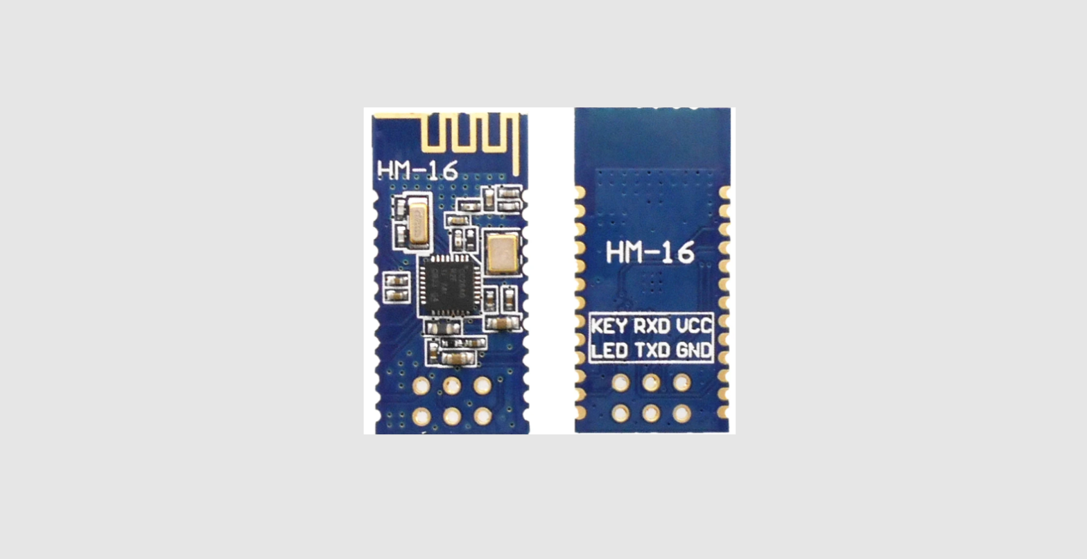
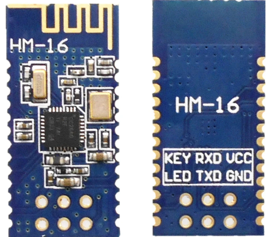
Product Overview
Technical specifications
| Transfer Protocol | Bluetooth standard: BLE 4.2 |
| Supply voltage | 0.9-3.6V |
| Air speed | 1Mbps |
| Number of channels | 40 |
| Frequency Range | 2400-2480MHZ |
| Transmit power | 4DB |
| Receiving sensitivity | -96dbm |
| Received power | 5.1ma |
| Transmit power | 4.5ma |
| Antenna type | External /internal antenna |
| Other parameters | |
| Status indicator | Status indication |
|
Environmental standard | Operating temperature: -40-125℃ |
| Working humidity: 10%-90%RH (Non-condensing) | |
| Storage temp.: -40-90℃ | |
| Storage humidity: 5%-90%RH (Non-condensing) | |
| Other performance | Band bandwidth optional: 1MHz |
Hardware description
HLK-B20 dimension as below:(L*W)=16mm*25mm 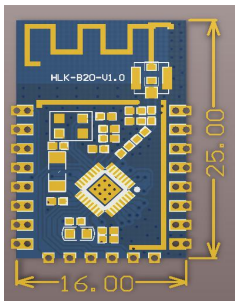
Block diagram 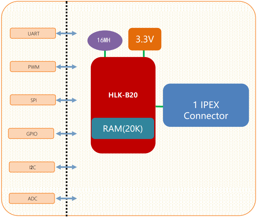
Default pin function
| No. | Network name | Type | Function description | Default features |
| 1 | RSTN | I | Chip enable, high efficiency | CPU reset |
| 2 | P07 | I/O | P07,SPI_NSS,PWM5 | GPIO,SPI,PWM |
| 3 | P14 | I/O | P14,PWM4 | GPIO,PWM |
| 4 | P10 | I/O | P10,PWM0 | GPIO,PWM |
| 5 | P11 | I/O | P11,PWM1 | GPIO,PWM |
| 6 | P12 | I/O | P12,PWM2 | GPIO,PWM |
| 7 | P13 | I/O | P13,PWM3 | GPIO,PWM |
| 8 | 3V3 | P | 3.3V power supply | Power |
| 9 | P31 | I/O | P31 | GPIO |
| 10 | P32 | I/O | P32 | GPIO |
| 11 | P17 | I/O | P17,uart2_rxd | GPIO,uart2 |
| 12 | P16 | I/O | P16, uart2_txd | GPIO,uart2 |
| 13 | P34 | I/O | P32 | GPIO |
| 14 | P33 | I/O | P33 | GPIO |
| 15 | GND | P | GND | GND |
| 16 | P02 | I/O | P02,SCL | GPIO,I2C |
| 17 | P03 | I/O | P03,SDA | GPIO,I2C |
| 18 | P04 | I/O | P04,SPI_CLK | GPIO,SPI |
| 19 | P05 | I/O | P05,SPI_MOSI | GPIO,SPI |
| 20 | P06 | I/O | P06,SPI_MISO | GPIO,SPI |
| 21 | P01 | I/O | Uart1_rxd | Uart1, Transparent transmission serial port |
| 22 | P00 | I/O | Uart1_txd | Uart1, Transparent transmission serial port |
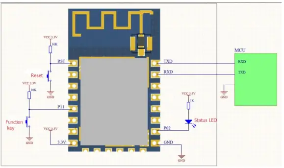
Test board description
The test board is mainly used to test the data transmission function of the HLK-B20’s Bluetooth and serial ports.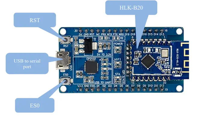 Restore factory settings
To ensure that all configuration procedures are correct, first reset the module to factory settings. Modules that are already in factory mode can skip this step. Provide 5V (1000mA) power supply to power on the module, wait for about 1 second, let the module start up. After the startup is completed, pull down the ES0 (PIN5) pin for more than 6S. When the LED corresponding to the STA is always on, it means that the module is restored the factory settings successfully, then release the ES0 pin, the system will automatically restart. The system is already in factory mode after rebooting.
Function description
The module function is mainly to realize the mutual conversion of Bluetooth data and serial data.
In this mode, the BLE Bluetooth device transmits the data to the HLK-B20 module via Bluetooth, and the HLK-B20 module sends the received data from the serial port. When the serial port gets data, theHLK-B20 sends the serial port data from the Bluetooth terminal to realize the conversion of serial data and Bluetooth data. When the HLK-B20 has a Bluetooth device connected, the HLK-B20 will turn off the broadcast of the Bluetooth name, and other Bluetooth devices will no longer be able to connect to the Lk-B20.
Serial port working state conversion
The module defines the working state of the serial port as two modes: transparent transmission mode and AT command mode.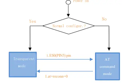
After normal power-on, the module directly enters the transparent mode. If Bluetooth is not connected, the data will not be sent out from Bluetooth. If Bluetooth is connected, the data will be sent out from Bluetooth. In any state, keeping the ES0 pin low for longer than Tes and less than Trst will immediately enter the AT command mode.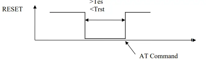
Led light indication meaning
- The status of the led connection module’s P02 pin, corresponding to the sta led on the test board:
- Double flash: Bluetooth is not connected, and is in transparent mode
- Triple flash: AT command mode
- Long extinction or fast flash: Bluetooth is connected, it will flash quickly when there is transparent data transmission
Parameter configuration method
The module configuration is mainly configured through the serial port AT command. Toconfigureparameters through the serial AT command, you need to let the module enter the AT command mode first.The serial port configuration tool HLK-B20_CONFIG, which configures the module throughtheATcommand mode, through the parameters of each configuration combination, provides a simple and convenient configuration process.
Serial port AT command configuration
AT instruction format
In AT mode, system parameters can be configured through the AT command of the serial port. The format of the instruction is as follows: at+[command]=[value]\r Different return values of the module will be returned depending on the different command. Example: “at+ble_name=blename\r” sets the module broadcast address to blame. Example: “at+ver=?\r” queries the module program version number.
| ver | Module Version |
| uart | Serial port configuration |
| default | Restore factory setting |
| ble_name | Bluetooth name |
| net_commit | Submit configuration parameters |
| reconn | Restart the serial port service |
| ble_status | Bluetooth connection status |
| Reboot | Restart the system |
Ver
| Function | Firmware version query |
| Format | at+ver=?\r |
| Parameter | No |
Uart
| Function | Serial port configuration settings |
| Format | at+uart=<baud>, <data>, <parity>, <stop>\r |
| Parameter | Baud: Baud rate Data: Data bit Parity: Check Digit Stop: Stop bit length |
net_commit
| Function | Submit network settings |
| Format | at+net_commit=< Net_commit >\r |
| Parameter | 0:invalid 1:Submit |
Reconn
| Function | Restart the serial port conversion service |
| Format | at+ reconn =< reconn >\r |
| Parameter | 0: invalid 1: Restart the serial port conversion service |
ble_status
| Function | Query Bluetooth connection status |
| Format | at+ ble_status =?\r |
| Parameter | 0: Not connected 1: Connected |
ble_name
| Function | Query Bluetooth connection status |
| Format | at+ ble_name =<blename>\r |
| Parameter | blename: Bluetooth name |
default
| Function | Restore factory setting |
| Format | at+ default =1\r |
| Parameter | No |
Reboot
| Function | Restart the system |
| Format | at+ reboot =1\r |
| Parameter | No |
Configuration Tool Description
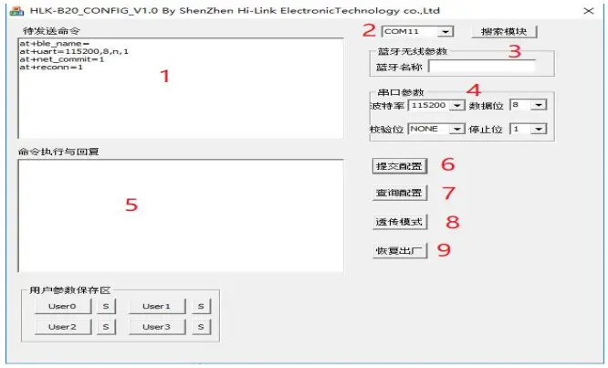
- Command window to be sent
- Serial port number selection
- Bluetooth name setting
- Serial port parameters
- Serial port return command
- Submit configuration
- Query configuration
- Enter transparent mode
- Restore factory settings
Transparent transmission minimum system
Bluetooth data transmission
Bluetooth data transmission is that after the Bluetooth connection is successful, the module will send the data received from the Bluetooth by the serial port, and the data received from the module serial port will be sent out by the Bluetooth. The module Bluetooth function only supports Bluetooth 4.2. Install the Bluetooth mobile phone test software HLK-BLE.apk, open the Bluetooth function of the mobile phone, and then open the app, it will search for the Bluetooth name at the beginning of HLK-BLE_on the app.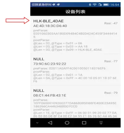
Then select the last item 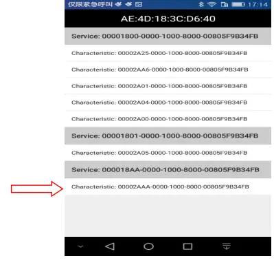
Then input the sent data in the send box, click Send, the data will be received on the serial port, and the data sent by the serial port will be received on the app.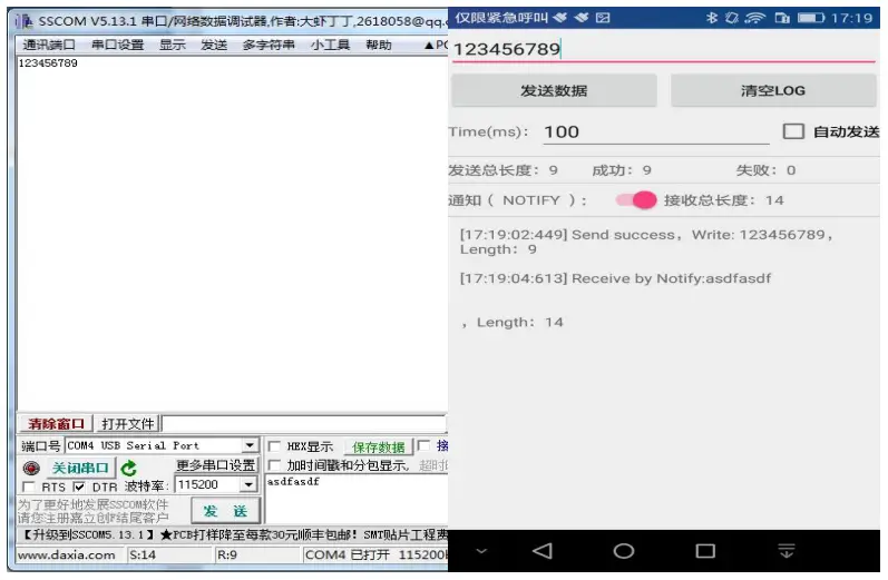
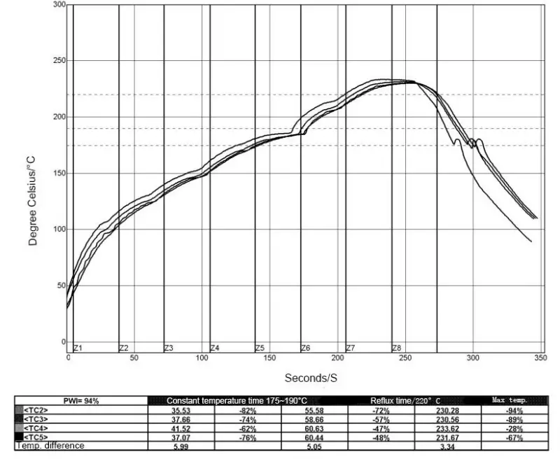
Reflow soldering temperature curve
When the module is over-fired, please strictly follow this temperature curve. If the temperature deviation of the reflow soldering is too large, the module will be damaged!
| Temperature setting (degrees Celsius) | |||||||||
| Warm zone | 1 | 2 | 3 | 4 | 5 | 6 | 7 | 8 | |
| Upper-temperature zone | 125 | 135 | 155 | 185 | 195 | 225 | 240 | 230 | |
| Lower temperature zone | 125 | 135 | 155 | 185 | 195 | 225 | 240 | 230 | |
| Conveyor speed: 70.0 cm/min | |||||||||
Appendix A Document Revision History
| Version number | Revision Scope | Date |
| 1.00 | 2019-4-15 |
- List of applicable FCC rules
FCC Part 15.247 - RF exposure considerations
This module is certified that complies with RF exposure requirements under 5mm RF distance. - Label and compliance information
FCC ID label on the final system must be labeled with “Contains FCC ID:
2AD56HLK-B20” or “Contains transmitter module FCC ID: 2AD56HLK-B20”. - Information on test modes and additional testing requirements
Contact Shenzhen HaiLingKe Electronic co.,Ltd will provide a stand-alone modular transmitter test mode. Additional testing and certification may be necessary when multiple modules are used in a host. - Additional testing, Part 15 Subpart B disclaimer
To ensure compliance with all non-transmitter functions the host manufacturer is responsible for ensuring compliance with the module(s) installed and fully operational. For example, if a host was previously authorized as an unintentional radiator under the Supplier’s Declaration of Conformity procedure without a transmitter-certified module and a module is added, the host manufacturer is responsible for ensuring that the after the module is installed and operational the host continues to be compliant with the Part 15B unintentional radiator requirements. Since this may depend on the details of how the module is integrated with the host, ShenZhen HaiLingKe Electronic co.,Ltd shall provide guidance to the host manufacturer for compliance with the Part 15B requirements.
FCC Warning
This device complies with Part 15 of the FCC Rules. Operation is subject to the following two conditions:
(1) This device may not cause harmful interference, and (2) this device must accept any interference received, including interference that may cause undesired operation. NOTE 1: This product has been tested and found to comply with the limits for a Class B digital device, pursuant to Part 15 of the FCC Rules. These limits are designed to provide reasonable protection against harmful interference in a residential installation. This product generates, uses, and can radiate radio frequency energy and, if not installed and used in accordance with the instructions, may cause harmful interference to radio communications. However, there is no guarantee that interference will not occur in a particular installation. If this product does cause harmful interference to radio or television reception, which can be determined by turning the equipment off and on, the user is encouraged to try to correct the interference by one or more of the following measures:
- Reorient or relocate the receiving antenna.
- Increase the separation between the equipment and receiver.
- Connect the equipment into an outlet on a circuit different from that to which the receiver is connected.
- Consult the dealer or an experienced radio/TV technician for help. NOTE 2: Any changes or modifications to this unit not expressly approved by the party responsible for compliance could void the user’s authority to operate the equipment.
FCC Radiation Exposure Statement:
This equipment complies with FCC radiation exposure limits set forth for an uncontrolled environment. End-users must follow the specific operating instructions for satisfying RF exposure compliance.
- Note 1: This module is certified that complies with RF exposure requirements under 5mm RF distance. This transmitter must not be co-located or operating in conjunction with any other antenna or transmitter.
- Note 2: Any modifications made to the module will void the Grant of Certification, this module is limited to OEM installation only and must not be sold to end-users, end-user has no manual instructions to remove or install the device, only software or operating procedure shall be placed in the end-user operating manual of final products.
- Note 3: The module may be operated only with the antenna with which it is authorized. Any antenna that is of the same type and of equal or less directional gain as an antenna that is authorized with the intentional radiator may be marketed with, and used with, that intentional radiator.


