LG Innotek ETWBCLUL05 Bluetooth Low Energy Module
PRODUCT NAME: Bluetooth Low Energy Module
MODEL NAME: ETWBCLUL05
The information contained herein is the exclusive property of LG Innotek and shall not be distributed, reproduced, or disclosed in whole or no in part without prior written permission of LG Innotek.
| Designed | Checked | Approved | LG Innotek Co., Ltd. | ||
| H.S. Kim | J.H. Chang | S.D. Choi | |||
| Document No. | |||||
| 2021.04.27 | 2021.04.27 | 2021.04.27 | Page | 9 | |
| Reg. Date: 2021.04.27 | User Manual | Rev. No: 1.0 |
| Rev. Date: 2021.04.27 | MODEL NAME: ETWBCLUL05 | Page : 1 / 9 |
| Reg. Date: 2021.04.27 | User Manual | Rev. No: 1.0 |
| Rev. Date: 2021.04.27 | MODEL NAME: ETWBCLUL05 | Page : 2 / 9 |
Features
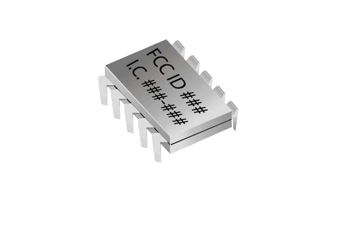
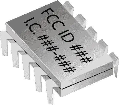
ETWBCLUL05 is the ultra-small size with antenna BT5.0 Low energy module.
ETWBCLUL05 is based on nRF52810 (Nordic) solution.
- Supported data rates: 1Mbps, 2Mbps Bluetooth® low energy mode
- -20 to +4dBm TX power, configurable in 4dB steps
- ARM® Cortex®-M4 32-bit processor, 64MHz
- Support LDO and DC/DC regulator system
- Integrated 2.4GHz Antenna (Option)
- 192kB flash and 24kB RAM
- 12-bit, 200ksps, ADC-8 configurable channels with programmable gain
- Support GPIO, PDM, PWM, SPI, I2C, UART, 64 level comparator
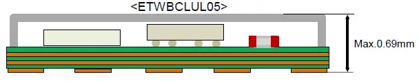
- Size : 3.28 x 5.26 x 0.69mm
- Application: Health care and medical, Wearable, Enterprise lighting, Remote controls, Computer peripherals, and I/O devices
| Reg. Date: 2021.04.27 | User Manual MODEL NAME: ETWBCLUL05 | Rev. No: 1.0 |
| Rev. Date: 2021.04.27 | Page : 3 / 9 |
Absolute maximum ratings
Caution: Stresses exceeding the absolute maximum ratings in Table 1 may damage the device. The device may not function or be operable above the recommended operating conditions and stressing the parts to these levels is not recommended.
In addition, extended exposure to stresses above the recommended operating conditions may affect device reliability. The absolute maximum ratings are stress ratings only.
TABLE
| Parameter | Min | Max | Unit |
| VBAT | – | +3.9 | V |
| Storage Humidity (40℃) | – | 90 | % |
| Storage Temperature | -20 | +85 | ℃ |
| MSL (Moisture Sensitivity Level) | 3 | Level | |
| ESD HBM | ±1 | – | kV |
Other conditions
- Do not use or store modules in the corrosive atmosphere, especially where chloride gas, sulfide gas, acid, alkali, salt, or the like are contained. Also, avoid exposure to moisture.
- Store the modules where the temperature and relative humidity do not exceed 5 to 40℃ and 20 to 60%.
- Assemble the modules within 6 months. Check the soldering ability in case of 6 months over.
- MSL Level 3 (Floor Life Time : 168Hrs. / Condition : ≤30℃, 60% RH), Standard : IPC / JEDEC J-STD-020C
| Reg. Date: 2021.04.27 | User Manual | Rev. No : 1.0 |
| Rev. Date: 2021.04.27 | MODEL NAME: ETWBCLUL05 | Page : 4 / 9 |
Recommendation operating conditions
| Parameter | Min | Typ | Max | Unit |
| Ambient Temperature | 0 | – | 60 | ℃ |
| Ambient Humidity (40℃) | – | – | 85 | % |
| Supply Voltage | 1.9 | 3.0 | 3.6 | Vdc |
Standard test conditions
The Test for electrical specification shall be performed under the following condition. Otherwise, the following conditions, not guaranteed this performance.
Ambient condition
| Temperature | 25 ± 5℃ |
| Humidity | 65 ± 5% |
Power supply voltages
| Input power | Supply Voltage |
| VBAT | 3.0V |
ESD Information
| ESD | Min. | Max. | Unit |
| Human Body Model (HBM) | ±1 | kV |
Note 1) Discharge : Contact, Interval : 1sec, Count : 1 time Condition : 100pF, 1500ohm, JEDC JESD22-A114
MSL
MSL Level 3 (Floor Life Time : 168Hrs. / Condition : ≤30℃, 60% RH) Standard : IPC / JEDEC J-STD-020C
| Reg. Date: 2021.04.27 | User Manual | Rev. No: 1.0 |
| Rev. Date: 2021.04.27 | MODEL NAME: ETWBCLUL05 | Page : 5 / 9 |
RF Specifications(Conducted Test)
| PARAMETER | TEST CONDITIONS | MIN | TYP | MAX | UNIT | |
| Receiver sensitivity | 1 Mbps | Packet length<=37 bytes, BER=0.1% | – | -94 | -80 | dBm |
| 2 Mbps | Packet length<=37 bytes, BER=0.1% | – | -91 | -80 | ||
| Maximum received signal strength | Maximum received signal strength at < 0.1% BER | -10 | 5 | – | dBm | |
| Maximum output power | Conducted Test | 0 | 4 | – | dBm | |
|
Modulation Characteristics | 1 Mbps | delta F1 average | 225 | – | 275 | kHz |
| ratio(delta F2/delta F1 ) | 80 | – | – | % | ||
| 2 Mbps | delta F1 average | 450 | – | 550 | kHz | |
| ratio(delta F2/delta F1 ) | 80 | – | – | % | ||
| Carrier frequency offset and drift | 1 Mbps | | f[n] | | – | – | 150 | kHz |
| | f0 –fn | | – | – | 50 | kHz | ||
| Carrier frequency offset and drift | 2 Mbps | | f[n] | | – | – | 150 | kHz |
| | f0 –fn | | – | – | 50 | kHz | ||
| Reg. Date: 2021.04.27 | User Manual | Rev. No: 1.0 |
| Rev. Date: 2021.04.27 | MODEL NAME: ETWBCLUL05 | Page : 6 / 9 |
Pin Description
| Pin No. | Pin Name | Pin Description |
| 1 | ANT Sub Line | Antenna Sub Pattern |
| 2 | NC | NC |
| 3 | NC | NC |
| 4 | NC | NC |
| 5 | ANT Feed | Internal Antenna Feeding |
| 6 | GND | Ground |
| 7 | RF Port | RF In / Out Port |
| 8 | GND | Ground |
| 9 | GPIO20 (P0.20) | General-purpose I/O pin |
| 10 | GPIO16 (P0.16) | General-purpose I/O pin |
| 11 | GPIO15 (P0.15) | General-purpose I/O pin |
| 12 | GPIO12 (P0.12) | General-purpose I/O pin |
| 13 | NC | NC |
| 14 | AIN1 (P0.03) | Analog input (General purpose I/O, COMP input, SAADC input) |
| 15 | GND | Ground |
| 16 | XL2 (P0.01) | General-purpose I/O pin, Connection for 32.768kHz crystal |
| 17 | XL1 (P0.00) | General-purpose I/O pin, Connection for 32.768kHz crystal |
| 18 | NC | NC |
| 19 | VBAT | Power supply pin |
| 20 | GND | Ground |
| 21 | DC DC-IN | DC-DC Inductor connection |
| 22 | GND | Ground |
| 23 | DC-DC Out | DC-DC Inductor connection |
| 24 | GND | Ground |
| 25 | GND | Ground |
| 26 | ANT Sub Line | Antenna Sub Pattern |
| 27 | Reset | Reset (General purpose I/O pin) |
| 28 | SWDIO | Serial wire debug I/O for debugging and programming |
| 29 | SWDCLK | Serial wire debug clock input for debugging and programming |
| 30 | AIN2 (P0.04) | Analog input (General purpose I/O, COMP input, SAADC input) |
| 31 | GPIO18 (P0.18) | General-purpose I/O pin |
| 32 | GPIO14 (P0.14) | General-purpose I/O pin |
| 33 | GND | Ground |
| 34 | GPIO8 (P0.08) | General-purpose I/O pin |
| 35 | GPIO11 (P0.11) | General-purpose I/O pin |
| Reg. Date: 2021.04.27 | User Manual | Rev. No: 1.0 |
| Rev. Date: 2021.04.27 | MODEL NAME: ETWBCLUL05 | Page : 8 / 9 |
Mechanical Dimension (Top View)
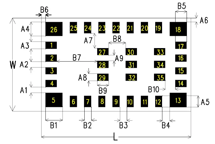
| DIM | mm | DIM | mm | DIM | mm |
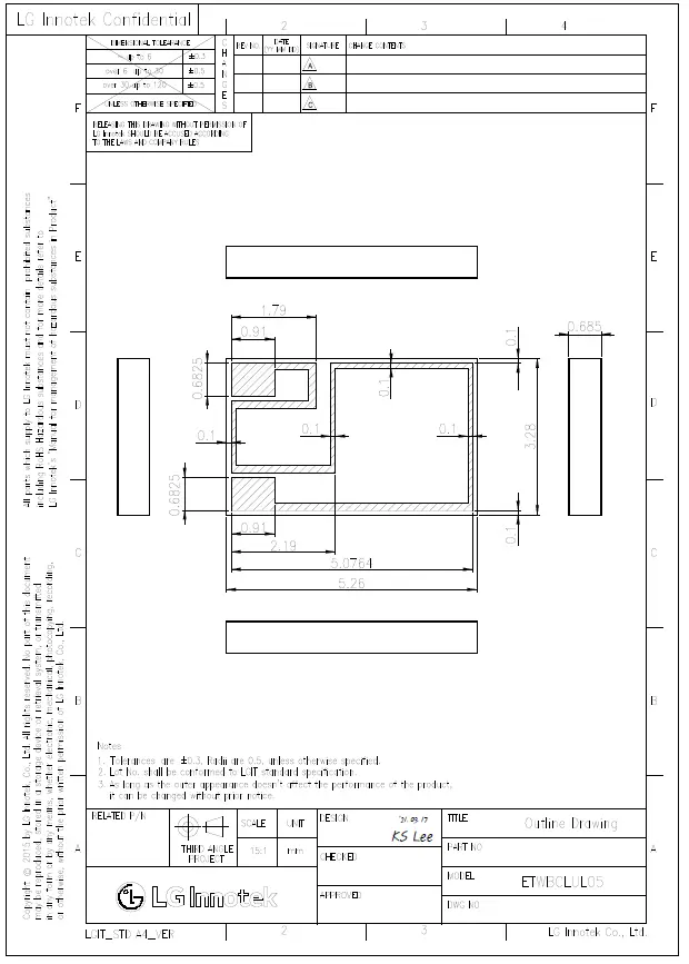
| W | 3.28.0 ± 0.2 | L | 5.26 ± 0.2 | B4 | 0.265 ± 0.05 |
| A1 | 0.2 ± 0.05 | A7 | 0.53 ± 0.05 | B5 | 0.4 ± 0.05 |
| A2 | 0.2 ± 0.05 | A8 | 0.25 ± 0.05 | B6 | 0.14 ± 0.05 |
| A3 | 0.25± 0.05 | A9 | 0.2 ± 0.05 | B7 | 1.43 ± 0.05 |
| A4 | 0.5 ± 0.05 | B1 | 0.6 ± 0.05 | B8 | 0.6 ± 0.05 |
| A5 | 0.4 ± 0.05 | B2 | 0.25 ± 0.05 | B9 | 0.4 ± 0.05 |
| A6 | 0.14 ± 0.05 | B3 | 0.25 ± 0.05 | B10 | 0.35 ± 0.05 |
| Reg. Date : 2021.04.27 | User Manual | Rev. No: 1.0 |
| Rev. Date: 2021.04.27 | MODEL NAME: ETWBCLUL05 | Page : 9 / 9 |
Outline Drawing
FCC MODULAR APPROVAL INFORMATION EXAMPLES for Manual
This device complies with Part 15 of the FCC Rules. Operation is subject to the following two conditions:
- This device may not cause harmful interference.
- This device must accept any interference received, including interference that may cause undesired operation.
CAUTION: Changes or modifications not expressly approved by the party responsible for compliance could void the user’s authority to operate the equipment.
NOTE: This equipment has been tested and found to comply with the limits for a Class B digital device, pursuant to Part 15 of the FCC Rules. These limits are designed to provide reasonable protection against harmful interference in a residential installation. This equipment generates uses and can radiate radio frequency energy and, if not installed and used in accordance with the instructions, may cause harmful interference to radio communications. However, there is no guarantee that interference will not occur in a particular installation. If this equipment does cause harmful interference to radio or television reception, which can be determined by turning the equipment off and on, the user is encouraged to try to correct the interference by one or more of the following measures:
- Reorient or relocate the receiving antenna.
- Increase the separation between the equipment and receiver.
- Connect the equipment into an outlet on a circuit different from that to which the receiver is connected.
- Consult the dealer or an experienced radio/TV technician for help.
FCC Radiation Exposure Statement:
This equipment complies with FCC radiation exposure limits set forth for an uncontrolled environment.
This equipment should be installed and operated with a minimum distance of 20cm between the radiator & your body.
OEM INTEGRATION INSTRUCTIONS
This device is intended only for OEM integrators under the following conditions:
The module must be installed in the host equipment such that 20 cm is maintained between the antenna
and users and the transmitter module may not be co-located with any other transmitter or antenna.
The module shall be only used with the internal onboard antenna that has been originally tested and certified with this module. External antennas are not supported. As long as these 3 conditions above are met,
further transmitter test will not be required.
However, the OEM integrator is still responsible for testing their end-product for any additional compliance requirements required with this module installed (for example, digital device emissions, PC peripheral requirements, etc.). The end-product may need Verification testing, Declaration of Conformity testing, a Permissive Class II Change or new Certification. Please involve an FCC certification specialist in order to determine what will be exactly applicable for the end product.
Validity of using the module certification:
In the event that these conditions cannot be met (for example certain laptop configurations or co-location with another transmitter), then the FCC authorization for this module in combination with the host equipment is no longer considered valid and the FCC ID of the module cannot be used on the final product. In these circumstances, the OEM integrator will be responsible for re-evaluating the end product (including the transmitter) and obtaining a separate FCC authorization. In such cases, please involve an FCC certification specialist in order to determine if a Permissive Class II Change or new Certification is required.
Upgrade Firmware:
The software provided for firmware upgrade will not be capable to affect any RF parameters as certified for the FCC for this module, in order to prevent compliance issues.
End product labeling:
This transmitter module is authorized only for use in devices where the antenna may be installed such that 20 cm may be maintained between the antenna and users. The final end product must be labeled in a visible area with the following: “Contains FCC ID: YZP-ETWBCLUL05”.
Information that must be placed in the end-user manual:
The OEM integrator has to be aware not to provide information to the end-user regarding how to install or remove this RF module in the user’s manual of the end product which integrates this module. The end-user manual shall include all required regulatory information/warning as shown in this manual.
WARNING
Changes or modifications not expressly approved by the manufacturer could void the user’s authority to operate the equipment.
CAUTION: Exposure to Radio Frequency Radiation.
Antenna shall be mounted in such a manner to minimize the potential for human contact during normal operation. The antenna should not be contacted during operation to avoid the possibility of exceeding the FCC radio frequency exposure limit.
IC Information
This device complies with Industry Canada license-exempt RSS standard(s). Operation is subject to the following two conditions:
- this device may not cause interference, and
- this device must accept any interference, including interference that may cause undesired operation of the device.
Information for OEM Integrator
This device is intended only for OEM integrators under the following conditions:
- The antenna must be installed such that 20 cm is maintained between the antenna and users, and
- The transmitter module may not be co-located with any other transmitter or antenna.
End product labeling
The label for the end product must include
“Contains FCC ID: YZP-ETWBCLUL05, Contains IC: 7414C-ETWBCLUL05”.
“ CAUTION: Exposure to Radio Frequency Radiation.
This equipment complies with FCC radiation exposure limits set forth for an uncontrolled environment. This equipment should be installed and operated with a minimum distance of 20cm between the radiator and your body. This transmitter module is authorized only for use in devices where the antenna may be installed such that 20 cm may be maintained between the antenna and users.”
Requirement per KDB996369 D03
List of applicable FCC rules
List the FCC rules that are applicable to the modular transmitter. These are the rules that specifically establish the bands of operation, the power, spurious emissions, and operating fundamental frequencies. DO NOT list compliance to unintentional-radiator rules (Part 15 Subpart B) since that is not a condition of a module grant that is extended to a host manufacturer. See also Section 2.10 below concerning the need to notify host manufacturers that further testing is required.3
Explanation: This module meets the requirements of FCC part 15C(15.247).
Summarize the specific operational use conditions
Describe use conditions that are applicable to the modular transmitter, including for example any limits on antennas, etc. For example, if point-to-point antennas are used that require reduction in power or compensation for cable loss, then this information must be in the instructions. If the use condition limitations extend to professional users, then instructions must state that this information also extends to the host manufacturer’s instruction manual. In addition, certain information may also be needed, such as peak gain per frequency band and minimum gain, specifically for master devices in
5 GHz DFS bands.
Explanation: The EUT has a PCB Antenna, and the antenna uses a permanently attached antenna that is not replaceable.
Limited module procedures
If a modular transmitter is approved as a “limited module,” then the module manufacturer is responsible for approving the host environment that the limited module is used with. The manufacturer of a limited module must describe, both in the filing and in the installation instructions, the alternative means that the limited module manufacturer uses to verify that the host meets the necessary requirements to satisfy the module limiting conditions.
A limited module manufacturer has the flexibility to define its alternative method to address the conditions that limit the initial approval, such as: shielding, minimum signaling amplitude, buffered modulation/data inputs, or power supply regulation. The alternative method could include that the limited module manufacturer reviews detailed test data or host designs prior to giving the host manufacturer approval. This limited module procedure is also applicable for RF exposure evaluation when it is necessary to demonstrate compliance in a specific host. The module manufacturer must state how control of the product into which the modular transmitter will be installed will be maintained such that full compliance of the product is always ensured. For additional hosts other than the specific host originally granted with a limited module, a Class II permissive change is required on the module grant to register the additional host as a specific host also approved with the module.
Explanation: The module is not a limited module.
Trace antenna designs
For a modular transmitter with trace antenna designs, see the guidance in Question 11 of KDB Publication 996369 D02 FAQ – Modules for Micro-Strip Antennas and traces. The integration information shall include for the TCB review the integration instructions for the following aspects:
the layout of trace design, parts list (BOM), antenna, connectors, and isolation requirements.
a) Information that includes permitted variances (e.g., trace boundary limits, thickness, length, width, shape(s), dielectric constant, and impedance as applicable for each type of antenna);
b) Each design shall be considered a different type (e.g., antenna length in multiple(s) of frequency, the wavelength, and antenna shape (traces in phase) can affect antenna gain and must be considered);
c) The parameters shall be provided in a manner permitting host manufacturers to design the printed circuit (PC) board layout;
d) Appropriate parts by manufacturer and specifications;
e) Test procedures for design verification; and
f) Production test procedures for ensuring compliance.
The module grantee shall provide a notice that any deviation(s) from the defined parameters of the antenna trace, as described by the instructions, require that the host product manufacturer must notify the module grantee that they wish to change the antenna trace design. In this case, a Class II permissive change application is required to be filed by the grantee, or the host manufacturer can take responsibility through the change in FCC ID (new application) procedure followed by a Class II permissive change application. Explanation: Yes, The module with trace antenna designs, and This manual has been shown the layout of trace design, antenna, connectors, and isolation requirements.
RF exposure considerations
It is essential for module grantees to clearly and explicitly state the RF exposure conditions that permit a host product manufacturer to use the module. Two types of instructions are required for RF exposure information: (1) to the host product manufacturer, to define the application conditions (mobile, portable – xx cm from a person’s body); and (2) additional text needed for the host product manufacturer to provide to end users in their end-product manuals. If RF exposure statements and use conditions are not provided, then the host product manufacturer is required to take responsibility of the module through a change in FCC ID (new application).
Explanation: This module complies with FCC RF radiation exposure limits set forth for an uncontrolled environment, This equipment should be installed and operated with a minimum distance of 20 centimeters between the radiator and your body.” This module is designed to comply with the FCC statement, FCC ID is: YZP-ETWBCLUL05
Antennas
A list of antennas included in the application for certification must be provided in the instructions. For modular transmitters approved as limited modules, all applicable professional installer instructions must be included as part of the information to the host product manufacturer. The antenna list shall also identify the antenna types (monopole, PIFA, dipole, etc. (note that for example an “Omni-directional antenna” is not considered to be a specific “antenna type”)).
For situations where the host product manufacturer is responsible for an external connector, for example with an RF pin and antenna trace design, the integration instructions shall inform the installer that a unique antenna connector must be used on Part 15 authorized transmitters used in the host product. The module manufacturers shall provide a list of acceptable unique connectors.
Explanation: Explanation: The EUT supports an external PCB antenna according. Antenna Gain is 0.08 dBi.
Label and compliance information
Grantees are responsible for the continued compliance of their modules to the FCC rules. This includes advising host product manufacturers that they need to provide a physical or e-label stating “Contains FCC ID” with their finished product. See Guidelines for Labeling and User Information for RF Devices – KDB Publication 784748.
Explanation: The host system using this module, should have a label in a visible area indicating the following texts: “Contains FCC ID: YZP-ETWBCLUL05.
Information on test modes and additional testing requirements5
Additional guidance for testing host products is given in KDB Publication 996369 D04 Module Integration Guide. Test modes should take into consideration different operational conditions for a stand-alone modular transmitter in a host, as well as for multiple simultaneously transmitting modules or other transmitters in a host product.
The grantee should provide information on how to configure test modes for host product evaluation for different operational conditions for a stand-alone modular transmitter in a host, versus with multiple, simultaneously transmitting modules or other transmitters in a host.
Grantees can increase the utility of their modular transmitters by providing special means, modes, or instructions that simulate or characterize a connection by enabling a transmitter. This can greatly simplify a host manufacturer’s determination that a module as installed in a host complies with FCC requirements.
Explanation: Top band can increase the utility of our modular transmitters by providing instructions that simulates or characterizes a connection by enabling a transmitter.
Additional testing, Part 15 Subpart B disclaimer
The grantee should include a statement that the modular transmitter is only FCC authorized for the specific rule parts (i.e., FCC transmitter rules) listed on the grant, and that the host product manufacturer is responsible for compliance to any other FCC rules that apply to the host not covered by the modular transmitter grant of certification. If the grantee markets their product as being Part 15 Subpart B compliant (when it also contains unintentional-radiator digital circuity), then the grantee shall provide a notice stating that the final host product still requires Part 15 Subpart B compliance testing with the modular transmitter installed.
Explanation: The module is without unintentional-radiator digital circuity, so the module does not require an evaluation by FCC Part 15 Subpart B. The host should be evaluated by the FCC Subpart B.


