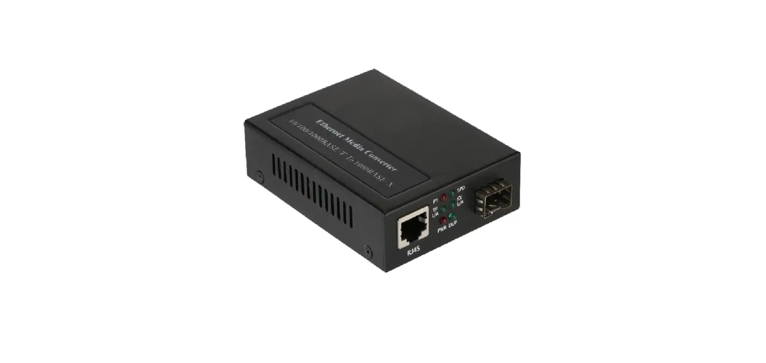
FIBERROAD FR-POE231 PoE PSE Ethernet Media Converter
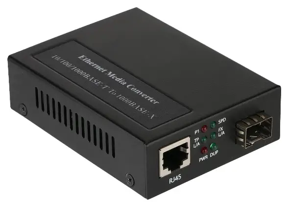
This user manual describes how to install and use the PoE PSE Ethernet Media Converter.
Instruction
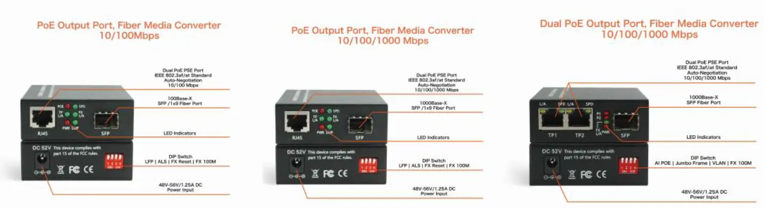
DIP Switch (FR POE231 And FR POE232)
| DIP Switch | Name | Status | Description |
| #1 | LFP | OFF | LFP Disable |
| ON | LFP Enable | ||
| #2 | ALS | OFF | ALS Disable |
| ON | ALS Enable | ||
| #3 | FX Reset | OFF | FX Reset Disable |
| ON | FX Reset Enable | ||
| #4 | FX100M | OFF | FX 1000M |
| ON | FX 100M |
DIP Switch (FR POE233)
| DIP Switch | Name | Status | Description |
| #1 | AI POE(Option) | OFF | AI POE Disable |
| ON | AI POE Enable | ||
| #2 | Jumbo Frame | OFF | ALS Disable |
| ON | ALS Enable | ||
| #3 | VLAN | OFF | VLAN Disable |
| ON | VLAN Enable | ||
| #4 | FX100M | OFF | FX 1000M |
| ON | FX 100M |
Notes:
- FX Reset When enabled, when the optical link is down, the media converter will reboot
- 3 ALS Automatic laser shutdown is a procedure to automatically shut down the laser when there is no input light and stop emitting optical signals 。
4. Ai PoE: When enabled, the PoE will restart if there is no data input to the UTP receiver.
5. FX Optical Fiber Port
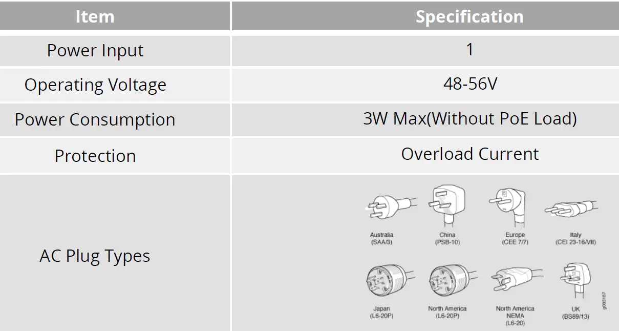
Power Supply Specification
Optical Fiber Port
SFP Transceiver Module
You can select different SFP modules as required (Please refer to our SFP selection list for the appropriate module). To insert/remove the SFP, the procedures are as follow:
- On the side panel, insert the SFP module into the SFP port until it is securely locked.
- Connect the optical fiber (1/2 core) to the LC connector(s) of the SFP.
- To remove the SFP module, press down the lock of the LC connector of the optical fiber to pull out the fiber cable.
- Pull down the SFP lever and hold its position. Pull out the SFP module from the SFP port.
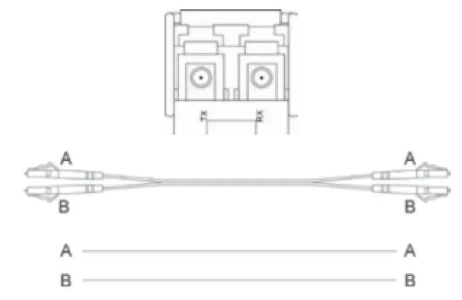 Notes: If you make your own cable, we suggest labeling the two sides of the same line with the same letter (A-to-A and B-to-B, shown as below, or A1-to-A2 and B1-to-B2).
The Port Status LEDs (FR-POE231 And FR-POE232)
| LED | State | Indication |
| PWR | On | Power On |
| Off | Power Off | |
| SPD | On | On: RJ45 is connected at the highest possible speed |
| Off | Off: RJ45 is not connected or is connected at a speed slower than the highest possible | |
| FX L/A | Solid | SFP is connected but no data is being receiver |
| Flashing | SFP is connected and data is being received | |
| PoE | On | PoE power is being supplied |
| Off | No PoE power is being supplied | |
| DUP | On | RJ45 is in full duplex mode |
| Off | RJ45 is in half duplex mode |
The Port Status LEDs (FR-POE233)
| LED | State | Indication |
| PWR | On | Power On |
| Off | Power Off | |
| SPD | On | On: RJ45 is connected at the highest possible speed |
| Off | Off: RJ45 is not connected or is connected at a speed slower than the highest possible | |
| FX L/A | Solid | SFP is connected but no data is being receiver |
| Flashing | SFP is connected and data is being received | |
| PoE(1 and 2) | On | PoE power is being supplied |
| Off | No PoE power is being supplied |
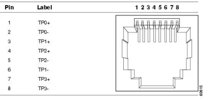
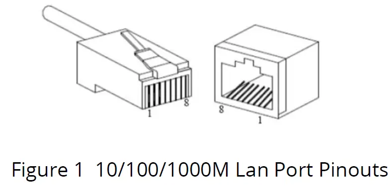
RJ45 Ethernet Port
RJ 45 port support automatic MDI/MDI-X operation. Can connect the PC, Server, Converter and HUB .Pin 1,2,3,6 Corresponding connections in MDI. 1→3, 2→6, 3→1, 6→2 are used as cross wiring in the MDI-X port of Converter and HUB.
10/100/1000Base-TX are used in MDI/MDI-X, the define of Pin in the table as below.
| 1000Mbps 1000Base-T, RJ45 Connector Pin Assignment | ||
| Pin | MDI Signal Definition | MDIX Signal Definition |
| 1 | BI_DA+ | BI_DB+ |
| + | BI_DA- | BI_DB- |
| 3 | BI_DB+ | BI_DA+ |
| 4 | BI_DC+ | BI_DD+ |
| 5 | BI_DC- | BI_DD- |
| 6 | BI_DB- | BI_DA- |
| 7 | BI_DD+ | BI_DC+ |
| 8 | BI_DD- | BI_DC- |
| 10/100Mbps 10/100Base-T, RJ45 Connector Pin Assignment | ||
| Pin | MDI Signal Definition | MDIX Signal Definition |
| 1 | TD+ | RD+ |
| 2 | TD- | RD- |
| 3 | RD+ | TD+ |
| 4 | NC | NC |
| 5 | NC | NC |
| 6 | RD- | TD- |
| 7 | NC | NC |
| 8 | NC | NC |
As aforementioned, an Ethernet crossover cable is adopted to connect two ports of the same configuration (i.e. MDI-to-MDI or MDIX-to-MDIX). However, it may generate some confusion and inconveniences when deploying two different kinds of Ethernet cables. The auto-MDI/MDIX technology is developed to fix this problem: It automatically switches between MDI and MDIX as required. Auto MDI/MDIX ports on newer device interfaces detect if the connection requires a crossover, then automatically choose the MDI or MDIX configuration to properly match the other end of the link. In this case, it doesn’t matter if you using straight through or crossover cables. The chart below shows cable types for MDI/MDIX and auto-MDIX.
| Setting | MDI/MDIX Device Type | |
| PC or other MDI Device | Switch, hub or other MDIX Device | |
| MDI | Crossover cable | Straight-through cable |
| MDIX | Straight-through cable | Crossover cable |
| Auto- MDI/MDIX | Either crossover or straight-through cable | |
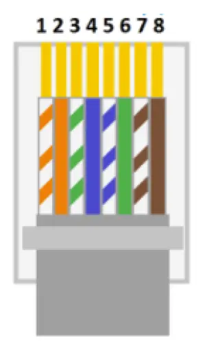
Power over Ethernet(PoE) Pinout Diagram
Power over Ethernet or PoE is a standard system that transmits or delivers electrical power along with data through the same cable. We know that there are different types of network cables are available such as cat6, cat7, cat5, etc, and different types of ports also available such as RJ45. RJ45 has a total of eight pins and it connects with an ethernet cable that consists of eight separate wires. All these eight wires are not used for the data transmission, so some of them can be used for electrical power transmission. As per the standard, the electrical current should interface with the data transmission and the cable should be safe.
The Power over Ethernet system works under the standardization of the (Institute of Electrical and Electronics Engineers)IEEE 802.3 committee. Generally, PoE delivers 47-57V DC power. This PoE system is used for both data and power transmission purposes in Internet Protocol(IP) cameras, Wireless Access points(WAPs), Voice over Internet Protocol(VoIP), etc.
According to the IEEE standard cat5 or better cable is required for the transmission of high power levels. But cat3 cable also can be used if less power transmission is required. The PoE system was physically implemented under the specification of IEEE 802.3af-2003. Also, we know that there are two categories for the RJ45 colour code – T568A and T568B.
IEEE 802.3af -2003 Standard PoE Pinout Diagram for T568A
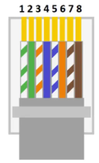
| No. | Description |
| 1 | White Green(TX+) |
| 2 | Green(TX-) |
| 3 | White Orange(RX+) |
| 4 | Blue(DC+) – PoE |
| 5 | White Blue(DC+) – PoE |
| 6 | Orange(RX-) |
| 7 | White Brown(DC-) – PoE |
| 8 | Brown(DC-) – PoE |
| No. | Description |
| 1 | White Orange(TX+) |
| 2 | Orange(TX-) |
| 3 | White Green(RX+) |
| 4 | Blue(DC+) – PoE |
| 5 | White Blue(DC+) – PoE |
| 6 | Green(RX-) |
| 7 | White Brown(DC-) – PoE |
| 8 | Brown(DC-) – PoE |
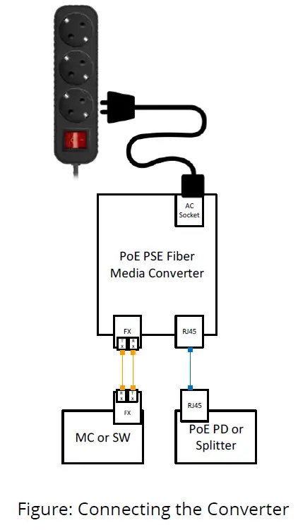
Installation
Before installation, confirm that the work environment meet the installation require, including the power needs and abundant space. Whether it is close to the connection equipment and other equipment are prepared or not.
- Avoid in the sunshine, keep away from the heat fountainhead or the area where in intense EMI.
- Examine the cables and plugs that installation requirements.
- Examine whether the cables be seemly or not (less than 100m) according to reasonable scheme.
- Power: AC220V power input
- Environment:
working temperature: 0~50℃ (32 to 122℉)
Storage Temperature: -20~70℃ (-4 to +158℉)
Relative humidity 5%~95% (noncondensing)
Assembly, Startup, and Dismantling
- Installation: Mount the Micro type unit onto a fixture, or camera housings, e.g. a plank, (either on the wall or on a flat surface) with at least 2 screws piercing through the holes on the mounting frame to secure it in position.
- Startup: Connect the supply voltage to start up the Media Converter via the terminal block.
- Dismantling: Locate and remove the securing screws. Usually, but not limited to, at least 2 screws.
Wiring Requirements
Cable laying need to meet the following requirements,
- It is needed to check whether the type, quantity and specification of cable match the requirement before cable laying;
- It is needed to check the cable is damaged or not, factory records and quality assurance booklet before cable laying;
- The required cable specification, quantity, direction and laying position need to match construction requirements, and cable length depends on actual position;
- All the cable cannot have break-down and terminal in the middle;
- Cables should be straight in the hallways and turning;
- Cable should be straight in the groove, and cannot beyond the groove in case of holding back the inlet and outlet holes. Cables should be banded and fixed when they are out of the groove;
- User cable should be separated from the power lines. Cables, power lines and grounding lines cannot be overlapped and mixed when they are in the same groove road. When cable is too long, it cannot hold down other cable, but structure in the middle of alignment rack;
- Pigtail cannot be tied and swerved as less as possible. Swerving radius cannot be too small (small swerving causes terrible loss of link). Its banding should be moderate, not too tight, and should be separated from other cables;
- It should have corresponding simple signal at both sides of the cable for maintaining.
| Connector | Description |
|
TP Port | 10/100BASE-TX Auto-Negotiation Auto-MDIX Flow control for Full-Duplex Backpressure for Half Duplex |
| 10/100/1000BASE-TX Auto-Negotiation Auto-MDIX ONLY for Auto- Negotiation Flow control for Full-Duplex ONLY | |
| Fiber Port | 1000Base-SX/LC(SC/LC) with Flow Control |
| Single Fiber TX1310nm/RX1550nm 10km |
Cable Connection Parameter
- 1000BASE-SX/LX networks only support full-duplex mode. The Switch based Media Converter breaks up TP and Fiber segments’ collision domain to extend the cabling distance.
- UTP Cables: CAT5, or above CAT5e class UTP cables
- UTP Cable Limitations: Max. Length up to 328 feet (100 m)
- Fiber Cables:
- 1000BASE-SX: 50/125, 62.5/125, or 100/140μm multimode
- 1000BASE-LX: 8.3/125, 8.7/125, 9/125 or 10/125μm single-mode
| Connector | Multimode Fiber | Sigle-mode Fiber | ||
| 1000Base- SX(850nm) | Bandwidth MHZ-KM | Distance | Bandwidth MHZ- KM | Distance |
| 260 | 220m | 400 | 500m | |
| 200 | 275m | 500 | 550m | |
| 1000Base-LX (1310nm/1550nm) | Single-mode Fiber 9/125um:2km Single-mode Transceiver 1310nm: 10/20km Single-mode Transceiver 1550nm: 40-120km | |||
Specifications
| LED | State | Indication |
| PWR | On | Power On |
| Off | Power Off | |
| SPD | On | On: RJ45 is connected at the highest possible speed |
| Off | Off: RJ45 is not connected or is connected at a speed slower than the highest possible | |
| FX L/A | Solid | SFP is connected but no data is being receiver |
| Flashing | SFP is connected and data is being received | |
| PoE | On | PoE power is being supplied |
| Off | No PoE power is being supplied | |
| DUP | On | RJ45 is in full duplex mode |
| Off | RJ45 is in half duplex mode |
| Ethernet Standards | |
|
Standards | IEEE802.3i 10Base-T IEEE802.3u 100Base-TX & 100Base-FX IEEE802.3ab 1000Base-T IEEE802.3z 1000Base-X IEEE802.3x Flow Control IEEE802.3af 15W PoE IEEE802.3at 30W PoE+ |
| Switching Capacity | 200Mbps(FR-POE231) 2 Gbps(FR-POE232) 6Gbps(FR-POE233) |
| Jumbo Frames | 9K |
| Power | |
| Power Input | 1 |
| Operating Voltage | 48-56VDC |
| PoE Power Capacity | IEEE802.3 af : 15.4W (x2 FR-POE233) IEEE802.3 at : 30W (x2 FR-POE233) |
| Power Consumption | af mode: 20W (x2 FR-POE233) at mode: 35W (x2 FR-POE233) |
| Protection | Over Currency |
| Mechanical | |
| Housing | Metal |
| Dimensions | 94mm×71mm×26mm(W x D x H) 3.70 x 2.80 x 1.02in |
| IP Rating | IP30 |
| Weight | 0.2kg/0.44lb(Bare Hardware) |
| Installation | Desktop or Wall Mount |
| Environmental | |
| Temperature | Operating: 0 to 50℃ (32 to 122℉) Storage: -20 to +70℃ (-4 to +158℉) |
| Humidity | 5 to 95% noncondensing |
| Altitude | <3000m(<10000 ft.) |
| MTBF | 100,819 Hours |
| MTBF Standard | Telcordia SR-332 GB 25℃ |
| Heat Dissipation | 113 BTU/h (With 30W PoE) |
| Cooling | Passive Cooling |
| Noise Level | 0 dBA |
Regulatory Information
Electronic Emission Notices
This equipment has been tested and found to comply with the FCC Part 15, Subpart B, Class A and protection requirements of European Emission Standard as follows: EMI Comply with FCC Part 15 Class A & CE Mark Approval LVD EN 62368-1 Safety UL and others by request
FCC Class a statement
This equipment generates, uses, and can radiate radio-frequency energy, and if not installed and used properly, that is, in strict accordance with the manufacturer’s instructions, may cause interference to radio communication. It has been tested and found to comply with the limits for a Class A computing device in accordance with the specifications in Subpart B of Part 15 of FCC rules, which are designed to provide reasonable protection against such interference when the equipment is operated in a commercial environment. Operation of this equipment in a residential area is likely to cause interference, in which case the user at his own expense will be required to take whatever measures may be necessary to correct the interference.
Changes or modifications not expressly approved by the party responsible for compliance could void the user’s authority to operate the equipment.
This digital apparatus does not exceed the Class A limits for radio noise emission from digital apparatus set out in the Radio Interference Regulation of Industry Canada.
Disclaimer
Fiberroad Technology Co., Ltd shall not be liable for damages of any kind, including, but not limited to, punitive, consequential or cost of cover damages, resulting from any errors in the product information or specifications set forth in this document and Fiberroad Technology Co., Ltd may revise this document at any time without notice.
Trademarks used in this manual
Fiberroad Technology and the Fiberroad logo type and mark are registered trademarks of Fiberroad Technology Co., Ltd . Any other trademarks mentioned in this manual are acknowledged to be the property of the trademark owners.

 Media Converter User Manual")


