![]() PD-9601GCS/AC
PD-9601GCS/AC
PoE Media Converter User Installation Guide
Introduction
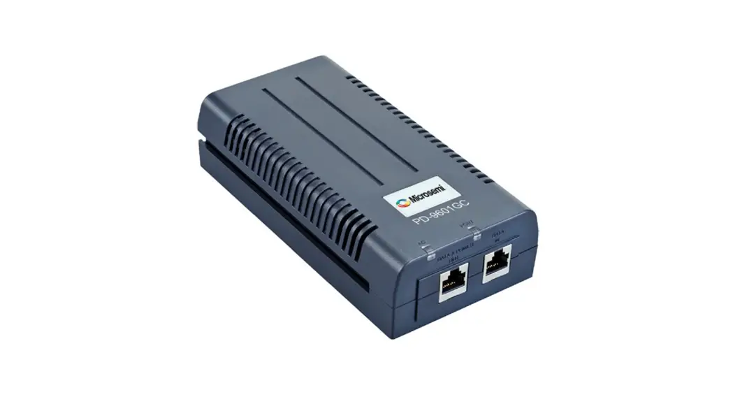
Microchip’s family of PD-9601GCS/AC is a Power over Ethernet (PoE) Media converter that injects power over data-carrying Ethernet cabling.
PD-9601GCS/AC complies with IEEE 802.3af standards, with guaranteed output power of 90W. These power levels allow usage by a new range of Ethernet-based applications such as PTZ IP cameras, Wi-Fi 802.3ac Access Points, Point-to-Point wireless radios, and more. The PD-9601GCS/AC Data and Power Output port is designed to carry gigabit Ethernet data and power over a standard CAT5e cable, delivered through 4-pair wires (Alt A: 3,6 (+) and 1,2 (-) ; Alt B: 4,5 (+) and 7,8 (-)). ® 802.3bt, IEEE ® 802.3at and IEEE ®
CAUTION: The PD-9601GCS/AC is designed for indoor applications only.
Features
PD-9601GCS/AC PoE Media converter offers the following important features:
- 1-port PoE output
- Guaranteed power of 90W
- Compact product size
- Universal AC input: 100 VAC to 240 VAC
- Standard compliance: IEEE 802.3 af/at/bt
Standards and Safety Guidelines
The following sections mention the standard and safety guidelines for the product.
1.1 Part Number Definition
PD-9601GCS/AC: 4-pairs AC input family.
Table 1-1. Part Number Definition
| Symbol | Description |
| GCS | Represents the bandwidth (10/100/1000 Mbps). |
| AC | Media converter has AC input. |
1.2 Electromagnetic Compatibility Approvals
Microchip’s PD-9601GCS/AC Media converter complies with the following standards:
- FCC Part 15: Class B
- EN55032: Class B
- Canadian ICES-003
- EN55024
- VCCI
1.3 Safety Standard Approvals
Microchip meets the following safety standards. Consult Microchip for the complete list of safety certifications.
- UL/cUL per UL62368-1
- GS Compliance per EN62368-1
1.4 GS Marking
GS marking on this product indicates that the product complies with the German Product Safety Act.
1.5 Safety Information
Read the safety information before using the PoE Media converter unit.
1.5.1 General Guidelines
Read the following safety information before carrying out any installation, removal, or maintenance procedure on the PoE Media converter unit. Warnings contain directions to be followed for the safety of personal and product.
1.5.2 Important Safety Information
Read the following important safety information before using the unit.
Setting up the AC power cord:
- The power cord must have regulatory agency approval for the specific country in which it is used (i.e., UL, CSA, VDE, and so on).
- The power cord must be a three-conductor type (two current carrying conductors; one ground conductor) terminated on one end by an IEC 60320 appliance coupler (for connection to the PoE Media converter), and on the other end by a plug containing a ground (earth) contact.
- The power cord must be rated for a minimum of 250Vac RMS operation, with a minimum rated current capacity of 5 amps (or a minimum wire gauge of 18 AWG (0.75mm).
Note: The Data-In PoE injector and PoE ports are shielded RJ45 data sockets. They cannot be used as Plain Old Telephone Service (POTS) telephone sockets. Only RJ45 data connectors may be connected to these sockets. 2 - The AC wall socket-outlet must be near the PoE Media converter and easily accessible. You can remove AC power from the PoE Media converter by disconnecting the AC power cord from either the wall socket-outlet or the PoE media converter appliance coupler.
- The PoE Media converter Data-In and Data and Power Out interfaces are qualified as SELV (Safety Extra-Low Voltage) circuits according to IEC 60950-1. These interfaces can only be connected to SELV interfaces on other equipment.
1.5.3 Warnings
- Read the installation instructions before connecting the PoE Media converter to its power source.
- Follow basic electricity safety measures whenever connecting the PoE Media converter to its power source.
- A voltage mismatch can cause equipment damage and may pose a fire hazard. If the voltage indicated on the label is different from the power outlet voltage, do not connect the PoE Media converter to this power outlet.
PoE Media Converter Hardware Installation
The following sections describe the procedure to install the PD-9601GCS/AC PoE Media converter unit.
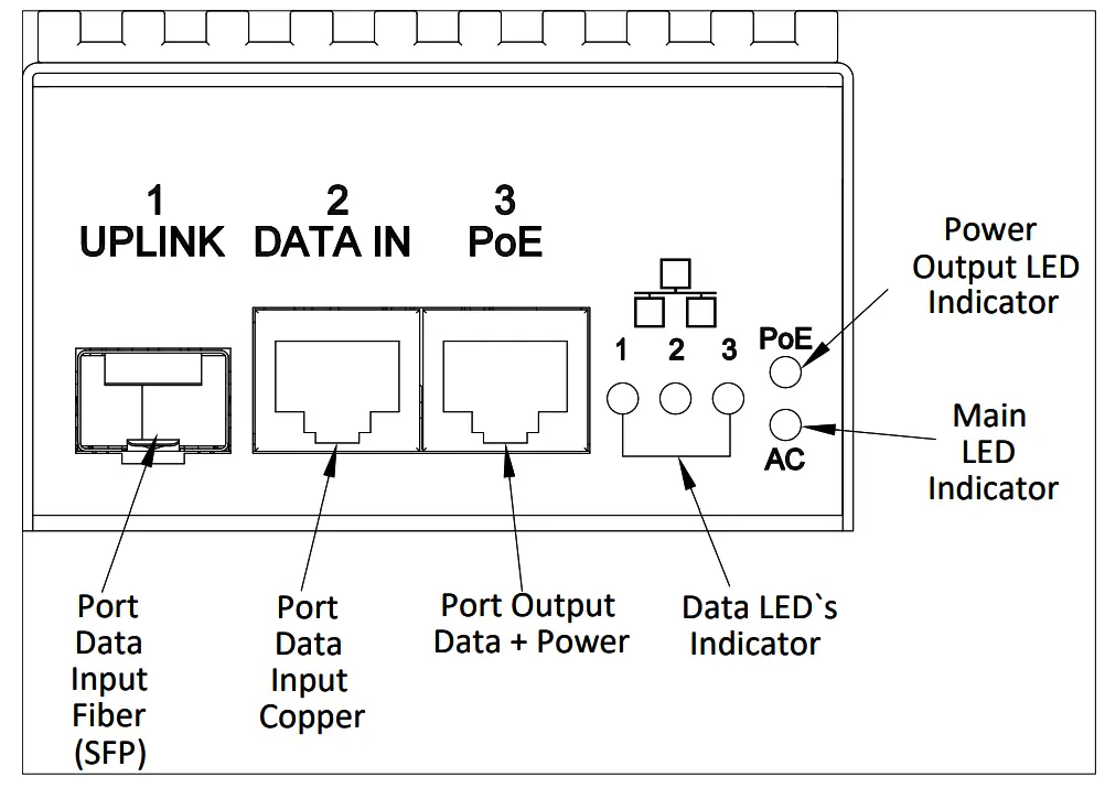
Figure 2-1. Installing the PD-9601GCS/AC
2.1 Media Converter Installation
Install the media converter according to following procedures.
- Ensure that AC power is applied to the PoE Media Convertor, using an AC cable with an appropriate ground connection.
- Connect the PoE Media Convertor to an AC outlet (100VAC–240VAC), using a standard power cord.
2.2 Installation of Optical to PoE Application
Install the optical fiber cable to the PoE Media converter according to following procedures.
- Insert the SFP transceiver into the SFP cage (uplink port). The PD-9601GCS/AC supports multi and single mode transceiver.
- Connect the optical fiber cable to the transceiver.
- Connect the other end of the cable to the network transceiver.
- Connect the PoE port to the Powered Device (PD) using a Cat5e (or higher) cable.
2.3 Installation of Copper to PoE Application
- Connect the DATA IN port to the network using a Cat5e (or higher) cable.
- Connect the PoE port to the PD using a Cat5e (or higher) cable.
2.4 Three Ports Converter Installation
Note: Read installation instructions before installing the PD-9601GCS/AC PoE Media converter.
The product supports simulated use of all 3 ports such as two data inputs and one PoE output which acts as a switch.
- Insert the SFP transceiver into the SFP cage (uplink port). The PD-9601GCS/AC support both multi and single mode transceiver.
- Connect the optical fiber cable to the transceiver.
- Connect the other end of the cable to the network transceiver.
- Connect the Copper DATA IN port to a non-PoE end-device using a Cat5e (or higher) cable.
- Connect the PoE port to the PD using a Cat5e (or higher) cable.
2.5 Indicators
The following table lists the set of indicators displaying the status of the PoE Media converter and its ports.
Table 2-1. Port Indicator LED
Port Indicator LEDs | Indication |
| Main LED | |
| OFF | Power OFF Indication |
| Green ON | Power ON Indication |
| Data LEDs | |
| OFF | No Link |
| Green ON | Link |
| Green Blink | Data Transfer |
| PoE LED | |
| OFF | No Output Power |
| Yellow ON | Power Over 2-pairs (3, 6 and 1, 2) |
| Green ON | Power Over all 4-pairs |
Troubleshooting
The following sections describe the troubleshooting procedures to address any problems with the unit.
3.1 Preliminary Steps
Before mounting the PD-9601GCS/AC PoE Media converter to a fixed location:
- Read installation instructions before connecting the PD-9601GCS/AC to its power source.
- There is no ON/OFF switch on the Media converter, simply plug the PD-9601GCS/AC into an AC power source.
- Verify that a PoE Ready Ethernet-compatible device is connected.
- Do not cover PD-9601GCS/AC or block airflow to the unit with any foreign objects. Keep PD-9601GCS/AC away from excessive heat and humidity, and free from vibration and dust.
- Ensure that cable length from Ethernet network source to the terminal does not exceed 100 meters (330 feet).
This Media converter is not a repeater and does not amplify Ethernet data signal. - Use a splitter, if necessary, and ensure that the splitter is connected near the terminal and not on the PD-9601GCS/AC.
3.2 Troubleshooting Steps
The following table lists problem and resolution sequences to assist in troubleshooting minor operating problems. If the following steps do not solve your problem, contact the dealer for further assistance.
Table 3-1. Troubleshooting Steps
| Problem | Corrective Steps |
| Media converter does not power-up. | 1.Verify that an approved power cord is used. 2.Ensure that the power cord is properly connected. 3.Verify that the voltage at the power inlet is between 100 VAC to 240 VAC. 4.Remove and re-apply power to the device and check indicators during power- up sequence. |
| A port indicator is not lit and corresponding PD does not operate. | 1.The media converter did not detect a PD and therefore the port is not enabled. 2.Verify that the PD is designed for PoE operation according to IEEE 802.3 af/at/bt standard. 3.Verify that you are using a standard straight‑wired four-pair cable (Category 5e) 4.Ensure that the input Ethernet cable is connected to the DATA IN port. 5.Verify that the PD is connected to the Data and Power port (PoE). 6.Try reconnecting the same PD again with another media converter. If it works, there is likely a bad port or RJ45 connection. 7.Verify that there is no short over any of the twisted pair cables or over the RJ45 connectors. 8.If an external power splitter is in use, replace it with a viable splitter. |
| End device operates but there is no data link.
| 1.Verify that the port indicator on the front panel is continuously lit. 2.Verify that for this link you are using a standard UTP/FTP Category 5e straight (non-crossover) cabling, with all four pairs, and that the link is 100 meters long 3.Verify that the Ethernet cable length is less than 100 meters PoE Media converter to the load/remote terminal. 4.Try reconnecting the same PD into a different media converter. If it works, there is probably a faulty port or RJ45 connection. 5.If an external power splitter is in use, replace it with a viable splitter. |
| SFP transceiver no data connection.
| 1.Verify that the transceivers are inserted in the transceivers cage. 2.Verify that the similar type of transceivers are applied on both fiber optic cable ends (Multi or Single mode). 3.Verify that the fiber optic cable is compatible with the transceivers type. 4.Verify that the fiber optic cable doesn’t exceed the transceivers type maximum length. 5.Try reconnecting the fiber optic cable to the transceivers. |
Specifications
The following sections provide detailed unit specifications of PD-9601GCS/AC.
4.1 Physical Specifications
Table 4-1. Dimensions
| Parameter | Dimensions | |
| In mm | In inch | |
| Height | 50 | 3.15 |
| Width | 80 | 1.97 |
| Length | 160 | 6.29 |
Table 4-2. Physical Specifications
| Part Number | Weight |
| PD-9601GCS/AC | 950 g (2.1 lb) |
4.2 Environmental Specifications
Table 4-3. Environmental Specifications
| Mode | Temperature | Humidity | |
| Output Power at 90W | Output Power at 60W | ||
| Operating | -10 °C to 45 °C 14 °F to 113 °F | -10 °C to 55 °C 14 °F to 131 °F | 90% (non-condensing allowed) |
| Storage | –20 °C to 70 °C –4 °F to 158 °F | 95% (non-condensing allowed) | |
4.3 Electrical Specifications
Table 4-4. Electrical Specifications
| Parameter | Value |
| AC Input Voltage | 100 VAC to 240 VAC at 50Hz/60 Hz |
| Maximal Input Current | 1.6A Maximum |
| Available Output Power | 90W |
| Nominal Output Voltage | 54VDC |
4.4 Ethernet Interface
Table 4-5. Ethernet Interface
| Input (Data In): Ethernet 10/100/1000Base-T | RJ45 female socket. |
| Input (Data In): Ethernet 1000BASE-X Fiber | SFP Cage Supports Single-Mode and Multi-Mode transceivers. |
| Output (Data and Power Out): Ethernet 10/100/1000Base-T + 54VDC | RJ45 female socket, with DC voltage on wire 4-pairs: 1-2 and 3-6; 4-5 and 7-8. |
Contacting Technical Support
If you encounter any problems while installing or using this product, consult Microchip technical support team through the website or contact on the following number:
USA/Canada
Telephone: +1 877 480 2323
Internet: www.microchip.com/support
Revision History
| Revision | Date | Description |
| A | 03/2022 | Initial Revision. |
The Microchip Website
Microchip provides online support via our website at www.microchip.com/. This website is used to make files and information easily available to customers. Some of the content available includes:
- Product Support – Data sheets and errata, application notes and sample programs, design resources, user’s guides and hardware support documents, latest software releases and archived software
- General Technical Support – Frequently Asked Questions (FAQs), technical support requests, online discussion groups, Microchip design partner program member listing
- Business of Microchip – Product selector and ordering guides, latest Microchip press releases, listing of seminars and events, listings of Microchip sales offices, distributors and factory representatives
Product Change Notification Service
Microchip’s product change notification service helps keep customers current on Microchip products. Subscribers will receive email notification whenever there are changes, updates, revisions or errata related to a specified product family or development tool of interest.
To register, go to www.microchip.com/pcn and follow the registration instructions.
Customer Support
Users of Microchip products can receive assistance through several channels:
- Distributor or Representative
- Local Sales Office
- Embedded Solutions Engineer (ESE)
- Technical Support
Customers should contact their distributor, representative or ESE for support. Local sales offices are also available to help customers. A listing of sales offices and locations is included in this document.
Technical support is available through the website at: www.microchip.com/support
Microchip Devices Code Protection Feature
Note the following details of the code protection feature on Microchip products:
- Microchip products meet the specifications contained in their particular Microchip Data Sheet.
- Microchip believes that its family of products is secure when used in the intended manner, within operating specifications, and under normal conditions.
- Microchip values and aggressively protects its intellectual property rights. Attempts to breach the code protection features of Microchip product is strictly prohibited and may violate the Digital Millennium Copyright Act.
- Neither Microchip nor any other semiconductor manufacturer can guarantee the security of its code. Code protection does not mean that we are guaranteeing the product is “unbreakable”. Code protection is constantly evolving. Microchip is committed to continuously improving the code protection features of our products.
Legal Notice
This publication and the information herein may be used only with Microchip products, including to design, test, and integrate Microchip products with your application. Use of this information in any other manner violates these terms. Information regarding device applications is provided only for your convenience and may be superseded by updates. It is your responsibility to ensure that your application meets with your specifications. Contact your local Microchip sales office for additional support or, obtain additional support at www.microchip.com/en-us/support/design-help/client-support-services.
THIS INFORMATION IS PROVIDED BY MICROCHIP “AS IS”. MICROCHIP MAKES NO REPRESENTATIONS OR WARRANTIES OF ANY KIND WHETHER EXPRESS OR IMPLIED, WRITTEN OR ORAL, STATUTORY OR OTHERWISE, RELATED TO THE INFORMATION INCLUDING BUT NOT LIMITED TO ANY IMPLIED WARRANTIES OF NON-INFRINGEMENT, MERCHANTABILITY, AND FITNESS FOR A PARTICULAR PURPOSE, OR WARRANTIES RELATED TO ITS CONDITION, QUALITY, OR PERFORMANCE.
IN NO EVENT WILL MICROCHIP BE LIABLE FOR ANY INDIRECT, SPECIAL, PUNITIVE, INCIDENTAL, OR CONSEQUENTIAL LOSS, DAMAGE, COST, OR EXPENSE OF ANY KIND WHATSOEVER RELATED TO THE INFORMATION OR ITS USE, HOWEVER CAUSED, EVEN IF MICROCHIP HAS BEEN ADVISED OF THE POSSIBILITY OR THE DAMAGES ARE FORESEEABLE. TO THE FULLEST EXTENT ALLOWED BY LAW, MICROCHIP’S TOTAL LIABILITY ON ALL CLAIMS IN ANY WAY RELATED TO THE INFORMATION OR ITS USE WILL NOT EXCEED THE AMOUNT OF FEES, IF ANY, THAT YOU HAVE PAID DIRECTLY TO MICROCHIP FOR THE INFORMATION.
Use of Microchip devices in life support and/or safety applications is entirely at the buyer’s risk, and the buyer agrees to defend, indemnify and hold harmless Microchip from any and all damages, claims, suits, or expenses resulting from such use. No licenses are conveyed, implicitly or otherwise, under any Microchip intellectual property rights unless otherwise stated.
Trademarks
The Microchip name and logo, the Microchip logo, Adaptec, AnyRate, AVR, AVR logo, AVR Freaks, BesTime, BitCloud, CryptoMemory, CryptoRF, dsPIC, flexPWR, HELDO, IGLOO, JukeBlox, KeeLoq, Kleer, LANCheck, LinkMD, maXStylus, maXTouch, MediaLB, megaAVR, Microsemi, Microsemi logo, MOST, MOST logo, MPLAB,OptoLyzer, PIC, picoPower, PICSTART, PIC32 logo, PolarFire, Prochip Designer, QTouch, SAM-BA, SenGenuity, SpyNIC, SST, SST Logo, SuperFlash, Symmetricom, SyncServer, Tachyon, TimeSource, tinyAVR, UNI/O, Vectron, and XMEGA are registered trademarks of Microchip Technology Incorporated in the U.S.A. and other countries. AgileSwitch, APT, ClockWorks, The Embedded Control Solutions Company, EtherSynch, Flashtec, Hyper Speed Control, HyperLight Load, IntelliMOS, Libero, motorBench, mTouch, Powermite 3, Precision Edge, ProASIC, ProASIC Plus, ProASIC Plus logo, Quiet- Wire, SmartFusion, SyncWorld, Temux, TimeCesium, TimeHub, TimePictra, TimeProvider, TrueTime, WinPath, and ZL are registered trademarks of Microchip Technology Incorporated in the U.S.A.
Adjacent Key Suppression, AKS, Analog-for-the-Digital Age, Any Capacitor, AnyIn, AnyOut, Augmented Switching, BlueSky, BodyCom, CodeGuard, CryptoAuthentication, CryptoAutomotive, CryptoCompanion, CryptoController, dsPICDEM, dsPICDEM.net, Dynamic Average Matching, DAM, ECAN, Espresso T1S, EtherGREEN, GridTime, IdealBridge, In-Circuit Serial Programming, ICSP, INICnet, Intelligent Paralleling, Inter-Chip Connectivity, JitterBlocker, Knob-on-Display, maxCrypto, maxView, memBrain, Mindi, MiWi, MPASM, MPF, MPLAB Certified logo, MPLIB, MPLINK, MultiTRAK, NetDetach, NVM Express, NVMe, Omniscient Code Generation, PICDEM, PICDEM.net, PICkit, PICtail, PowerSmart, PureSilicon, QMatrix, REAL ICE, Ripple Blocker, RTAX, RTG4, SAMICE, Serial Quad I/O, simpleMAP,
SimpliPHY, SmartBuffer, SmartHLS, SMART-I.S., storClad, SQI, SuperSwitcher, SuperSwitcher II, Switchtec, SynchroPHY, Total Endurance, TSHARC, USBCheck, VariSense, VectorBlox, VeriPHY, ViewSpan, WiperLock, XpressConnect, and ZENA are trademarks of Microchip Technology Incorporated in the U.S.A. and other countries.
SQTP is a service mark of Microchip Technology Incorporated in the U.S.A. The Adaptec logo, Frequency on Demand, Silicon Storage Technology, Symmcom, and Trusted Time are registered trademarks of Microchip Technology Inc. in other countries. GestIC is a registered trademark of Microchip Technology Germany II GmbH & Co. KG, a subsidiary of Microchip Technology Inc., in other countries. All other trademarks mentioned herein are property of their respective companies.
© 2022, Microchip Technology Incorporated and its subsidiaries. All Rights Reserved.
ISBN: 978-1-5224-9930-5
Quality Management System
For information regarding Microchip’s Quality Management Systems, please visit www.microchip.com/quality.
Worldwide Sales and Service
| AMERICAS Corporate Office 2355 West Chandler Blvd. Chandler, AZ 85224-6199 Tel: 480-792-7200 Fax: 480-792-7277 Technical Support: www.microchip.com/support Web Address: www.microchip.com Atlanta Duluth, GA Tel: 678-957-9614 Fax: 678-957-1455 Austin, TX Tel: 512-257-3370 Boston Westborough, MA Tel: 774-760-0087 Fax: 774-760-0088 Chicago Itasca, IL Tel: 630-285-0071 Fax: 630-285-0075 Dallas Addison, TX Tel: 972-818-7423 Fax: 972-818-2924 Detroit Novi, MI Tel: 248-848-4000 Houston, TX Tel: 281-894-5983 Indianapolis Noblesville, IN Tel: 317-773-8323 Fax: 317-773-5453 Tel: 317-536-2380 Los Angeles Mission Viejo, CA Tel: 949-462-9523 Fax: 949-462-9608 Tel: 951-273-7800 Raleigh, NC Tel: 919-844-7510 New York, NY Tel: 631-435-6000 San Jose, CA Tel: 408-735-9110 Tel: 408-436-4270 Canada – Toronto Tel: 905-695-1980 Fax: 905-695-2078 | ASIA/PACIFIC Australia – Sydney Tel: 61-2-9868-6733 China – Beijing Tel: 86-10-8569-7000 China – Chengdu Tel: 86-28-8665-5511 China – Chongqing Tel: 86-23-8980-9588 China – Dongguan Tel: 86-769-8702-9880 China – Guangzhou Tel: 86-20-8755-8029 China – Hangzhou Tel: 86-571-8792-8115 China – Hong Kong SAR Tel: 852-2943-5100 China – Nanjing Tel: 86-25-8473-2460 China – Qingdao Tel: 86-532-8502-7355 China – Shanghai Tel: 86-21-3326-8000 China – Shenyang Tel: 86-24-2334-2829 China – Shenzhen Tel: 86-755-8864-2200 China – Suzhou Tel: 86-186-6233-1526 China – Wuhan Tel: 86-27-5980-5300 China – Xian Tel: 86-29-8833-7252 China – Xiamen Tel: 86-592-2388138 China – Zhuhai Tel: 86-756-3210040 | ASIA/PACIFIC India – Bangalore Tel: 91-80-3090-4444 India – New Delhi Tel: 91-11-4160-8631 India – Pune Tel: 91-20-4121-0141 Japan – Osaka Tel: 81-6-6152-7160 Japan – Tokyo Tel: 81-3-6880- 3770 Korea – Daegu Tel: 82-53-744-4301 Korea – Seoul Tel: 82-2-554-7200 Malaysia – Kuala Lumpur Tel: 60-3-7651-7906 Malaysia – Penang Tel: 60-4-227-8870 Philippines – Manila Tel: 63-2-634-9065 Singapore Tel: 65-6334-8870 Taiwan – Hsin Chu Tel: 886-3-577-8366 Taiwan – Kaohsiung Tel: 886-7-213-7830 Taiwan – Taipei Tel: 886-2-2508-8600 Thailand – Bangkok Tel: 66-2-694-1351 Vietnam – Ho Chi Minh Tel: 84-28-5448-2100 | EUROPE Austria – Wels Tel: 43-7242-2244-39 Fax: 43-7242-2244-393 Denmark – Copenhagen Tel: 45-4485-5910 Fax: 45-4485-2829 Finland – Espoo Tel: 358-9-4520-820 France – Paris Tel: 33-1-69-53-63-20 Fax: 33-1-69-30-90-79 Germany – Garching Tel: 49-8931-9700 Germany – Haan Tel: 49-2129-3766400 Germany – Heilbronn Tel: 49-7131-72400 Germany – Karlsruhe Tel: 49-721-625370 Germany – Munich Tel: 49-89-627-144-0 Fax: 49-89-627-144-44 Germany – Rosenheim Tel: 49-8031-354-560 Israel – Ra’anana Tel: 972-9-744-7705 Italy – Milan Tel: 39-0331-742611 Fax: 39-0331-466781 Italy – Padova Tel: 39-049-7625286 Netherlands – Drunen Tel: 31-416-690399 Fax: 31-416-690340 Norway – Trondheim Tel: 47-72884388 Poland – Warsaw Tel: 48-22-3325737 Romania – Bucharest Tel: 40-21-407-87-50 Spain – Madrid Tel: 34-91-708-08-90 Fax: 34-91-708-08-91 Sweden – Gothenberg Tel: 46-31-704-60-40 Sweden – Stockholm Tel: 46-8-5090-4654 UK – Wokingham Tel: 44-118-921-5800 Fax: 44-118-921-5820 |
© 2022 Microchip Technology Inc. and its subsidiaries
![]()
References
 青娱乐极品盛宴_午夜羞羞影院男女爽爽爽_白丝小舞被啪到娇喘不停_狠狠综合久久久综合网大蛇
 Empowering Innovation | Microchip Technology
-
Empowering Innovation | Microchip Technology
-
Support | Microchip Technology
-
Product Change Notification | Microchip Technology
-
Quality | Microchip Technology
-
Microchip Lightning Support
-
Client Support Services | Microchip Technology


 Media Converter User Manual")


