Omnitron GPoE/S Gigabit PoE Media Converter
Product Information: OmniConverter GPoE/S and GPoE+/S
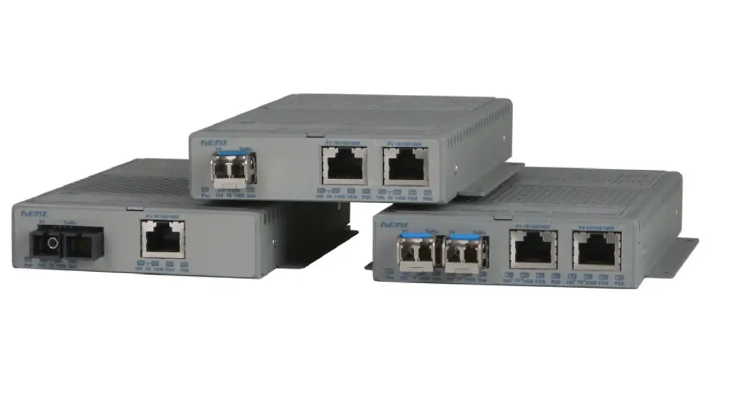
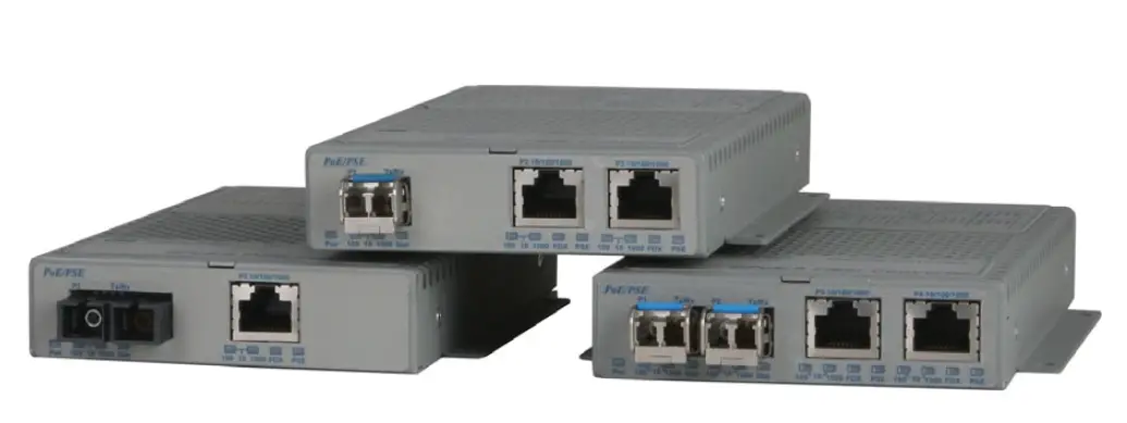
The OmniConverter GPoE/S and GPoE+/S are media converters that provide 10/100/1000BASE-T copper to 1000BASE-X or 100BASE-FX fiber conversion. They also function as Power-over-Ethernet (PoE) Power Sourcing Equipment (PSE) and support IEEE 802.3af PoE standard providing up to 15.4W of DC power to each PD, while the GPoE+/S supports IEEE 802.3at PoE+ standard providing up to 30W of DC power to each PD. Port configurations are available in single or dual RJ-45 and SFP ports.
Product Usage Instructions
To use the OmniConverter GPoE/S and GPoE+/S, follow the instructions below:
- Connect the media converter to an AC power source using the provided power adapter.
- Connect the media converter’s RJ-45 port(s) to the network device(s) using Ethernet cable(s).
- Connect the media converter’s fiber port(s) to the fiber optic network using fiber optic cable(s).
- If you want to connect a PD device to the converter, connect it to the RJ-45 port with the PoE+ capability.
- Ensure that the connected devices are powered on.
- If you encounter any problems during installation, contact Omnitron Technical Support (contact information provided in the user manual).
Remember to observe all safety warnings and cautions provided in the user manual, and dispose of the equipment properly in accordance with environmental regulations.
General and Copyright Notice
This publication is protected by U.S. and international copyright laws. All rights reserved. The whole or any part of this publication may not be reproduced, stored in a retrieval system, translated, transcribed, or transmitted, in any form, or by any means, manual, electric, electronic, electromagnetic, mechanical, chemical, optical or otherwise, without prior explicit written permission of Omnitron Systems Technology, Inc. The following trademarks are owned by Omnitron Systems Technology, Inc.: FlexPointTM, FlexSwitchTM, iConverter®, miConverterTM, NetOutlook®, OmniLight®, OmniConverter®, RuggedNet®, Omnitron Systems Technology, Inc.TM, OSTTM and the Omnitron logo. All other company or product names may be trademarks of their respective owners. The information contained in this publication is subject to change without notice. Omnitron Systems Technology, Inc. is not responsible for any inadvertent errors.
Warranty
This product is warranted to the original purchaser (Buyer) against defects in material and workmanship for a period of two (2) years from the date of shipment. A lifetime warranty may be obtained by the original purchaser by registering this product at www.omnitron-systems.com/support within ninety (90) days from the date of shipment. During the warranty period, Omnitron will, at its option, repair or replace a product that is proven to be defective with the same product or with a product with at least the same functionality. For warranty service, the product must be sent to an Omnitron-designated facility, at Buyer’s expense. Omnitron will pay the shipping charge to return the product to Buyer’s designated US address using Omnitron’s standard shipping method.
Limitation of Warranty
The foregoing warranty shall not apply to product malfunctions resulting from improper or inadequate use and/or maintenance of the equipment by the Buyer, Buyer-supplied equipment, Buyer-supplied interfacing, unauthorized modifications or tampering with equipment (including removal of equipment cover by personnel not specifically authorized and certified by Omnitron), or misuse, or operating outside the environmental specification of the product (including but not limited to voltage, ambient temperature, radiation, unusual dust, etc.), or improper site preparation or maintenance. No other warranty is expressed or implied. Omnitron specifically disclaims the implied warranties of merchantability and fitness for any particular purpose. The remedies provided herein are the Buyer’s sole and exclusive remedies. Omnitron shall not be liable for any direct, indirect, special, incidental, or consequential damages, whether based on contract, tort, or any legal theory.
Environmental Notices
The equipment covered by this manual must be disposed of or recycled in accordance with the Waste Electrical and Electronic Equipment Directive (WEEE Directive) of the European Community directive 2012/19/EU on waste electrical and electronic equipment (WEEE) which, together with the RoHS Directive 2015/863/EU, for electrical and electronic equipment sold in the EU after July 2019. Such disposal must follow national legislation for IT and Telecommunication equipment in accordance with the WEEE directive:
- Do not dispose of waste equipment with unsorted municipal and household waste.
- Collect equipment waste separately.
- Return equipment using the collection method agreed upon with Omnitron. The equipment is marked with the WEEE symbol shown to indicate that it must be collected separately from other types of waste. In the case of small items, the symbol may be printed only on the packaging or in the user manual. If you have questions regarding the correct disposal of equipment go to www.omniton-systems.com/support or e-mail Omnitron at [email protected].


Safety Warnings and Cautions
 ATTENTION: Observe precautions for handling electrostatic discharge-sensitive devices.
 WARNING: Potential damage to equipment and personal injury.
 WARNING: Risk of electrical shock.
Customer Support Information
If you encounter problems while installing this product, contact Omnitron Technical Support:
- Phone:
- (949) 250-6510
- Fax:
- (949) 250-6514
- Address:
- Omnitron Systems Technology, Inc. T38 esla Irvine, CA 92618, USA
- Email:
- URL:
Product Overview
The OmniConverter GPoE/S and GPoE+/S media converters with multi-port options provide 10/100/1000BASE-T copper to 1000BASE-X or 100BASE-FX fiber conversion and function as Power-over-Ethernet (PoE) Power Sourcing Equipment (PSE). Port configurations are available in single or dual RJ-45 and SFP ports. Equipment that provides DC power over twisted-pair cable is known as Power Sourcing Equipment (PSE). Equipment that is powered over a twisted-pair cable is known as a Powered Device (PD). The GPoE/S supports IEEE 802.3af PoE standard providing up to 15.4W of DC power to each PD. The GPoE+/S supports IEEE 802.3at PoE+ standard providing up to 30W of DC power to each PD.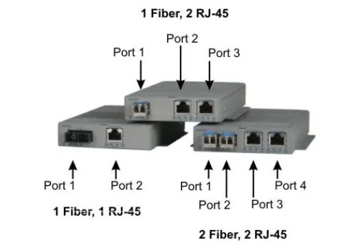
Installation Procedure
- Configure DIP-switches
- Install the Module
- Apply Power
- Connect Cables
- Verify Operation
Configure DIP-switches
DIP switches are located on the side of the module. The DIP switches are used to configure ports, link modes, and PoE/PSE options.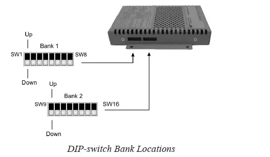
DIP-switch Bank Locations
The table below describes each DIP-switch position and function.
| Switch | 1 Fiber, 1 RJ-45 | 1 Fiber, 2 RJ-45 | 2 Fiber, 1 RJ-45 | 2 Fiber, 2 RJ-45 |
| 1 | Port 1 Fiber Speed | Port 1 Fiber Speed | Port 1 Fiber Speed | Port 1 Fiber Speed |
| 2 | N/A | N/A | Port 2 Fiber Speed | Port 2 Fiber Speed |
| 3 | Port 2 RJ-45 AUTO/MAN | Port 2 RJ-45 AUTO/MAN | Port 3 RJ-45 AUTO/MAN | Port 3 RJ-45 AUTO/MAN |
| 4 | Port 2 RJ-45 Speed (Only in MAN mode) | Port 2 RJ-45 Speed (Only in MAN mode) | Port 3 RJ-45 Speed (Only in MAN mode) | Port 3 RJ-45 Speed (Only in MAN mode) |
| 5 | Port 2 RJ-45 Duplex (Only in MAN mode) | Port 2 RJ-45 Duplex (Only in MAN mode) | Port 3 RJ-45 Duplex (Only in MAN mode) | Port 3 RJ-45 Duplex (Only in MAN mode) |
| 6 | Pause Capability | Pause Capability | Pause Capability | Pause Capability |
| 7 | RJ-45 Port 2 PoE/PSE | RJ-45 Port 2 PoE/PSE | RJ-45 Port 3 PoE/PSE | RJ-45 Port 3 PoE/PSE |
| 8 | N/A | RJ-45 Port 3 PoE/PSE | N/A | RJ-45 Port 4 PoE/PSE |
| 9 | PSE Configuration Type | PSE Configuration Type | PSE Configuration Type | PSE Configuration Type |
| 10 | PSE Configuration Type | PSE Configuration Type | PSE Configuration Type | PSE Configuration Type |
| 11 | N/A | N/A | PSE Configuration Type | PSE Configuration Type |
| 12 | Link Mode Selection | Link Mode Selection | Link Mode Selection | Link Mode Selection |
| 13 | Link Mode Selection | Link Mode Selection | Link Mode Selection | Link Mode Selection |
| 14 | PSE Reset | PSE Reset | PSE Reset | PSE Reset |
| 15 | N/A | N/A | Redundant Fiber Link | Redundant Fiber Link |
| 16 | N/A | N/A | Return to Port 1 | Return to Port 1 |
SW1 and SW2: F/O Speed “100/1000” DIP-switch
The module supports 1000BASE-X and 100BASE-FX SFPs. These DIP switches are used to configure the unit for the speed of the installed SFPs. Setting these DIP switches to the Down “1000” position enables the fiber port to accept 1000BASE-X SFPs. Setting these DIP switches to the Up “100” position enables the fiber port to accept 100BASE-FX SFPs. When an RJ-45 transceiver is installed in a SFP receptacle or for fixed fiber models, setting this DIP-switch to the Up “100” position enables the port to operate at 100Mbps*. These DIP switches are ignored when using Omnitron-branded fiber SFPs. The module automatically configures the fiber port to the correct speed. *Special compatibility mode for the fixed fiber models only.
SW3, SW4 and SW5 RJ-45 Configuration DIP-Switches
| SW3 RJ-45 AN/Man | SW4 RJ-45 100/10 | SW5 RJ-45 FDX/HDX | RJ-45 Mode of Operation |
| AN | 10 or 100 | FDX or HDX | The RJ-45 port is set to auto-negotiation with the following modes advertised: 1000FDX, 1000HDX, 100FDX, 100HDX, 10FDX, 10HDX |
| MAN | 100 | FDX | The RJ-45 port is set to manual negotiation and is forced to 100FDX. |
| MAN | 100 | HDX | The RJ-45 port is set to manual negotiation and is forced to 100HDX. |
| MAN | 10 | FDX | The RJ-45 port is set to manual negotiation and is forced to 10FDX. |
| MAN | 10 | HDX | The RJ-45 port is set to manual negotiation and is forced to 10HDX. |
SW6 – Pause “On/Off” DIP-Switch
In auto-negotiation mode, setting this DIP-switch to the Up “On” position allows the unit to advertise Symmetrical and Asymmetrical Pause capability. In auto-negotiation mode, setting the DIP-switch to the Down “Off” position allows the unit to advertise no Pause capability. In the manual mode, this DIP-switch determines the Pause behavior.
SW7 – Power Sourcing Function, RJ-45 Port
The OmniConverter automatically detects the attached PD and provides the equipment with the necessary power. This DIP-switch controls the power sourcing function for Port 2 on the single-fiber models and Port 3 on all other models (see DIP-switch Definition table on page 5). When this DIP-switch in the Down “On” position, the power sourcing function is enabled. When the DIP-switch is in the Up “Off” position, the power sourcing function is disabled.
| Switch Position | Description | DOWN | UP |
| 7 | RJ-45 Port 2 or 3 PoE/PSE | Enabled (ON) | Disabled (OFF) |
| 8 | RJ-45 Port 3 or 4 PoE/PSE | Enabled (ON) | Disabled (OFF) |
SW8 – Power Sourcing Function, RJ-45 Port
This DIP-switch controls the power sourcing function for the 2nd RJ-45 port on the 2 RJ-45 port models (see DIP-switch Definition table on page 5). When this DIP switch in the Down “On” position, the power sourcing function is enabled. When the DIP switch is in the “Off” UP position, the power sourcing function is disabled.
SW9, SW10 and SW11 – Power Sourcing Modes
The RJ-45 ports can be configured to support different powering modes. The powering modes include Alternative A (supporting power on pins 1,2 and 3,6), Alternative B (supporting power on pins 4,5 and 7,8), legacy Power Devices (PDs) that use large capacitance for detection (supporting pins 4,5 and 7,8), and legacy VoIP phones (supporting reverse polarity on pins 4,5 and 7,8).
| PoE Modes | ||||
| SW9 | SW10 | SW11 | 1 Fiber 1 RJ-45 | 2 Fiber 1 RJ-45 |
| Port 2 | Port 3 | |||
| DOWN | DOWN | N/A | IEEE Alt A | IEEE Alt A |
| UP | DOWN | N/A | IEEE Alt B | IEEE Alt B |
| DOWN | UP | N/A | Large Capacitor Detection | Large Capacitor Detection |
| UP | UP | N/A | Legacy VoIP | Legacy VoIP |
Power Sourcing Modes for Models with 1 RJ-45 Port
| PoE Modes | ||||||
| SW9 | SW10 | SW11 | 1 Fiber 2 RJ-45 | 2 Fiber 2 RJ-45 | ||
| Port 2 | Port 3 | Port 3 | Port 4 | |||
| DOWN | DOWN | DOWN | IEEE Alt A | IEEE Alt A | IEEE Alt A | IEEE Alt A |
| DOWN | DOWN | UP | IEEE Alt A | IEEE Alt B | IEEE Alt A | IEEE Alt B |
| DOWN | UP | DOWN | IEEE Alt B | IEEE Alt A | IEEE Alt B | IEEE Alt A |
| DOWN | UP | UP | IEEE Alt B | Legacy VoIP | IEEE Alt B | Legacy VoIP |
| UP | DOWN | DOWN | Large Capacitor Detection | IEEE Alt A | Large Capacitor Detection | IEEE Alt A |
| UP | DOWN | UP | Large Capacitor Detection | IEEE Alt B | Large Capacitor Detection | IEEE Alt B |
| DOWN | UP | UP | Legacy VoIP | IEEE Alt A | Legacy VoIP | IEEE Alt A |
| UP | UP | UP | Legacy VoIP | Legacy VoIP | Legacy VoIP | Legacy VoIP |
Power Sourcing Modes for Models with 2 RJ-45 Ports
Select the appropriate powering source option based on the PD type. Use the following table to determine the compatibility of the PD.
| PD Type | PSE Type | |||
| Alternative A | Alternative B | Large Capacitor | Legacy VoIP (Cisco) | |
| IEEE 802.3 af | Yes | Yes | Yes | No |
| IEEE 802.3 at* | Yes | Yes | Yes | No |
| Legacy VoIP Phones | No | No | No | Yes |
| Large Capacitor | No | No | Yes | No |
| *Requires FPoE+/S models | ||||
Power Sourcing Compatibility
| RJ-45 Pinout | PoE Modes | ||
| Alternative A | Alternative B | Legacy VoIP | |
| 1 | Vport Positive | ||
| 2 | Vport Positive | ||
| 3 | Vport Negative | ||
| 4 | Vport Positive | Vport Negative | |
| 5 | Vport Positive | Vport Negative | |
| 6 | Vport Negative | ||
| 7 | Vport Negative | Vport Positive | |
| 8 | Vport Negative | Vport Positive | |
Voltage Polarity for PoE Modes
NOTE: Alternative A and Alternative B pinouts are compliant with IEEE802.3af and IEEE802.3at specifications. Power is applied to center tap of transformers for both Alternative A and Alternative B pinouts per IEEE802.3at. Power is applied to the center tap of transformers for Legacy VoIP pinout, but the polarity is reversed.
SW12 and SW13 – Link Modes
The module supports Link Segment and Asymmetrical Link Propagate. See Appendix A for Link Mode block diagrams.
Link Segment
In Link Segment mode, all ports operate independently. A loss of a receive link signal will only affect the port detecting the loss of signal. All the other ports will continue to generate a link signal. A loss of link on the RJ-45 port will only affect the RJ-45 port, and the other ports will remain unaffected.
Asymmetrical Link Propagate
In Asymmetrical Link Propagate mode, faults are propagated based on the port notation. Port 1 to Port 2 notation indicates the direction the loss of link signal will propagate. A loss of receive link on the fiber optic Port 1 causes the RJ-45 Port 2 to drop its link due to the propagated state (Port 1 to Port 2). The loss of link on the RJ-45 Port 2 does not cause the loss of link to propagate. The loss only propagates in the Port 1 to Port 2 direction. See Port Configurations on Page 4.
Note: A loss of link or loss of signal is when the optical receiver on the media converter can no longer detect the presence of an optic signal.
Note: On models with 2 fiber ports or 2 RJ-45 ports, both ports of the same media type must be in link fault condition before the fault will propagate.
| SW12 | SW13 | Function |
| DOWN | DOWN | Link Segment (LS) |
| UP | DOWN | Asymmetrical Link Propagate Port 1 to Port 2 (1+1 – 2 Port models), Port 1 to Port 2 and Port 3 (1+2 – 3 Port models), Port 1 and Port 2 to Port 3 (2+1 – 3 Port models) and Port 1 and Port 2 to Port 3 and Port 4 (2+2 – 4 Port models). |
| DOWN | UP | Asymmetrical Link Propagate Port 2 to Port 1 (1+1 – 2 Port models), Port 2 and Port 3 to Port 1 (1+2 – 3 Port models) Port 3 to Port 1 and Port 2 (2+1 – 3 Port models) and Port 3 and Port 4 to Port 1 and Port 2 (2+2 – 4 Port models) |
| UP | UP | Invalid Configuration |
Link Modes
SW14 – Power Sourcing Reset
The OmniConverter can be configured to disable (reset) the PoE output power for 2 seconds after a loss of receive link on any fiber port. This feature is typically used to allow a PD to re-initialize after a failure on the incoming fiber. When this DIP-switch is in the Up “Lk Loss” position, the module will disable PoE output power for 2 seconds following a loss of receive link on any fiber port. When this DIP switch is in the Down position, PoE output power does not reset on fiber link loss.
SW15 and SW16 – Port Redundant Mode
SW15 and SW16 are valid on models with 2 fiber ports only. Port redundancy is available when connected to Omnitron and third-party devices with 2 fiber ports. SW15 controls the port redundancy mode of the module. When SW15 is in the Down “Off” (default) position, the fiber ports operate in a non-redundant (independent) mode. When SW15 is in the Up “On” position, the fiber ports operate as redundant links. A fault on the primary fiber port (Port 1), will cause a failover to the secondary fiber port (Port 2) within 50 msec. SW16 enables the module to return to the primary fiber port (Port 1) after the fiber link has been restored for 6 seconds. When SW16 is in the Down “Off” position, the return to primary is disabled (inactive). When the SW16 is in the Up “On” position, return to primary is enabled.
| Switch 15 P1+P2 Redun | Switch 16 Rtn P1 | Function |
| DOWN (Off) | DOWN (Off) | Non-redundant mode – normal mode |
| DOWN (Off) | UP (On) | Non-redundant mode – normal mode |
| UP (On) | DOWN (Off) | Redundant mode – no return to primary |
| UP (On) | UP (On) | Redundant mode – return to primary |
Port Redundancy Modes
Installing the Module
Wall Mounting
The wall mounting height of the module should be less than or equal to 2 meters (6.6 feet) from the floor. Use the four mounting holes on the module to secure the module to the wall. The module can accommodate #6 screws (not included). Installation of the module should be such that the air flow in the front, back, side and top vents of the switch are not compromised or restricted. The accessory cables should have their own strain relief and do not pull down on the module.
Rack Mounting
The module can be rack mounted using the optional Rack Mount Shelf (8260-0). Refer to the Rack Mount Shelf user manual (040-08260-001x) for the proper installation guidelines.
Follow the same guidelines above when rack mounting the module.
DIN-rail Mounting
The module can be DIN-rail mounted using the optional DIN-rail Mounting Bracket (8250-0) or the optional DIN-rail Mounting Clip (8251-0). Refer to the user manuals (040-08250-001x or 040-08251-001x) for the proper installation guidelines.
Apply Power
AC Power
Secure the ground wire to the NEBS grounding screw located on the back of the module. To power the unit using the AC/DC adapter, route the power cord through the provided strain relief for additional support. Then connect the barrel connector at the end of the wire on the AC/DC adapter to the 2.1mm DC barrel connector (center-positive) on the unit. Connect the AC/DC adapter to the AC outlet. Confirm that the module has powered up properly by checking the Power LED located on the front of the installed module. Installation of the equipment should be such that the airflow in the front, back, side and top vents of the chassis are not compromised or restricted.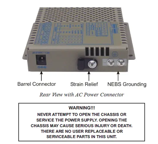
DC Power
This module is intended for installation in restricted access areas. (“Les matériels sont destinés à être installés dans des EMPLACEMENTS À ACCÈS RESTREINT”). A restricted access area can be accessed only through the use of a special key, or other means of security. The over-current protection for connection with centralized DC shall be provided in the building installation and shall be a UL-listed circuit breaker rated 20 Amps, and installed per the National Electrical Code, ANSI/NFPA-70. Appropriate overloading protection should be provided on the DC power source outlets utilized. The GPoE/S requires 46 to 57VDC @ 0.79 Amp max rated power. The GPoE+/S this equipment requires 52 to 57VDC @ 1.37 Amp max rated power (see Specification table for specific model requirements).
| Description | IEEE 802.3af PoE | IEEE 802.3at PoE+ |
| Power Supply Voltage Range | 46.0 to 57.0 VDC | 51.0 to 57.0 VDC |
| Voltage Range at PSE port Output | 44.0 to 56.0 VDC | 50.0 to 56.0 VDC |
| Maximum Power from PoE/PSE port | 15.4 watts | 30 watts |
| Minimum Voltage at PoE/PD port input* | 37.0 VDC | 42.5 VDC |
| Minimum Power at PoE/PD port* | 12.95 watts | 25.5 watts |
| * at 100 meters using Cat5 | ||
WARNING: Only a DC power source that complies with safety extra low voltage (SELV) requirements can be connected to the DC-input power supply
WARNING REGARDING EARTHING GROUND:
- This equipment shall be connected to the DC supply system earthing electrode conductor or to a bonding jumper from an earthing terminal bar or bus to which the DC supply system earthing electrode is
- This equipment shall be located in the same immediate area (such as adjacent cabinets) as any other equipment that has a connection between the earthed conductor of the same DC supply circuit and the earthing conductor, and also the point of earthing of the DC The DC system shall not be earthed elsewhere.
- The DC supply source is to be located within the same premises as this
- There shall be no switching or disconnecting devices in the earthed circuit conductor between the DC source and the earthing electrode
Locate the DC circuit breaker of the external power source, and switch the circuit breaker to the OFF position. Prepare a power cable using a three-conductor insulated wire (not supplied) with 12AWG to 14AWG thickness. Cut the power cable to the length required. Strip approximately 3/8 of an inch of insulation from the power cable wires. Connect the ground wire to the NEBS grounding screws on the back of the module. Route the power cables through the provided strain relief for additional support. Connect the power cables to the module by fastening the stripped ends to the DC power connector.
WARNING: Note the wire colors used in making the positive, negative, and ground connections. Use the same color assignment for the connection at the circuit breaker. Connect the power wires to the circuit breaker and switch the circuit breaker ON. If any modules is installed, the Power LED will indicate the presence of power. During the installation, ensure that the ground potentials are maintained throughout the system connections. This includes but is not limited to the power source ground and any shielded cabling grounds. Installation of the equipment should be such that the airflow in the front, back, side, and top vents of the chassis are not compromised or restricted.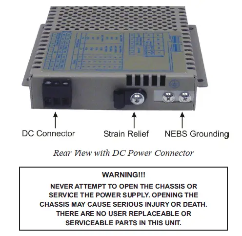
Connect Cables
- When using the SFP model, insert the SFP Fiber transceiver into the SFP receptacle on the front of the module (see the SFP Data Sheet 091-17000-001 for supported Gigabit and Fast Ethernet transceivers).
NOTE: The release latch of the SFP Fiber transceiver must be in the closed (up) position before insertion. - Connect an appropriate multimode or single-mode fiber cable to the fiber port on the front of the module. It is important to ensure that the transmit (TX) is attached to the receive side of the device at the other end and the receiver (RX) is attached to the transmit side. When using single-fiber (SF) models, the TX wavelength must match the RX wavelength at the other end and the RX wavelength must match the TX wavelength at the other end.
- Connect the Ethernet 10/100/1000 RJ-45 port via a Category 5 or better cable to an external 10BASE-T, 100BASE-TX or 1000BASE-T Ethernet device.
Verify Operation
Verify the module is operational by viewing the LED indicators.
| Power LED Indicators | ||
| Legend | Indicator | Description |
| Pwr | OFF | Unit not powered |
| Green – ON | Unit powered | |
| Amber – ON | Over temperature condition | |
Power LED Indicators
| Fiber Port LED Indicators | ||
| Legend | Indicator | Description |
|
100 | OFF | No link |
| Green – ON | Port linked at 100Mbps | |
| Green – Blinking at 10Hz | Port data activity at 100Mbps | |
| Green – Blinking at 1Hz | Port linked at 100Mbps and in redundant standby mode | |
| Amber – Blinking at 1Hz | Port linked at 100Mbps and receiving Far End Fault Indicator (FEFI) | |
|
1000 | OFF | No link |
| Green – ON | Port linked at 1000Mbps | |
| Green – Blinking at 10Hz | Port data activity at 1000Mbps | |
| Green – Blinking at 1Hz | Port linked at 1000Mbps and in redundant standby mode | |
| Amber – Blinking at 1Hz | Port linked at 1000Mbps and receiving AN Remote Fault | |
|
10 (100+1000) | OFF | No link |
| Green – ON | Port linked at 10Mbps | |
| Green – Blinking at 10Hz | Port data activity at 10Mbps | |
| Green – Blinking at 1Hz | Port linked at 10Mbps and in redundant standby mode | |
|
Stat | OFF | Transceiver does not support digital diagnostics or no transceiver (SFP) is installed |
| Green – ON | Transceiver (SFP) supports digital diagnostics and no alarm is detected | |
| Amber – ON | Transceiver (SFP) supports digital diagnostics and alarms are present | |
Fiber LED Indicators
| RJ-45 Port Indicators | ||
| Legend | Indicator | Description |
| 100 | OFF | No link |
| Green – ON | Port linked at 100Mbps | |
| Green – Blinking at 10Hz | Port data activity at 100Mbps | |
| 1000 | OFF | No link |
| Green – ON | Port linked at 1000Mbps | |
| Green – Blinking at 10Hz | Port data activity at 1000Mbps | |
|
10 (100+1000) | OFF | No link |
| Green – ON | Port linked at 10Mbps | |
| Green – Blinking at 10Hz | Port data activity at 10Mbps | |
| Amber – Blinking at 1Hz | Port linked at 10Mbps and receiving AN Remote Fault | |
|
FDX | Green – ON | Port is configured for full-duplex via DIP-switch or has negotiated to full-duplex in AN mode |
| OFF | Port is configured for half-duplex via DIP-switches or Port 2 has negotiated to half-duplex in AN mode or Port 2 in AN mode has not established the correct connection | |
|
PSE | Green – ON | Port PSE is active |
| Amber – ON | Port PSE inactive | |
| Amber – Blinking at 1Hz | Port PSE inactive due to resistance too low (< 15k ohms) or short circuit detected | |
| Amber – Blinking at 10Hz | Port PSE inactive due to resistance to high (33k to 500k ohms) | |
| OFF | Port PSE disabled | |
RJ-45 LED Indicators
Specifications
| AC/DC Adapter Temperature Derating Total Available Wattage to RJ-45 Ports | |||||||
| Model | RJ-45 Ports | Watts Required | 40°C | 50°C | 60°C | 70°C | 75°C |
| GPoE/S | 1 | 15 watts | Full Power | Full Power | Full Power | Full Power | Full Power |
| 2 | 30 watts | Full Power | Full Power | Full Power | Full Power | Full Power | |
| GPoE+/S | 1 | 30 watts | Full Power | Full Power | Full Power | Full Power | Full Power |
| 2 | 60 watts | Full Power | Full Power | Full Power | Full Power | 50 watts | |
The AC/DC Adapter Temperature derating table does not apply to models with DC Terminal. The DC Terminal models will provide full PoE power over the operating temperature range of the module as long as the DC input power meets the requirements stated in the specification table.
| Description | OmniConverter GPoE/S 10/100/1000BASE-T to 1000BASE-X or 100BASE-X Fiber Media Converter with PoE | |
| Standard Compliances | IEEE 802.3, IEEE 802.3af (15.40 watts max) | |
| PoE Supported Modes | IEEE Alternate A (Alt A), IEEE Alternate B (Alt B), Cisco Legacy and High Cap | |
| Environmental | RoHS, WEEE and REACH | |
| Frame Size | Up to 10,240 bytes | |
|
Port Types | Copper: 10/100/1000BASE-T (RJ-45) Fiber: 100BASE-X (SFP) 1000BASE-X (ST, SC, LC, SFP) 1000BASE-BX (SC, SFP) | |
| Cable Types | Copper: EIA/TIA 568A/B, Cat 5 UTP and higher Fiber: Multimode: 50/125, 62.5/125µm Single-mode: 9/125µm | |
| AC Power Requirements (Models with AC/DC Adapters) | 1 RJ-45 Port 100 – 240VAC/47 to 63Hz 0.21A @ 120VAC (typical) | 2 RJ-45 Ports 100 – 240VAC/50 – 60Hz 0.36A @ 120VAC (typical) |
| DC Power Requirements (Models with DC Terminals) | 1 RJ-45 Port +/-46 to +/-57VDC; 0.46A @ 48VDC 3 Pin Terminal (isolated) | 2 RJ-45 Ports +/-46 to +/-57VDC; 0.79A @ 48VDC 3 Pin Terminal (isolated) |
| Dimensions (W x D x H) | 4.5” x 6.0” x 1.0” (114.3 mm x 152.4 mm x 25.4 mm) | |
| Weight | Module Only: 1.1 lbs. (498.9 grams) Module w/ Adapter: 1.6 lbs. (725.7 grams) | |
| Operating Temperature (See Temperature Derating Table) | Commercial: 0 to 50°C Wide: -40 to 60°C (-20°C AC cold start) Extended: -40 to 75°C (-20°C AC cold start) Storage: -40 to 80°C | |
| Humidity | 5 to 95% (non-condensing) | |
| Altitude | -100m to 4,000m | |
| MTBF (hours) | Module Only: 474,000 AC/DC Adapter: 100,000 | |
| Warranty | Lifetime warranty with 24/7/365 free Technical Support | |
| Description | OmniConverter GPoE+/S 10/100/1000BASE-T to 1000BASE-X or 100BASE-X Fiber Media Converter with PoE+ | |
| Standard Compliances | IEEE 802.3, IEEE 802.3af (15.40 watts max), IEEE 802.3at (30 watts max) | |
| PoE Supported Modes | IEEE Alternate A (Alt A), IEEE Alternate B (Alt B), Cisco Legacy and High Cap | |
| Environmental | RoHS, WEEE and REACH | |
| Frame Size | Up to 10,240 bytes | |
|
Port Types | Copper: 10/100/1000BASE-T (RJ-45) Fiber: 100BASE-X (SFP) 1000BASE-X (ST, SC, LC, SFP) 1000BASE-BX (SC, SFP) | |
| Cable Types | Copper: EIA/TIA 568A/B, Cat 5 UTP and higher Fiber: Multimode: 50/125, 62.5/125µm Single-mode: 9/125µm | |
| AC Power Requirements (Models with AC/DC Adapters) | 1 RJ-45 Port 100 – 240VAC/47 to 63Hz 0.34A @ 120VAC (typical) | 2 RJ-45 Ports 100 – 240VAC/50 – 60Hz 0.63A @ 120VAC (typical) |
|
DC Power Requirements (Models with DC Terminals) | 1 RJ-45 Port +/-48 to +/-57VDC; 0.74A @ 48VDC 3 Pin Terminal (isolated) | 2 RJ-45 Ports +/-48 to +/-57VDC; 1.37A @ 48VDC 3 Pin Terminal (isolated) |
| A minimum DC input voltage of 50VDC is required to guarantee 25.5 watts (for 802.3at) at the end of 100 meters on Cat 5 cable or better. | ||
| Dimensions (W x D x H) | 4.5” x 6.0” x 1.0” (114.3 mm x 152.4 mm x 25.4 mm) | |
| Weight | Module Only: 1.1 lbs. (498.9 grams) Module w/ Adapter: 2.3 lbs. (1043.3 grams) | |
| Operating Temperature (See Temperature Derating Table) | Commercial: 0 to 50°C Wide: -40 to 60°C (-20°C AC cold start) Extended: -40 to 75°C (-20°C AC cold start) Storage: -40 to 80°C | |
| Humidity | 5 to 95% (non-condensing) | |
| Altitude | -100m to 4,000m | |
| MTBF (hours) | Module Only: 474,000 AC/DC Adapter: 100,000 | |
| Warranty | Lifetime warranty with 24/7/365 free Technical Support | |
| Safety: | UL 62368-1*, UL 60950-1, IEC 62368-1*, IEC 60950-1, EN 62368-1*, EN 60950-1, CAN/CSA C22.2 No. 62368-1-14*, CAN/CSA C22.2 No. 60950-1, CE Mark | |
| EMC: | EN 55032/EN 55024 CE Emissions/Immunity | |
| Regulatory Compliances (* Pending) | EMI: EMS: | CISPR 32, FCC 47 Part 15 Subpart B Class A IEC 61000-4-2 ESD: Contact: 6 kV; Air: 8 kV, IEC 61000-4-3 RS: 80 MHz to 1 GHz: 3 V/m, IEC 61000-4-4 EFT: Power: 2 kV; Signal: 1 kV (DC models), IEC 61000-4-4 EFT: Power: 1 kV; Signal: 1 kV (AC models), IEC 61000-4-5 Surge: Power: 2 kV; Signal: 2 kV (DC models), IEC 61000-4-5 Surge: Power: 1 kV Line/Line; 2 kV Line/Gnd; Signal: 2 kV (AC models), IEC 61000-4-6 CS: Signal: 3 V, IEC 61000-4-8 ( Magnetic Field) 30A/m, IEC 61000-4-11 (Voltage Dips, interrupts) |
| IP Rating: | IP20 Protection |
Appendix A: Link Modes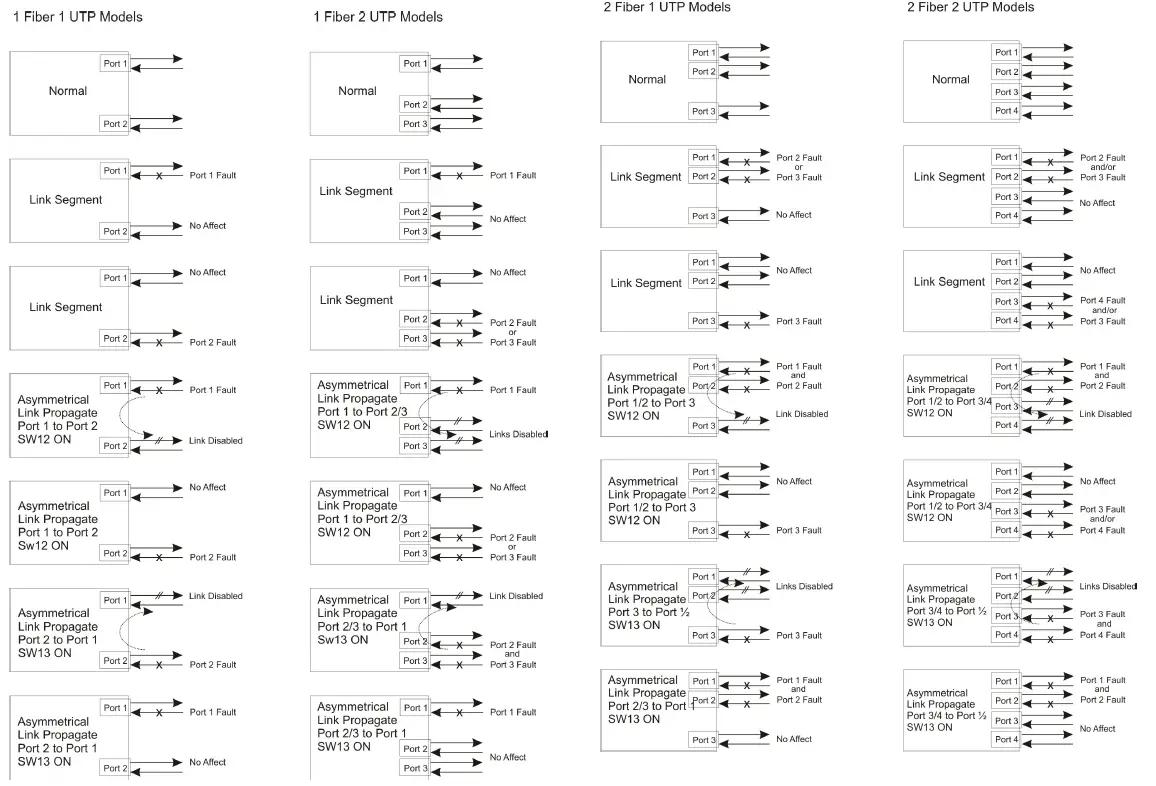


 Media Converter User Manual")


