
![]() POE 10 Cable Tester
POE 10 Cable Tester
User Manual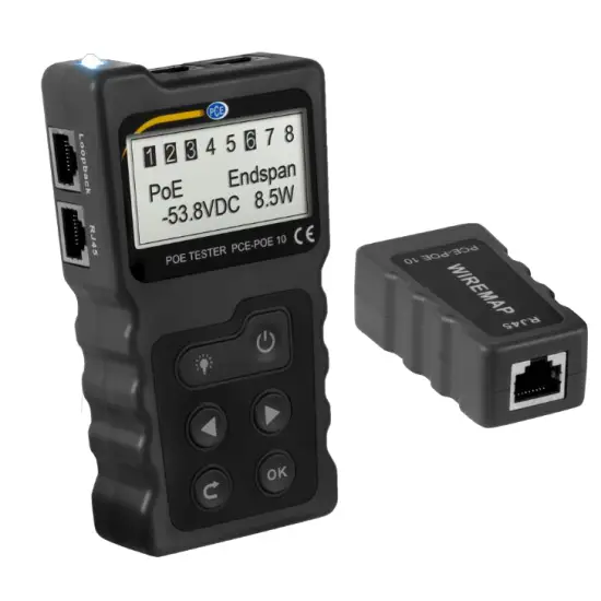
User manuals in various languages
 http://www.pce-instruments.com
product search on: www.pce-instruments.com
Safety notes
Please read this manual carefully and completely before you use the device for the first time. The device may only be used by qualified personnel and repaired by PCE Instruments personnel. Damage or injuries caused by non-observance of the manual are excluded from our liability and not covered by our warranty.
- The device must only be used as described in this instruction manual. If used otherwise, this can cause dangerous situations for the user and damage to the meter.
- The instrument may only be used if the environmental conditions (temperature, relative humidity, …) are within the ranges stated in the technical specifications. Do not expose the device to extreme temperatures, direct sunlight, extreme humidity, or moisture.
- Do not expose the device to shocks or strong vibrations.
- The case should only be opened by qualified PCE Instruments personnel.
- Never use the instrument when your hands are wet.
- You must not make any technical changes to the device.
- The appliance should only be cleaned with a damp cloth. Use only pH-neutral cleaner, no abrasives or solvents.
- The device must only be used with accessories from PCE Instruments or equivalent.
- Before each use, inspect the case for visible damage. If any damage is visible, do not use the device.
- Do not use the instrument in explosive atmospheres.
- The measurement range as stated in the specifications must not be exceeded under any circumstances.
- Non-observance of the safety notes can cause damage to the device and injuries to the user.
We do not assume liability for printing errors or any other mistakes in this manual.
We expressly point to our general guarantee terms which can be found in our general terms of business.
If you have any questions please contact PCE Instruments. The contact details can be found at the end of this manual.
Specifications
| Transmitter specifications | ||
| Display | LC display 128 x 64 mm with backlight | |
| Continuity test | Cable types | STP and UTP |
| Maximum cable length | 600 m | |
| Connection type | Transmitter + remote control | |
| Transmitter + switch/ router | ||
| PoE functions | Measurement range | DC 5 … +60 V POE switch |
| Standard identifier | 802.3af/at (standard /no standard) | |
| Power measurement range | 0 … 18 W | |
| Measurement functions | Voltage measurement range | DC 0 … +60 V |
| Current measurement range | 0 … +3 A | |
| Power measurement range | 0 … 180 W | |
| Max. input power | DC 48 V 5 mA | |
| Max. Input current | 580 mA | |
| Loop-back test | Compatible with 10M, 100M, 1000M switch | |
| Power supply | 3 x 1.5 V AAA batteries | |
| Receiver specifications | ||
| Connection | RJ45 | |
| Function | Cable test functions | |
Delivery scope
1 x PCE-POE 10 transmitter
1 x PCE-POE 10 receiver
3 x 1.5 V AAA battery
1 x RJ45 test cable
1 x RJ11 test cable
1 x RJ11 test adaptor with alligator clip
1 x user manual
1 x transport bag
Device description
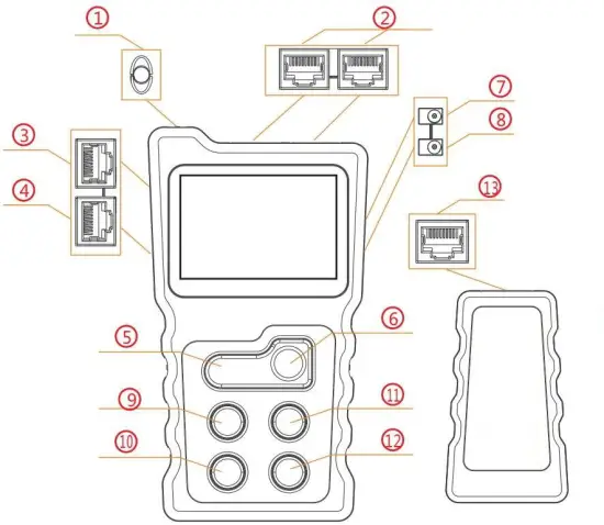
| 1. Light | 8. DC In |
| 2. PoE test connection | 9. Arrow key left |
| 3. RJ-45 loopback connector | 10. Back key |
| 4. RJ-45 connector for cable test functions | 11. Arrow key right |
| 5. Light ON/OFF | 12. OK |
| 6. On/off switch | 13.RJ45 connection for cable test functions |
| 7. DC Out |
Main menu
POE: POE switch test and POE performance test
CONT: Cable test functions
POWER: Voltage and current measurement between the PSE and the PD and calculation of the power consumption
LOOP: Perform loop back test
SET: Setting of language, backlight time, automatic power-off, display contrast, and display of the software version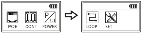 PoE switch test
Connect a network cable between the PoE switch and the PCE-POE 10 (RJ45 connection 2, see above). The correct connection is signaled by means of the measured voltage on the display of the PCE-POE 10. Press “Enter” to start the test. The result is then displayed on the screen.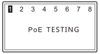 Standard PoE switch:
If the PoE switch being tested is a standard PoE switch, the test result is displayed as follows: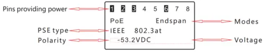
Non-standard PoE switch:
If the PoE switch being tested is a non-standard PoE switch, the test result is displayed as follows:
Connect Error
If the error message “Connect Error” appears, it is possible that additional POE end devices are connected to the POE switch to be tested. Disconnect the cable connection of these devices and repeat the test.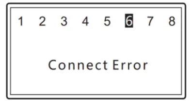
Unconnected
If the error message “Unconnected” appears on the display, no compatible POE switch has been detected.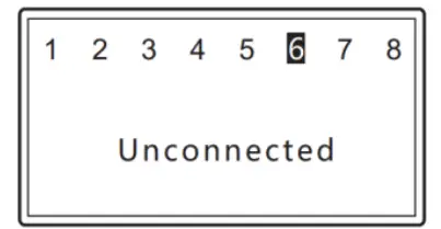
PoE power test
For the PoE power test, a PoE switch and a PoE end device (e. g. PoE camera) must be connected to the PCE-POE 10. After a successful connection, a voltage value is displayed on the screen. A few seconds later, the meter automatically switches to the power test. The display information is shown in the following picture.
As soon as all measured power parameters are displayed, you can start the identification of the PSE by pressing the Enter key. If the message “Non-Standard” appears on the display, the connected PSE does not comply with the current standards; if no message appears on the display, the connected PSE complies with the current standards. 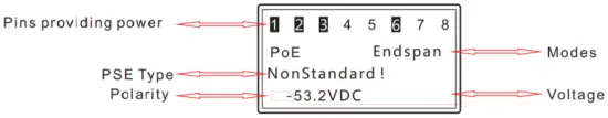
Cable test functions
This function can be used to find short circuits, open and crossed wire pairs in the connected network cable. To do this, connect the network cable to be tested to the RJ45 connector 4 and the receiver supplied to the other end of the cable.
The connected network cable can be an 8-core UTP or a 9-core STP network cable.
If the cables are intact, one of the following screens will appear on the PCE-POE 10:
Short circuit
If a short circuit is detected in the connected cable, the following appears on the display of the PCE-POE 10 (example):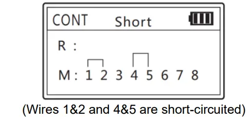
Open wire pairs
If the PCE-POE 10 detects open-wire pairs in the connected network cable, the following screen is displayed (example):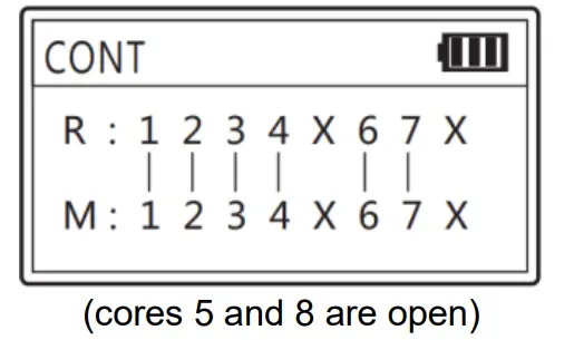
Crossed wire pairs
If crossed wire pairs are detected in the connected network cable, the following appears on the display of the PCE-POE 10 (example):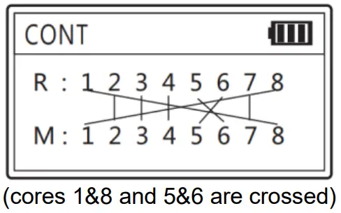
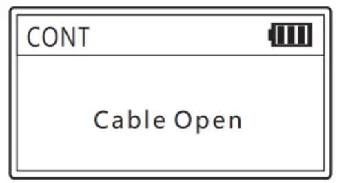
Cable open
If the message “Cable open” appears on the display of the PCE-POE 10, this may be due to the following reasons:
- The connected network cable actually has a breakage.
- The connected network cable is not correctly connected to the transmitter.
- The connected network cable is not correctly connected to the receiver.

Power test function
This function can be used to measure the power consumption of the PSE or PD. To do so, use sockets 7 and 8 on the right-hand side of the PCE-POE 10. The main adaptor of the PSE or PD is connected to the “DC IN” input and the PSE or PD itself to the “DC OUT” output.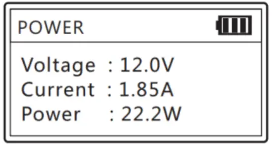
Loop-back test
The loopback test can be used to test individual ports on a switch or end device. The PCE-POE 10 sends data packets and attempts to receive them again at the same time. If the test is successful, the status LEDs on the port to be tested light up. Connect a network cable to the loopback connector of the PCE- POE 10 and to the port to be tested.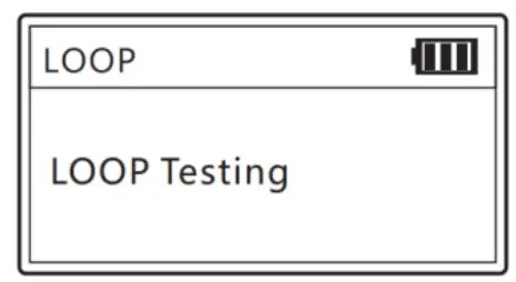
Lighting function
Press the light key to switch the LED on or off.
Settings
Language
At present, the menu navigation of the unit is only available in English.
Backlight
The backlight time can be set between 15 s, 30 s, 60 s, On and Off.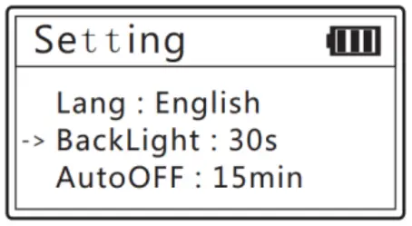
Automatic power-off
The automatic power-off of the meter can be set at intervals of 15, 30, and 60 minutes or disabled by selecting “off”.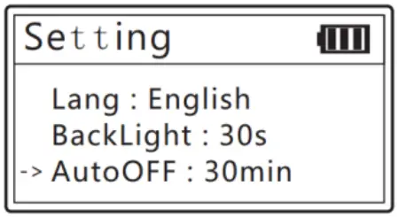
Display contrast
The display contrast can be changed between 20 and 35 with the arrow keys.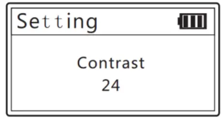
Software version
This menu item displays the hardware/software version of the unit.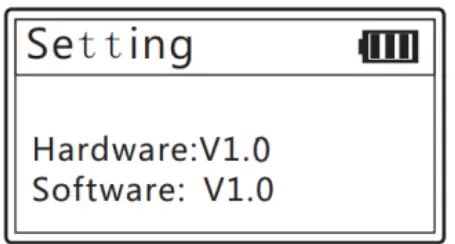
Warranty
You can read our warranty terms in our General Business Terms which you can find here: https://www.pce-instruments.com/english/terms.
Disposal
For the disposal of batteries in the EU, the 2006/66/EC directive of the European Parliament applies. Due to the contained pollutants, batteries must not be disposed of as household waste.
They must be given to collection points designed for that purpose.
In order to comply with the EU directive 2012/19/EU, we take our devices back. We either re-use them or give them to a recycling company that disposes of the devices in line with the law.
For countries outside the EU, batteries, and devices should be disposed of in accordance with your local waste regulations.
If you have any questions, please contact PCE Instruments.

References
 France.fr : Actualités, destinations et infos du tourisme en France
-
iberica.es
-
instruments.cn
 Make an offer on the domain instruments.co.uk - Domains.co.uk
-
Computer Instruments | Home
 Discover Italy: Official Tourism Website - Italia.it
 PCE(北京)科技有限公司
-
Industrial Measurement Products and Solutions | PCE Instruments
-
PCE Deutschland GmbH Prüfgeräte vom Hersteller | PCE Instruments
-
PCE Brookhuis B.V. | PCE Instruments
-
PCE Americas Inc. : Test Instruments | PCE Instruments
-
PCE Iberica S.L. Instrumentación | PCE Instruments
-
PCE Instruments France | PCE Instruments
-
PCE Italia s.r.l. / Strumenti di Misura | PCE Instruments
-
PCE Teknik Cihazlar Paz. Tic. Ltd.Şti. | PCE Instruments
-
PCE Americas Inc. : Test Instruments | PCE Instruments


