![]() 0554 9330 LAN PoE Communication Module
0554 9330 LAN PoE Communication Module
Instruction Manual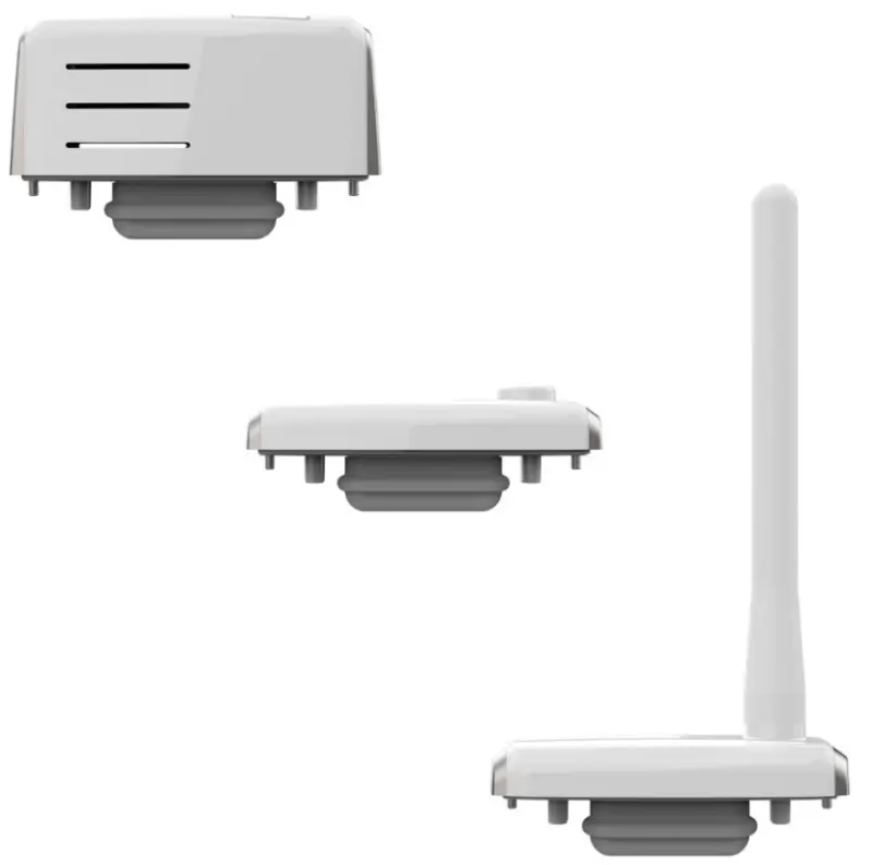
0554 9330 LAN PoE Communication Module
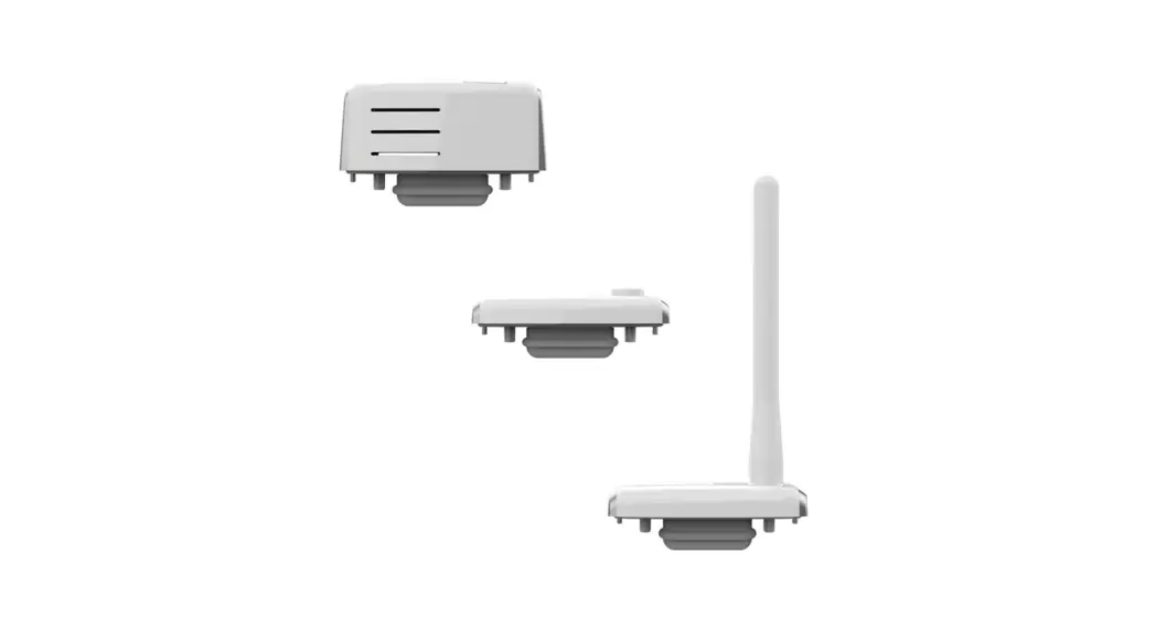
LAN/PoE communication module 0554 9330
WLAN communication module 0554 9320 01 testo
UltraRange communication module
0554 9311 01 / 0554 9311 02
0554 9312 01 / 0554 9312 02
0554 9313 01 / 0554 9313 02
0554 9314 01 / 0554 9314 02
Instruction manual
About this document
- The instruction manual is an integral part of the test Saveris measurement data monitoring system.
- Keep this documentation to hand so that you can refer to it when necessary.
- Please read this instruction manual carefully and familiarize yourself with the product before putting it to use.
- Hand this instruction manual on to any subsequent users of the product.
- The instruction manual for the test Saveris measurement data monitoring system is divided into the following sub-documents:
- Operating instructions for the test Saveris measurement data monitoring system
- Commissioning instructions for the test Saveris measurement data monitoring system
- Operating instructions for individual system components
- Pay particular attention to the safety instructions and warning advice in order to prevent injury and damage to the product.
- Familiarity with a PC as well as the Microsoft® products is assumed in this documentation.
Symbols and writing standards
Display | Explanation | |
| Note: basic or further information. | ||
| 1. 2. | … … | Action: several steps, the sequence must be followed. |
| · … | List | |
| > | … | Action: one step or optional step. |
| – | … | Result of an action. |
| ✓ … | Requirement | |
| 1… | Position numbers for the clarification of the relationship | |
| 2… | between text and picture. | |
| Menu | Elements of the instrument, the instrument display or the program interface. | |
| [OK] | Control keys of the instrument or buttons of the program interface. | |
| … | … | Functions/paths within a menu. |
| “…” | Example entries |
Safety and disposal
Take the test information document into account (accompanies the product).
Product-specific approvals
Please find the current country approvals in the enclosed Approvals and Certifications document.
Support
You can find up-to-date information on products, downloads and links to contact addresses for support queries on the Testo website at: www.testo.com.
Lieferumfang
- Communication module
- Instruction manual
- Testo information
- Approvals and Certifications
LAN/PoE1 communication module
6.1 Use
The LAN/PoE communication module for the test 150 data logger module is designed to transmit measurement data and to supply power via a LAN infrastructure. The product is used in the monitoring of products subject to cold chain requirements in warehouses, production facilities, cold rooms, clinics, laboratories and laboratory equipment. The product can only be used with other Testo components. Use of the product requires skilled personnel trained in the above areas. If the network ports used are PoE-enabled, power can be supplied to a connected testo 150 data logger module via the Ethernet cable.
6.2 Product Description
Overview
Power over Ethernet 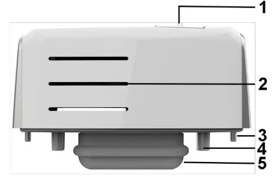
| 1 | Ethernet/PoE connection | 2 | Ventilation slits |
| 3 | Fastening screws | 4 | Positioning aid |
| 5 | TCI2 connector |
6.3 Commissioning
Attaching the communication module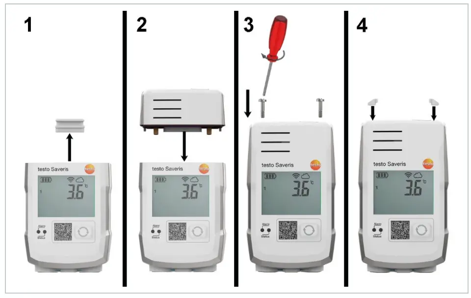
- Remove the protective cap.
- Place the communication module on the testo 150 data logger module.
- Attach the communication module to the testo 150 data logger module using the screws.
- Close screw openings with rubber plugs.
![]() It is not possible to replace communication modules while the testo 150 data logger module is in operation! To replace a communication module, the power supply must be disconnected (remove batteries/pull out mains plug).
It is not possible to replace communication modules while the testo 150 data logger module is in operation! To replace a communication module, the power supply must be disconnected (remove batteries/pull out mains plug).![]() Once the communication modules have been installed, the testo 150 data logger module can be returned to its original packaging.
Once the communication modules have been installed, the testo 150 data logger module can be returned to its original packaging.
6.4 Technical data for the LAN/PoE communication module
PoE performance class 0……………..max. 7 W
| Feature | Value |
| Order no. | 0554 9330 |
| Connections | TCI LAN/PoE |
| Dimensions (W x H x L) | 69.3 x 17.7 x 29.0 mm |
| Weight | Approx. 45 g |
| Protection class | IP30 with mounted testo 150 data logger module |
| Housing material | PC/PET (front); ABS+PC+10% GF/PET (rear) |
| Communication cycle | 5 seconds – 24 hours |
| Storage temperature | -35 °C to 60 °C |
| Operating temperature | -35 °C to 50 °C |
WLAN communication module
7.1 Use
The WLAN communication module for the testo 150 data logger module is designed for the wireless transmission of measurement data. The product is used in the monitoring of products subject to cold chain requirements in warehouses, production facilities, cold rooms, clinics, laboratories and laboratory equipment.
The product can only be used with other Testo components. Use of the product requires skilled personnel trained in the above areas.
7.2 Product Description
Overview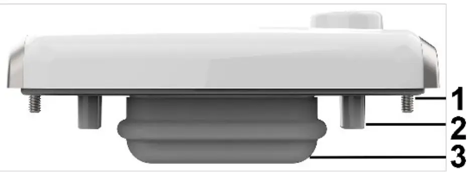
- Fastening screws
- Positioning aid
- TCI connector
7.3 Commissioning
Attaching the communication module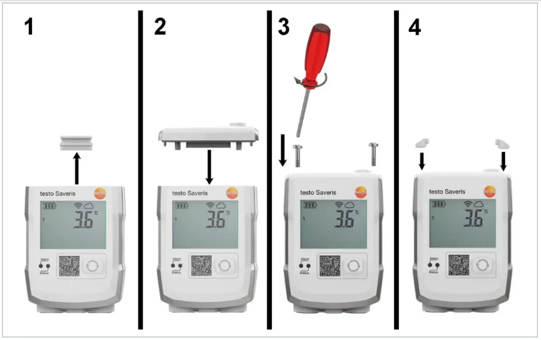
- Remove the protective cap.
- Place the communication module on the testo 150 data logger module.
- Attach the communication module to the testo 150 data logger module using the screws.
- Close screw openings with rubber plugs.
![]() It is not possible to replace communication modules while the testo 150 data logger module is in operation! To replace a communication module, the power supply must be disconnected (remove batteries/pull out mains plug).
It is not possible to replace communication modules while the testo 150 data logger module is in operation! To replace a communication module, the power supply must be disconnected (remove batteries/pull out mains plug).![]() Once the communication modules have been installed, the testo 150 data logger module can be returned to its original packaging.
Once the communication modules have been installed, the testo 150 data logger module can be returned to its original packaging.
7.4 Technical data for WLAN module
| Feature | Value |
| Order no. | 0554 9320 01 |
| Connections | TCI |
| Dimensions (W x H x L) | 69.3 x 9.5 x 29.0 mm |
| Weight | Approx. 17 g |
| Protection class | IP67 with mounted testo 150 data logger module |
| Housing material | PC/PET (front); ABS+PC+10% GF/PET (rear) |
| Communication cycle | 1 min to 24 h |
| Storage temperature | -40 °C to 60 °C |
| Operating temperature | -40 °C to 50 °C |
Testo UltraRange communication module
8.1 Use
A test UltraRange communication module with testo UltraRange radio technology is designed for the wireless transmission of measurement data.
UltraRange communication modules are designed either for combination with testo 150 data logger modules or with the UltraRange Gateway. Use of the product requires skilled personnel trained in the above areas.
An UltraRange Gateway is required to transmit data to the Saveris base when testo 150 data logger modules are combined with UltraRange communication modules.
Select the appropriate regional version of the testo UltraRange communication module depending on the intended region of use.
Products of this type are generally not suitable for outdoor use when delivered. Prerequisites for outdoor use are measures that reliably protect the product from environmental influences (e.g. moisture, solar radiation). Please note that measures to protect the product from environmental influences may impair its performance.
8.2 Product Description
Overview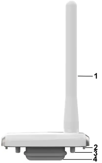
- Radio antenna
- Fastening screws
- Positioning aid
- TCI connector
8.3 Commissioning
Attaching the communication module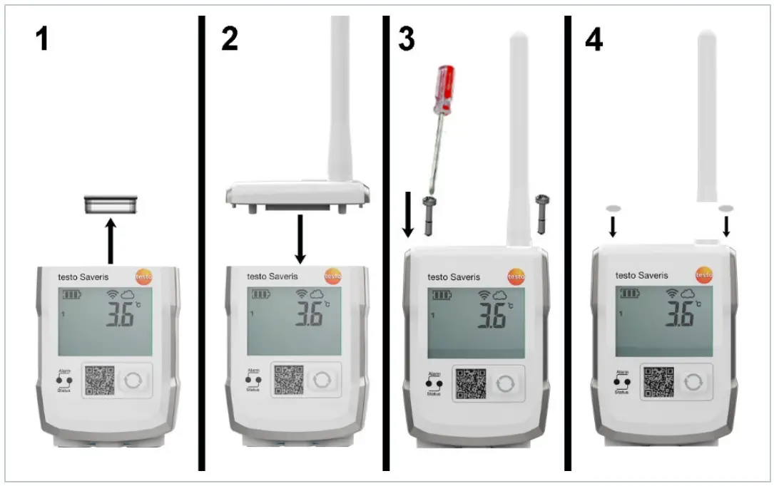
- Remove the protective cap.
- Place the communication module on the testo 150 data logger module.
- Attach the communication module to the testo 150 data logger module using the screws.
- Close screw openings with rubber plugs.
![]() When using wireless modules with an external antenna, please ensure that the screw connection between the antenna and module has been tightened.
When using wireless modules with an external antenna, please ensure that the screw connection between the antenna and module has been tightened.![]() It is not possible to replace communication modules while the testo 150 data logger module is in operation! To replace a communication module, the power supply must be disconnected (remove batteries/pull out mains plug).
It is not possible to replace communication modules while the testo 150 data logger module is in operation! To replace a communication module, the power supply must be disconnected (remove batteries/pull out mains plug).![]() Once the communication modules have been installed, the testo 150 data logger module can be returned to its original packaging. To place testo 150 data logger modules with mounted UltraRange module in the packaging, unscrew the external antenna and place them in the recess 10 provided in the packaging, underneath the testo 150 data logger module.
Once the communication modules have been installed, the testo 150 data logger module can be returned to its original packaging. To place testo 150 data logger modules with mounted UltraRange module in the packaging, unscrew the external antenna and place them in the recess 10 provided in the packaging, underneath the testo 150 data logger module.
8.4 Technical data for the test UltraRange communication module
Feature | Value |
| Order no. | 0554 9311 01 (Region EU, testo 150 data logger module) 0554 9311 02 (Region EU, UltraRange Gateway) |
| 0554 9312 01 (Region US, testo 150 data logger module) 0554 9312 02 (Region US, UltraRange Gateway) | |
| 0554 9313 01 (Region CN, testo 150 data logger module) 0554 9313 02 (Region CN, UltraRange Gateway) | |
| 0554 9314 01 (Region JP, testo 150 data logger module) 0554 9314 02 (Region JP, UltraRange Gateway) | |
| Connections | TCI1 |
| Dimensions (W x H x L) | 69.3 x 9.5 x 28.9 mm (without antenna) |
| Antenna length | 90 mm |
| Weight | Approx. 31 g |
| Protection class | IP67 with mounted testo 150 data logger |
| Housing material | ABS+PC+10% GF/PET |
| Radiofrequency testo UltraRange communication module – Region: EU – Region: US – Region: CN 868 – Region: JP 920 | 868 MHz 915 MHz 868 MHz 920 MHz |
| Wireless range | >100 m indoors |
| Communication cycle | 1 min – 24 hours service life to be expected with standard parameters |
| Storage temperature | -40 °C to 60 °C |
| Operating temperature | -40 °C to 50 °C |
Maintenance
9.1 Cleaning the housing
> If the housing is dirty, clean it with a damp cloth.![]() Use distilled water, or alternatively mild solvents, such as isopropanol. If using isopropanol, please refer to the instruction leaflet for the product. Isopropanol fumes have a slight narcotic effect, and typically cause irritation of the eyes and sensitive mucous membranes. When using it, please ensure that there is adequate ventilation.
Use distilled water, or alternatively mild solvents, such as isopropanol. If using isopropanol, please refer to the instruction leaflet for the product. Isopropanol fumes have a slight narcotic effect, and typically cause irritation of the eyes and sensitive mucous membranes. When using it, please ensure that there is adequate ventilation.![]() The use of strong or harsh alcohol may result in damage to the instrument.
The use of strong or harsh alcohol may result in damage to the instrument.
- Moisten a microfibre cloth with 70% isopropanol.
- Clean the data logger and wall bracket.
Other tolerated reagents for cleaning:
Active substances/additives | Maximum concentration |
| Pentapotassium bis(peroxy monohull hate) bis(sulphate) | 1% (%V/V) |
| Peracetic acid, acetic acid | 3% (%V/V) |
| Glutaraldehyde | 3% (%V/V) |
| Quaternary ammonium cations/compounds | 1.5% (%V/V) |
| Sodium hydroxide | 3% (%V/V) |
| Isopropanol | 70% (%V/V) |
| Ethanol | 80% (%V/V) |
| H2O2 | 35% (m%) |
% V/V = volume percent
m % = mass fraction
Approval and Certification
| Product | 0554 9320 01(WLAN communication module) |
| Mat.-No. | 0554 9320 01 |
| Model No. | 0554 9320 01 |
| Date | 04.01.2022 |
![]() The use of the wireless module is subject to the regulations and stipulations of the respective country of use, and the module may only be used in countries for which a country certification has been granted. The user and every owner has the obligation to adhere to these regulations and prerequisites for use, and acknowledge that the re-sale, export, import etc. in particular in countries without wireless permits, is his responsibility.
The use of the wireless module is subject to the regulations and stipulations of the respective country of use, and the module may only be used in countries for which a country certification has been granted. The user and every owner has the obligation to adhere to these regulations and prerequisites for use, and acknowledge that the re-sale, export, import etc. in particular in countries without wireless permits, is his responsibility.
| Country | Comments | |
| Australia New Zealand | E 1561 | |
| Canada | Contains IC: 451I-CC3135MOD IC: 6127B-0554932001 See IC Warnings | |
| Europa + EFTA |  The EU Declaration of Conformity can be found on the testo homepage www.testo.com under the product-specific downloads. The EU Declaration of Conformity can be found on the testo homepage www.testo.com under the product-specific downloads.EU countries: Belgium (BE), Bulgaria (BG), Denmark (DK), Germany (DE), Estonia (EE), Finland (FI), France (FR), Greece (GR), Ireland (IE), Italy (IT), Latvia (LV), Lithuania (LT), Luxembourg (LU), Malta (MT), Netherlands (NL), Austria (AT), Poland (PL), Portugal (PT), Romania (RO), Sweden (SE), Slovakia (SK), Slovenia (SI), Spain (ES), Czech Republic (CZ), Hungary (HU), United Kingdom (GB), Republic of Cyprus (CY). EFTA countries: Iceland, Liechtenstein, Norway, Switzerland | |
 | WEEE Reg. no. DE 75334352 | |
| Japan | See Japan Information | |
| Turkey | Authorized | |
| USA | Contains FCC ID: Z64-CC3135MOD FCC ID: WAF-0554932001 See FCC Warnings | |
WLAN-module | Features | Values | |
| Radio range | > 100 m (free field) | ||
| WLAN Type | CC3135MODRNMMOBR | ||
| Company | Texas Instruments | ||
| WLAN radio class | In accord with the standard of IEEE 802.11b/g/n | ||
| RF Band | 2412-2472MHz | ||
| Output power | 13.24dBm | ||
| Antenna gain | 1.3dbi |
IC Warnings
RSS-Gen & RSS-247 statement: This device complies with Industry Canada licence-exempt RSS standard(s). Operation is subject to the following two conditions: (1) this device may not cause interference, and (2) this device must accept any interference, including interference that may cause undesired operation of the device.
Caution: Radio Frequency Radiation Exposure
This equipment complies with IC radiation exposure limits set forth for an uncontrolled environment and meets the IC radio frequency (RF) Exposure Guidelines.
Co-Location: This transmitter must not be co-located or operated in conjunction with any other antenna or transmitter.
FCC Warnings
Information from the FCC (Federal Communications Commission)
For your own safety Shielded cables should be used for a composite interface. This is to ensure continued protection against radio frequency interference.
FCC warning statement
This equipment has been tested and found to comply with the limits for a Class B digital device, pursuant to Part 15 of the FCC Rules. These limits are designed to provide reasonable protection against harmful interference in a residential installation. This equipment generates, uses, and can radiate radio frequency energy and, if not installed and used in accordance with the instructions, may cause harmful interference to radio communications. However, there is no guarantee that interference will not occur in a particular installation. If this equipment does cause harmful interference to radio or television reception, which can be determined by turning the equipment off and on, the user is encouraged to try to correct the interference by one or more of the following measures:
- Reorient or relocate the receiving antenna.
- Increase the separation between the equipment and receiver.
- Connect the equipment into an outlet on a circuit different from that to which the receiver is connected.
- Consult the dealer or an experienced radio/TV technician for help.
Caution Changes or modifications not expressly approved by the party responsible for compliance could void the user’s authority to operate the equipment. A shielded interface cable must be used in order to comply with the emission limits.
Warning This device complies with Part 15 of the FCC Rules. Operation is subject to the following two conditions: (1) this device may not cause harmful interference, and (2) this device must accept any interference received, including interference that may cause undesired operation.
Caution: Radio Frequency Radiation Exposure
RF exposure information: To maintain compliance with FCC RF exposure requirements, use the product that maintains a 20cm separation distance between the user’s body and the host. It satisfies RF exposure compliance of FCC.
Co-Location: This transmitter must not be co-located or operated in conjunction with any other antenna or transmitter.
Japan Information
Approval and Certification
| Product | 0554 9320 01 (WLAN communication module) |
| Mat.-No. | 0554 9320 01 |
| Model No. | 0554 9320 01 |
| Date | 04.01.2022 |
![]() The use of the wireless module is subject to the regulations and stipulations of the respective country of use, and the module may only be used in countries for which a country certification has been granted. The user and every owner has the obligation to adhere to these regulations and prerequisites for use, and acknowledges that the re-sale, export, import etc. in particular in countries without wireless permits, is his responsibility.
The use of the wireless module is subject to the regulations and stipulations of the respective country of use, and the module may only be used in countries for which a country certification has been granted. The user and every owner has the obligation to adhere to these regulations and prerequisites for use, and acknowledges that the re-sale, export, import etc. in particular in countries without wireless permits, is his responsibility.
Country | Comments | |
| Australia New Zealand | E 1561 | |
| Canada | Contains IC: 451I-CC3135MOD IC: 6127B-0554932001 See IC Warnings | |
| Europa + EFTA | EU countries: Belgium (BE), Bulgaria (BG), Denmark (DK), Germany (DE), Estonia (EE), Finland (FI), France (FR), Greece (GR), Ireland (IE), Italy (IT), Latvia (LV), Lithuania (LT), Luxembourg (LU), Malta (MT), Netherlands (NL), Austria (AT), Poland (PL), Portugal (PT), Romania (RO), Sweden (SE), Slovakia (SK), Slovenia (SI), Spain (ES), Czech Republic (CZ), Hungary (HU), United Kingdom (GB), Republic of Cyprus (CY). EFTA countries: Iceland, Liechtenstein, Norway, Switzerland | |
| WEEE Reg. no. DE 75334352 | |
| Japan | See Japan Information | |
| Turkey | Authorized | |
| USA | Contains FCC ID: Z64-CC3135MOD FCC ID: WAF-0554932001 See FCC Warnings | |
| WLAN-module | Feature | Values | |
| Radio range | > 100 m (free field) | ||
| WLAN Type | CC3135MODRNMMOBR | ||
| Company | Texas Instruments | ||
| WLAN radio class | In accord with the standard of IEEE 802.11b/g/n | ||
| RF Band | 2412-2472MHz | ||
| Output power | 13.24dBm | ||
| Antenna gain | 1.3dbi |
IC Warnings
RSS-Gen & RSS-247 statement: This device complies with Industry Canada licence-exempt RSS standard(s). Operation is subject to the following two conditions: (1) this device may not cause interference, and (2) this device must accept any interference, including interference that may cause undesired operation of the device.
Caution: Radio Frequency Radiation Exposure This equipment complies with IC radiation exposure limits set forth for an uncontrolled environment and meets the IC radio frequency (RF) Exposure Guidelines.
Co-Location: This transmitter must not be co-located or operated in conjunction with any other antenna or transmitter.
FCC Warnings
Information from the FCC (Federal Communications Commission)
For your own safety Shielded cables should be used for a composite interface. This is to ensure continued protection against radio frequency interference.
FCC warning statement
This equipment has been tested and found to comply with the limits for a Class B digital device, pursuant to Part 15 of the FCC Rules. These limits are designed to provide reasonable protection against harmful interference in a residential installation. This equipment generates, uses, and can radiate radio frequency energy and, if not installed and used in accordance with the instructions, may cause harmful interference to radio communications. However, there is no guarantee that interference will not occur in a particular installation. If this equipment does cause harmful interference to radio or television reception, which can be determined by turning the equipment off and on, the user is encouraged to try to correct the interference by one or more of the following measures:
- Reorient or relocate the receiving antenna.
- Increase the separation between the equipment and receiver.
- Connect the equipment into an outlet on a circuit different from that to which the receiver is connected.
- Consult the dealer or an experienced radio/TV technician for help.
Caution Changes or modifications not expressly approved by the party responsible for compliance could void the user’s authority to operate the equipment. A shielded interface cable must be used in order to comply with the emission limits.
Warning This device complies with Part 15 of the FCC Rules. Operation is subject to the following two conditions: (1) this device may not cause harmful interference, and (2) this device must accept any interference received, including interference that may cause undesired operation.
Caution: Radio Frequency Radiation Exposure RF exposure information: To maintain compliance with FCC RF exposure requirements, use the product that maintains a 20cm separation distance between the user’s body and the host. It satisfies RF exposure compliance of FCC.
Co-Location: This transmitter must not be co-located or operated in conjunction with any other antenna or transmitter.
Japan Information


