![]()
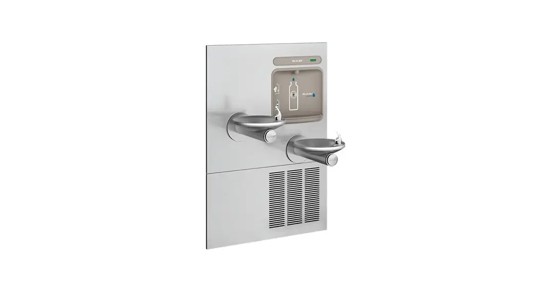
SWIRLFLO® Refrigerated fountains with FLEXI-GUARD® and ezH2O® Bottle Filler
INSTALLATION & USE MANUAL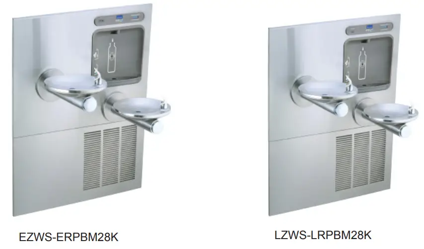
INSTALLER
![]() CAUTION: Review these instructions before beginning installation. Be sure that installation conforms to all plumbing, electrical and other applicable codes.
CAUTION: Review these instructions before beginning installation. Be sure that installation conforms to all plumbing, electrical and other applicable codes.![]() WARNING: When installation is complete, ensure these instructions are left in the plastic bag provided inside the installed unit for future reference.
WARNING: When installation is complete, ensure these instructions are left in the plastic bag provided inside the installed unit for future reference.![]() WARNING: Service to be performed by authorized service personnel only.
WARNING: Service to be performed by authorized service personnel only.
NOTE: It is common practice to ground electrical hardware such as telephones, computers and other devices to available water lines. This can, however, cause electrical feedback in the plumbing circuit, which results in an “electrolysis” effect occurring in the fountain. This may result in water which has a metallic taste to it or has a noticeable increase in the metallic content of the water.
When inspecting plumbing circuit, remember the line may be grounded some distance from the installation, and may occur outside the building or area in which the unit is being installed.
This condition can be avoided (in most cases) by using recommended materials during installation.
Any drain fittings provided by the installer should be made of plastic which will electronically isolate the fountain from the remainder of the building’s plumbing circuits.
Model EZWS-ERPBM28K / LZWS-LRPBM28K
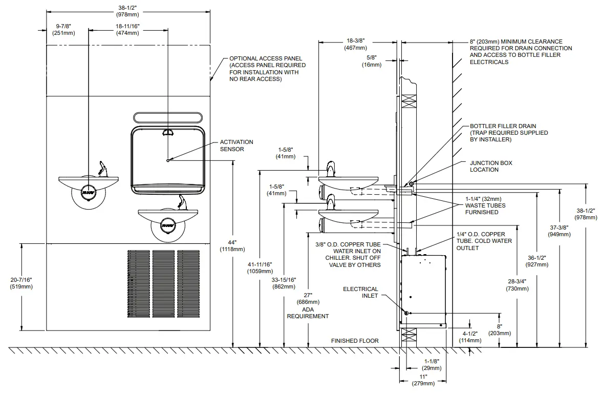 Figure 1 – Rough-in Dimensions
REQUIRED TOOLS AND MATERIALS
These tables show special tools and/or additional materials (not provided) which are necessary to complete installation of these units:
Special Tools
| Item | Description | Quantity |
| NONE |
Additional Materials Not Included
| Item | Description | Quantity |
| 1 | Unplated copper inlet pipe | 1 |
| 2 | Service Stop/Shut-off Valve | 1 |
| 3 | 90° 1-1/4” Drain Line | 1 |
| 4 | 1-1/4” Tee Drain Line | 1 |
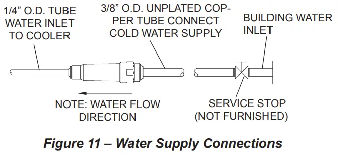
- Make water supply connections. Install a shut-off valve and union connection to building water supply (valve and union not provided). Turn on water supply and flush the line thoroughly.
Caution: DO NOT SOLDER tubes inserted into the strainer or filter head as damage to the o-rings may result. - Install mounting frame (instructions supplied with mounting frame.
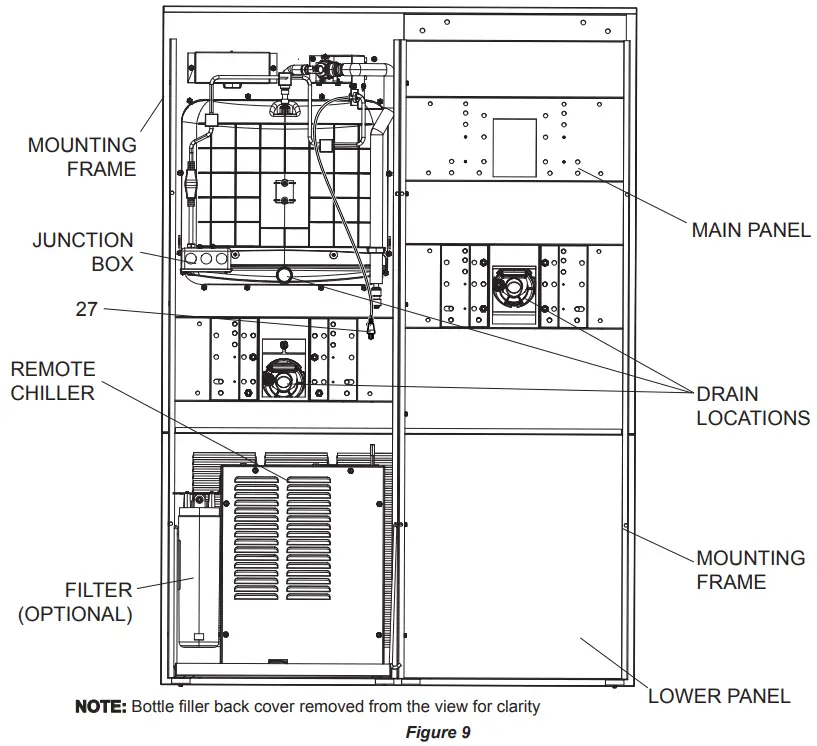
- (For LZWS-LRPBM28K) Install filter bracket on chiller (Fig. 9), then install the filter head to the bracket, plumb from the filter outlet to the chiller inlet with ¼” poly tubing and ¼ x ¼ union, install filter.
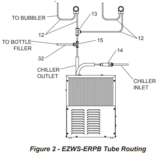
3a. (For EZWS-ERPBM28K) Install strainer on the input tube to the chiller (Fig. 2).
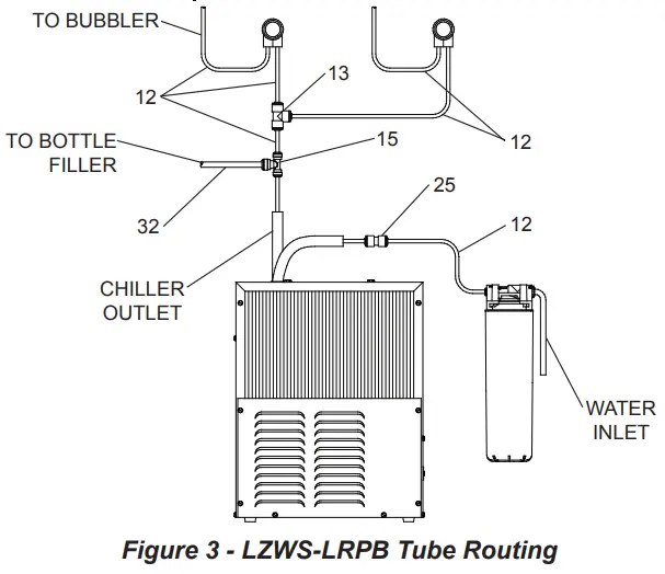
- Install chiller on shelf, install ¼ x ¼ x 3/8 Tee on chiller output tube. Install supplied 4” poly tubing and armaflex to the outlet of the previously installed tee. Connect supplied ¼ x ¼ x ¼ tee to the 4” poly tubing. With the back panel standing close to the frame, connect 3/8” poly tube to the bottle filler.
 Note: Building construction must allow for adequate air flow on both sides, top & back of chiller. A minimum of 4” (102 mm) on both sides & top is required. See chiller installation for additional instructions.
 - Hang main panel on mounting frame hanger. Make sure the power cord, reset switch wire & poly tube do not get pinched between the panel & mounting frame. Ensure the panel en gages at the top. Align fountain holes with mounting frame holes.
- Remove protective coating from main panel.
- Install reset switch for bottle filler (Fig. 4). Snap the switch into position after locating wires through slot. Wrap up the excess cord.

- Install fountains with (8) 5/16-18 HHMS & (8) 5/16-18 nuts (provided) (Fig. 4). Connect the ¼” water lines from each fountain to the remaining openings on the tee at the remote chiller (cut lines to fit as needed).
- Attach waste tubes (1-1/4” O.D.) to 1-1/4” O.D. slip trap. Trap on the bottle filler side must be 1-1/2” O.D. (provided by others).
- Make final water supply connections.
- These products are designed to operate on 20-105 PSI supply line pressure. If inlet pressure is above 105 PSI, a pressure regulator must be installed in the supply line.
(Caution: Any damage caused by connecting these products to a supply line with pressure lower than 20 PSI or higher than 105 PSI IS NOT covered under warranty.) - Make electrical connections to the bottle filler and remote chiller. The LCD Bottle counter should illuminate.
- Verify proper dispensing from the bottle filler by placing a cup, hand or any opaque object in front of sensor area and verify water dispenses. Note: the first initial dispenses might have air in the line which may cause a sputter. This will be eliminated once all air is purged from the line. A steady stream of water assures all air is removed. The sensor has a 20 second maxi mum ON time. It may be necessary to step away from the beam a few times to purge all air. Check for leaks.

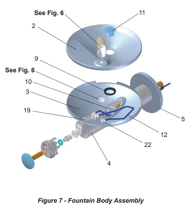
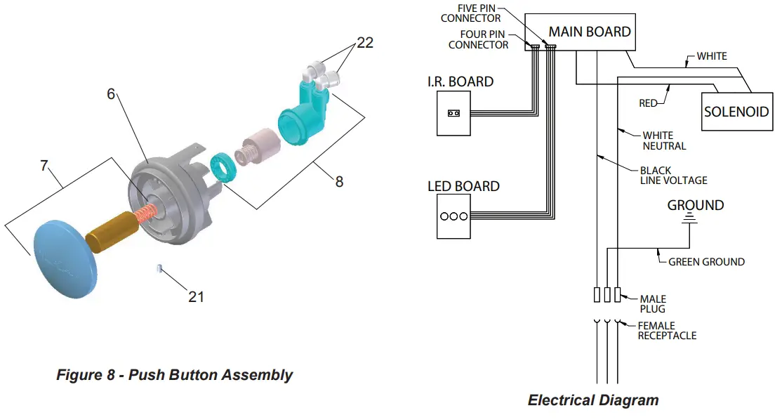
- Check stream height from bubbler. Stream height is factory set for 35 PSI supply. If supply pressure varies greatly from this, remove push button (Item 7 – Fig. 8) and adjust the screw on the regulator (Item 8 – Fig. 8). To remove push but ton, remove setscrew from bottom of sleeve (Item 21). Insert a small punch in screw hole and push up while grasping the push button and pull forward removing the push button. Clock wise adjustment will raise stream height and counterclockwise movement will lower stream height. For best adjustment stream should hit basin approximately 6-1/2” from the bubbler.
Reassemble the push button by pushing in on button until the push button catches in the sleeve. Reinstall the setscrew (Item 21) in the sleeve (Item 6). - Install the cover plates.
- Install the bottom panel, tighten screws (Fig. 4).
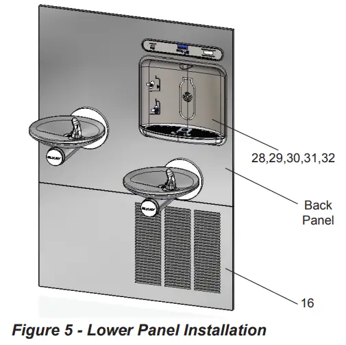
- Optional: Mount optional panels. Slide tongue of panel under edge of already installed panel. Tighten screws.
 Note: Building construction must allow for adequate air flow on both sides, top & back of chiller. A minimum of 4” (102 mm) on both sides & top is required. See chiller installation for additional instructions.
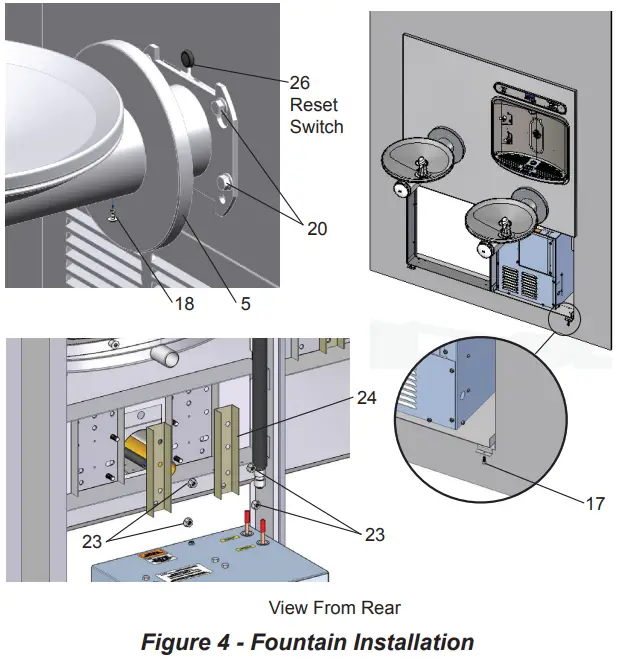
NOTE:
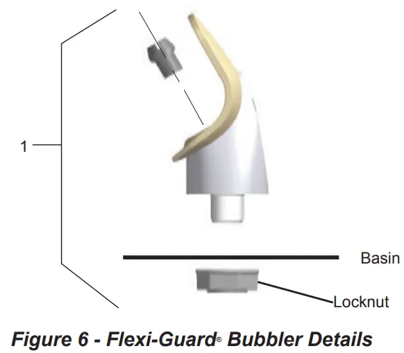
When installing replacement bubbler and pedestal (Fig. 6), tighten locknut only to hold parts snug in position. Do Not overtighten.
BF11 – BF12 PROGRAM SETTING THE CONTROL BOARD
VERIFY CONTROL BOARD SOFTWARE
- To verify the software program of the control board the unit will need to be shut down and restarted. The chiller (if present) does not need to be shut down and restarted.
- Shut down the unit by unplugging the power cord from the wall outlet or switching off the circuit breaker to the unit.
- Restart the unit by plugging the power cord back into the wall outlet or by switching on the circuit breaker to the unit.
- Upon start up, the bottle count display will show the software designation of BF11 or BF12.
ACCESSING THE PROGRAMMING BUTTON
- To access the program button, remove #8-32 screw, pull back cover plate on lower fountain arm (Fig. 4). Reset button is located above fountain arm.
RESET THE FILTER MONITOR
- Instructions apply to filtered units only.
- Depress the program button for approximately 2 seconds until the display changes then release. The display will change and scroll through two messages:
“RST FLTR” – Reset Filter Monitor
“SETTINGS” – System Settings Sub Menu
If the program button is not pushed again the display will scroll through the two messages above for three cycles and then default back to bottle count and be back in run mode. - When the display changes to “RST FLTR”, depress the button again. The display will change to show “FLTR =”. Depress the button again and the display will show “FLTR =0”
- The Green LED should be illuminated indicating that the visual filter monitor has been reset.
SETTING RANGE OF THE IR SENSOR WHERE APPLICABLE
- Depress the program button for approximately 2 seconds until the display changes then release. The display will change and scroll through two messages:
“RST FLTR” – Reset Filter Status LED
“SETTINGS” – System Settings Sub Menu
If the program button is not pushed again the display will scroll through the two messages above for three cycles and then default back to bottle count and be back in run mode. - When the display changes to “SETTINGS”, depress the button again. The display will change to show
“RNG SET” – Range set for IR sensor.
“UNIT TYP” – Type of unit (REFRIG or NON-RFRG)
“FLT SIZE” – Select filter capacity
“RST BCNT” – Reset bottle count - When display shows “RNG SET” push program button once the display will show current value (can be 1 – 10) e.g. “RNG = 3”.
- Once display shows current value push the program button to scroll through value of 1 – 10. Select the desired range setting, “1” being closest to sensor and “10” being farthest away.
- Once range is selected allow approximately 4 seconds to pass and then the display will go back to bottle counter and be in run mode.
- Test bottle filler by placing bottle or hand in front of sensor to make sure water is dispensed.
SETTING UNIT TYPE
- Depress the program button for approximately 2 seconds until the display changes then release. The display will change and scroll through two messages:
“RST FLTR” – Reset Filter Status LED
“SETTINGS” – System Settings Sub Menu
If the program button is not pushed again the display will scroll through the two messages above for three cycles and then default back to bottle count and be back in run mode. - When the display changes to “SETTINGS”, depress the button again.
The display will change to show
“RNG SET” – Range set for IR sensor.
“UNIT TYP” – Type of unit (REFRIG or NON-RFRG)
“FLT SIZE” – Select filter capacity
“RST BCNT” – Reset bottle count
Continued from below: - When display shows “UNIT TYPE” push program button once the display will show current value. Can be REFRIG or NON-RFRG
- Push button once to change value. Once value is selected the display will show the new value. (Can be REFRIG or NON-RFRG)
“REFRIG“ – stands for refrigerated product. In this setting the flow rate is estimated at 1.0 gallon per minute.
“NON-RFRG“ – stands for nonrefrigerated product. In this setting the flow rate is estimated at 1.5 gallons per minute. Both “REFRIG“ and
“NON-RFRG“ simulate 1 bottle equal to 20 oz. - Allow approximately 4 seconds to pass and the display will return to bottle counter and be in run mode.
RESETTING BOTTLE COUNT
- Depress the program button for approximately 2 seconds until the display changes then release. The display will change and scroll through two messages:
“RST FLTR” – Reset Filter Status LED
“SETTINGS” – System Settings Sub Menu
If the program button is not pushed again the display will scroll through the two messages above for three cycles and then default back to bottle count and be back in run mode. - When the display changes to “SETTINGS”, depress the button again.
The display will change to show:
“RNG SET”- Range set for IR sensor.
“UNIT TYP” – Type of unit (REFRIG or NON-RFRG)
“FLT SIZE” – Select filter capacity
“RST BCNT” – Reset bottle count
If the button is not pushed again the display will scroll through the four messages above for three cycles and return to run mode. - When display shows “RST BCNT” push program button once the display will show current value, e.g. “0033183”.
- Once display shows current value push the program button once more to reset back to 0. The display will show BTLCT = 0 for approximately 2 seconds and then return to run mode showing 00000000 bottles.
NOTE: Once the bottle count is reset to zero there is no way to return to the previous bottle count. - Testing the bottle counter:
REFRIG units: Place bottle or hand in front of sensor for approximately 9 seconds to see bottle counter count 00000001, (This is based on filling a 20 oz. bottle).
NON-RFRG units: Place bottle or hand in front of sensor for approximately 6 seconds to see bottle counter count 00000001, (This is based on filling a 20 oz bottle).
SETTING FILTER CAPACITY
- Depress the program button for approximately 2 seconds until the display changes then release. The display will change and scroll through two messages:
“RST FLTR” – Reset Filter Status LED
“SETTINGS” – System Settings Sub Menu
If the program button is not pushed again the display will scroll through the two messages above for three cycles and then default back to bottle count and be back in run mode. - When the display changes to “SETTINGS”, depress the button again.
The display will change to show:
“RNG SET“- Range set for IR sensor.
“UNIT TYP“ – Type of unit (REFRIG or NON-RFRG)
“FLT SIZE” – Select filter capacity
“RST BCNT“ – Reset bottle count
If the button is not pushed again the display will scroll through the four messages above for three cycles and return to run mode. - When display shows “FLT SIZE” push program button once. The display will show current value. Can be 3000GAL or 6000GAL.
- Push program button again to display the desired “FLT SIZE”.
- Allow approximately 4 seconds to pass and the display will return to bottle counter and be in run mode.
ERPBD28WSC LRPBD2_8WSC
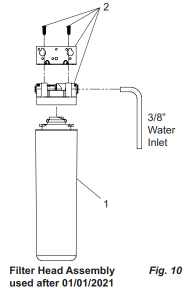
WATERSENTRY® PLUS FILTER PARTS LIST (See Fig. 10)
| ITEM NO. | PART NO. | DESCRIPTION |
| 1 | 51300C | Filter Assy-3000 Gal. |
| 2 | 51469C | Assy-Filter & Brkt includes Fltr Head/Mtg Brkt/John Guest Fittings/Screws |
PARTS LIST
| ITEM NO. | PART NO. | DESCRIPTION |
| 1 | 56073C | Kit – Bubbler Assy |
| 2 | 28708C | Basin – Swirlflow |
| 3 | 28473C | Lower Shell |
| 4 | 45767C | Fountain Body |
| 5 | 28343C | Cover Plate |
| 6 | 45781C | Sleeve |
| 1 | 98871C | Kit – Swirlflo Pushbutton/Spring |
| 2 | 98530C | Kit – Regulator/Spring/Nut |
| 3 | 56163C | Gasket – Drain |
| 4 | 930 | Kit – Drain/Tailpipe |
| 5 | 45768C | Drain – Plug 1-1/2” |
| 6 | 56092C | Poly Tubing (Cut To Length) |
| 7 | 1000001994 | Kit – 70682C 1/4 Tee (3 Pack) |
| 7 | 55996C | Strainer (Provided with Chiller) |
| 8 | 1000002062 | Kit – Tee 1/4 x 1/4 x 3/8 (3 Pack) |
| 9 | 27026C | Lower Panel |
| 10 | 1.11008E+11 | Screw – #10-24 x .62 HHSM |
| 11 | 70432C | Screw – #8-32 x .38 THSM |
| 12 | 38417001 | Screw – #8-18 x .37 HHSM |
| 13 | 75560C | Screw – 5/16-18 x 1.00 HHMS |
| 14 | 75632C | Setscrew – #10-32 x .38 |
| 15 | 1000001772 | Kit – 70817C Elbow 1/4×1/4 (3 Pack |
| 16 | 1.11577E+11 | Nut – Serrated Hex 5/16-18 |
| 17 | 28395C | Bracket – Support |
| 18 | 1000002162 | Kit – 70683C 1/4 Union (3 Pack) |
| 19 | 99003C | Reset Switch Assy |
| 20 | 1000005855 | Power Cord |
BOTTLE FILLER REPLACEMENT PART KITS
| ITEM NO. | PART NO. | DESCRIPTION |
| 28 | 98543C | Kit – Electrical Package |
| 29 | 98544C | Kit – EE Sensor |
| 30 | 2000000503 | Kit – Solenoid Valve Replacement |
| 31 | 98546C | Kit – Aerator Replacement |
| 32 | 98549C | Kit – Hardware & Waterway Parts |
Installation Package
The components for installation are packed in three separate boxes, regardless of the type of unit being installed. The boxes contain the following:
Box No. 1: Wall Frame(s)
Box No. 2: Remote Chiller, ECH8
Box No. 3: Fountain(s), Arm(s) and Panels
Additional materials, as noted in the Parts List, are also shipped in these boxes.
TROUBLESHOOTING & MAINTENANCE
Orifice Assembly: Mineral deposits on orifice can cause water flow to spurt or not regulate. Mineral deposits may be removed from the orifice by poking with a small round file not over 1/8” diameter, or using a small diameter wire.
![]() CAUTION: DO NOT file or cut orifice material
CAUTION: DO NOT file or cut orifice material
Stream Regulator: If orifice is clean, regulate flow as in Step 14 of the installation instructions. If replacement is necessary, see parts list for correct regulator part number.
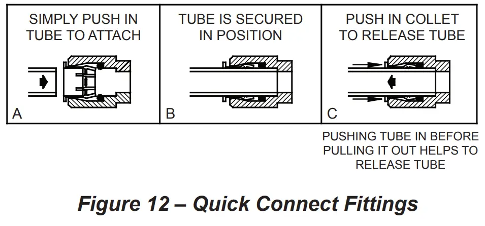
Actuation of Quick Connect Water Fittings: Cooler is provided with lead-free connectors which utilize an o-ring water seal. To remove tubing from the fitting, relieve water pressure, push in on the gray collar while pulling on the tubing. (See Fig. 12) To insert tubing, push tube straight into fitting until it reaches a positive stop (approximately 3/4”).
OPERATION OF QUICK CONNECT FITTINGS
FOR PARTS, CONTACT YOUR LOCAL DISTRIBUTOR OR CALL 1.800.834.4816
REPAIR SERVICE INFORMATION TOLL FREE NUMBER 1.800.260.6640
ELKAY MANUFACTURING COMPANY • 1333 BUTTERFIELD ROAD SUITE 200 DOWNERS GROVE, IL 60515 • 630.574.8484
• www.elkay.com
2000000491 (Rev. A – 01/22)


