FUJITSU WPYA050LE Air to Water Heat Pump User Manual
SPECIFICATION
| Unit | WPYA050LE | ||||
| Cooling Capacity | kW | 4.0 | |||
| Heating Capacity | kW | 5.0 | |||
| Power source | phase | Single | |||
| V | 230 | ||||
| Hz | 50 | ||||
Airflow Method | OUTLET INTAKE | TOP VIEW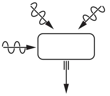 | |||
Electrical Data | Input | W | Cooling Heating | ;; | 10251460 |
| Running Current (MAX.) | A | Cooling Heating | ;; | 4.5(6.6)6.4(10.9) | |
| Water Pipe Size | Out Return | ;; | R3/4(20A) R3/4(20A) | ||
| Power Cord | Number of core-wire | core-wire / 1.5~2.0mm2 | |||
| Dimensions | Height | mm | 675 | ||
| Width | mm | 825 | |||
| Depth | mm | 300 | |||
| Net Weight | kg | 50 | |||
| Air Circulation | Type | Propeller Fan | |||
| Motor Type | DC brushless(8-pole) | ||||
| Rated Output | W | 30 | |||
| Heat Exchanger | Plate fin configuration,forced draft16.9 FPI | ||||
| Refrigerant Control Device | Expansion Valve | ||||
| Refrigerant (R410A ) | g | 1050 | |||
| Thermostat | Electronic Control | ||||
UNIT
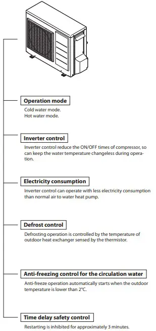
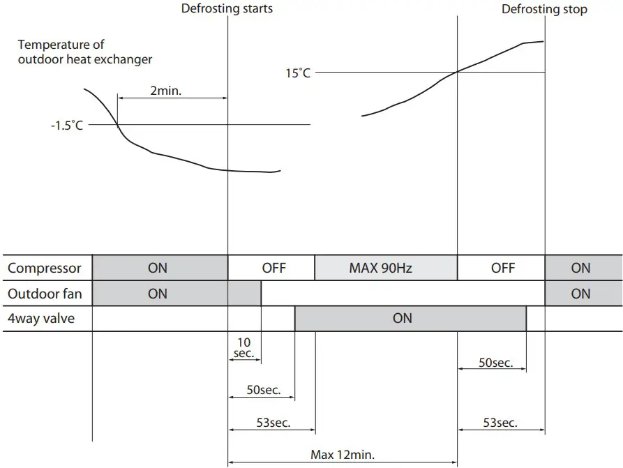
DEFROSTING OPERATION(FOR A UNIT HEAT EXCHANGER)
- Defrosting operation is controlled by the temperature of outdoor heat exchanger sensed by the thermistor and the timer switch.
- Defrosting operation starts when the both of the following conditions are met at the same time. a)40 minutes’(*1) of continuous run of the compressor after the start of heating operation or after the completion of previous defrosting operation. b)The temperature of the outdoor heat exchanger stays lower than -1.5°C(*2) continuously for two minutes.
- Defrosting operating is called off if either of the following conditions is met. a)The temperature of outdoor heat exchanger rises to 15°C while 4-way-valve is ON. b)12 minutes has passed since compressor turned ON.
- Working condition of frost protection heater for expansion vessel The heater turns ON if the outdoor temperature keeps below 3 degree for 1 minute. The heater turns OFF if the outdoor temperature keeps above 5 degree for 1 minute.
(*1) The period of time may be different in different cases.
(*2) This temperature may be different in different cases.
- Working condition of frost protection heater for expansion vessel
The heater turns ON if the outdoor temperature keeps below 3 degree for 1 minute.
The heater turns OFF if the outdoor temperature keeps above 5 degree for 1 minute.
FOR YOUR SAFETY USE
- For the safety and proper use and handling of the product, please read and follow the instructions carefully.
- The meaning of the marks below are as follows.
Warning Improper use may cause the risk of death or serious injury of the user.
 Caution
 Strict enforcement
 High Voltage
- Connect the earthing cable
 Prohibited
 Strict enforcement
 Prohibited
| Danger | |
| Check Point |
|
| |
Use designated parts or accessories to avoid accidents. | |
| |
| |
| |
| Check Point |
|
| |
ERROR CODES
The error codes displayed on the unit display board the location of the breakdown or abnormality.
| UNIT | APPEARANCE, PORTION, PARTS SEEMED WRONG | METHOD OF CHECK | TROUBLESHOOTING | |
| ERROR CODES | ||||
| − | do not work at all | POWER SUPPLY | check the power supply. | confirm the power supply. |
| FUSE CF1 | check the electric continuity by tester. [see fig.1] | PCB(CONTROLLER) should be replaced. | ||
| FUSE CF3 | check the electric continuity by tester. [see fig.1] | PCB(CONTROLLER) should be replaced. | ||
| PCB(CONTROLLER) | other than described above. | PCB(CONTROLLER) should be replaced. | ||
| A0 | DC voltage Error | FAN MOTOR | operate without lead wire for FAN MOTOR. | if the same error code appears again, PCB (CONTROLLER) or PUMP should be replaced.if other error codes appear, FAN MOTOR should be replaced. |
| PUMP | operate without lead wire for PUMP. | if the same error code appears again, PCB (CONTROLLER) or FAN MOTOR should be replaced.if other error codes appear, PUMP should be replaced. | ||
| REACTOR | check lead wires are connected to the connector of REACTOR properly. | if the lead wires are not connected, connect them to the con- nector properly. | ||
| check the electric continuity between connector of REACTOR by tester. | if there is no electric continuity for REACTOR, it should be re- placed. | |||
| POWER SUPPLY | check the power supply. | confirm the power supply. | ||
| A1 | Discharge temperature Error | SENSOR, TEMP. DISCHARGE | check the resistance by tester. [see table 4] | SENSOR, TEMP. DEFROST should be replaced. |
| GAS LEAKAGE | check the service valve and refrigerant circuit (pipe). | collect refrigerant once, then recharge with prescribed mass. | ||
| A2 | protective action against excesscurrent DC current detection | UNREASONABLE OPERATION UNDER OVERLOAD | check the place of installation (blockage of air inlet & outlet ).check the excess gas. | ensure the installation position to avoid blockage of air inlet & outlet. |
| if excess gas is observed, collect all refrigerant once, then re- charge with prescribed mass. | ||||
| DROP OF POWER VOLTAGE | check the power voltage (230V) during operation. | confirm the power supply voltage. (230V) | ||
| MOMENTARY STOP OF POWER(IN CASE OF LIGHTNING) | restart operation. | |||
| PCB(CONTROLLER) | operate without the junction connector of compressor lead wire. | if the same error code appears again, PCB(CONTROLLER) should be replaced. | ||
| COMPRESSOR | other than described above. | COMPRESSOR should be replaced. | ||
| A4 | protective action against excesscurrent AC current detection | UNREASONABLE OPERATION UNDER OVERLOAD | check the place of installation (blockage of air inlet & outlet ).check the excess gas. | ensure the installation position to avoid blockage of air inlet & outlet. |
| if excess gas is observed, collect all refrigerant once, then re- charge with prescribed mass. | ||||
| DROP OF POWER VOLTAGE | check the power voltage (230V) during operation. | confirm the power supply voltage. (230V) | ||
| MOMENTARY STOP OF POWER (IN CASE OF LIGHTNING) | restart operation. | |||
| A5 | abnormal revolution of com- pressor | UNREASONABLE OPERATION UNDER OVERLOAD | check the place of installation (blockage of air inlet & outlet).check the excess gas. | ensure the installation position to avoid blockage of air inlet & outlet. |
| if excess gas is observed, collect all refrigerant once, then re- charge with prescribed mass. | ||||
| CLOGGED THE CIRCULATION PUMP AND/ OR HEATING CIRCUIT | check the pump and heating circuit. | remove the clog, then restart operation. | ||
| DROP OF POWER VOLTAGE | check the power voltage (230V) during operation. | confirm the power supply voltage. (230V) | ||
| MOMENTARY STOP OF POWER (IN CASE OF LIGHTNING) | restart operation. | |||
| COMPRESSOR or PCB (CONTROLLER) | other than described above. | COMPRESSOR should be replaced. | ||
| A6 | Suction temp. sensor Error | SENSOR, TEMP. SUCTION | check the resistance by tester. [see table 2] | if the sensor is faulty, it should be replaced. |
| A7 | Defrost temp. sensor Error | SENSOR, TEMP. DEFROST | check the resistance by tester. [see table 2] | if the sensor is faulty, it should be replaced. |
| A8 | Discharge temp. sensor Error | SENSOR, TEMP. DISCHARGE | check the resistance by tester. [see table 4] (*1) | if the sensor is faulty, it should be replaced. |
ERROR CODES
| UNIT | APPEARANCE, PORTION, PARTS SEEMED WRONG | METHOD OF CHECK | TROUBLESHOOTING | |
| ERROR CODES | ||||
| C0 | PCB (CONTROLLER) Error | PCB (CONTROLLER) | PCB(CONTROLLER) should be replaced. | |
| C2 | Outdoor temp. sensor Error | SENSOR, TEMP. OUTDOOR | check the resistance by tester. [see table 1] | if the sensor is faulty, it should be replaced. |
| C3 | Fan motor Error | FAN MOTOR | check the voltage of FAN MOTOR. [see fig. 2] | check the voltage of FAN MOTOR. [see fig. 2]if the voltage is normal, FAN MOTOR should be replaced.if the voltage is faulty, PCB(CONTROLLER) should be replaced. |
| PCB (CONTROLLER) | ||||
| C4 | rise of temperature of PCB (CONTROLLER) | MIS-INSTALLATION | check the place of installation (blockage of air inlet & outlet). | ensure the installation position to avoid blockage of air inlet & outlet. |
| SENSOR, TEMP. PCB (CONTROLLER) | PCB(CONTROLLER) should be replaced. | |||
| C5 | PCB (CONTROLLER) sensorError | SENSOR, TEMP. PCB (CONTROLLER) | PCB(CONTROLLER) should be replaced. | |
| C6 | PCB (CONTROLLER) Error | PCB (CONTROLLER) | PCB(CONTROLLER) should be replaced. | |
C7 | I/F PCB serial error | MIS-WIRING [ PCB (CONTROLLER ) – I/ F PCB CONNECTING CABLE ] OR RARE CONTACT | check the wiring connection and rare contact. | after correcting mis wiring, restart operation. |
| I/F PCB | other than described above. | I/F PCB should be replaced. | ||
| PCB (CONTROLLER) | other than described above. | PCB(CONTROLLER) should be replaced. | ||
| C8 | PCB (CONTROLLER) error | PCB(CONTROLLER) | PCB(CONTROLLER) should be replaced. | |
| CC | Heat pump regulator PCB se- rial error | MIS-WIRING (I/F PCB-HEAT PUMP REGU- LATOR) OR RARE CONTACT | check the wiring connection and rare contact. | after correcting mis wiring, restart operation. |
| I/F PCB | other than described above. | I/F PCB should be replaced. | ||
| Heat pump regulator | other than described above. | PCB(CONTROLLER) should be replaced. | ||
| E4 | Outgoing circulating temp. sensor Error | SENSOR, TEMP. OUTGOING CIRCULATING WATER | check the resistance by tester. [see table 3] | if the sensor is faulty, it should be replaced. |
| E5 | Return circulating water temp. sensor Error | SENSOR, TEMP. RETURN CIRCULATING WATER | check the resistance by tester. [see table 3] | if the sensor is faulty, it should be replaced. |
| P1 | Pump Error | PUMP or PCB (CONTROLLER) | check the voltage of PUMP. [see fig. 3] | if the voltage is normal, PUMP should be replaced.if the voltage is abnormal, PCB(CONTROLLER) should be re- placed. |
| CLOGGED THE CIRCULATION PUMP AND/ OR HEATING CIECUIT | check the pump and heating circuit. | remove the clog, then restart operation. | ||
| PCB (DISPLAY) cannot be operated PCB (DISPLAY) does not display any- thing | Lead wire of PCB(DISPLAY) | check lead wires are connected to the connectors prop- erly. | connect the connectors to both PCB (DISPLAY) and PCB (CON- TROLLER) steadily. | |
| ensure that there is no disconnection for the lead wires. | lead wires should be replaced. | |||
| PCB(DISPLAY) | other than described above. | PCB(DISPLAY) should be replaced. | ||
| PCB(CONTROLLER) | PCB(CONTROLLER) should be replaced. | |||
| not cool down not warm up | 4-WAY VALVE | check the resistance by tester. [see fig. 4] | if the value is abnormal, the coil should be replaced. | |
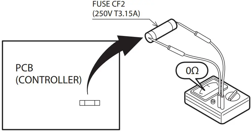
| energization during cooling operation is 230V.if there is no energization, check the electric continuity of FUSE CF2. [see fig.1] | if there is no electric continuity for FUSE CF2, it should be re- placed.if there is electric continuity for FUSE CF2, PCB(CONTROLLER) should be replaced. | |||
| SHORT CYCLE (INSUFFICIENT AIR CIRCU- LATION) | check the blockage of air inlet & outlet. | ensure the installation position to avoid blockage of air inlet & outlet. | ||
| SENSOR,TEMP. OUTGOING AND RETURN CIRCULATING WATER | check the resistance by tester. [see table 3] | if any of these sensors is faulty, it should be replaced. | ||
| GAS LEAKAGE | check the service valve and refrigerant circuit (pipe). | after fixing the leakage point, collect the refrigerant once, then recharge with prescribed mass. | ||
| CLOGGED HEATING CIRCUIT | check temperature difference heating flow/return. [see page 15]large difference means flow rate is too low. | remove the clog, then restart operation. | ||
ELECTRIC CHARACTER
[table 1] Sensor, temp. outdoor| Temp.(°C) | Resistance(kΩ) |
| 0 | 31 |
| 5 | 24 |
| 10 | 19 |
| 15 | 15 |
| 20 | 12 |
| 25 | 10 |
| 30 | 8.2 |
| 35 | 6.7 |
| 40 | 5.5 |
| 45 | 4.6 |
| 50 | 3.8 |
| 55 | 3.2 |
| Temp.(°C) | Resistance(kΩ) |
| 0 | 29 |
| 5 | 23 |
| 10 | 19 |
| 15 | 15 |
| 20 | 12 |
| 25 | 10 |
| 30 | 8.3 |
| 35 | 6.9 |
| 40 | 5.7 |
| 45 | 4.8 |
| 50 | 4.1 |
| 55 | 3.4 |
| Temp.(°C) | Resistance(kΩ) |
| 0 | 25 |
| 10 | 16 |
| 20 | 10 |
| 30 | 7.0 |
| 40 | 4.9 |
| 50 | 3.5 |
| 60 | 2.5 |
| Temp.(°C) | Resistance(kΩ) |
| 10 | 100 |
| 20 | 64 |
| 35 | 33 |
| 40 | 27 |
| 50 | 18 |
| 80 | 6.4 |
DISPLAY OF ERRORS IN THE PAST
- Display method
- For a unit display board
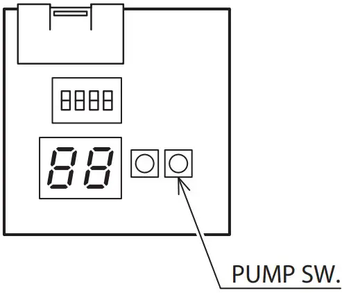
Press and hold the PUMP SW. and RESET SW. at the same time for 5 seconds to display a past error code and its sequence number. The PUMP SW. can then be used to select between a maximum of 8 past error codes to display. (If there are no error codes, “ – – ” is displayed.)
- For a unit display board
- Display cancellation
- For a unit display board
While an error code is being displayed, press and hold the PUMP SW. and RESET SW. at the same time for 5 seconds to cancel the error code display and turn off the display. Alternatively, if no operations are performed for 5 minutes, the error code display is automatically cancelled and the display turned off. While an error code is being displayed, press and hold the reset switch for 10 seconds or more to delete all past error codes. The display turns to “ – – ”.
- For a unit display board
CHECK FOLLOWING STEPS
[fig. 1] Continuity of current fuse on the PCB (CONTROL-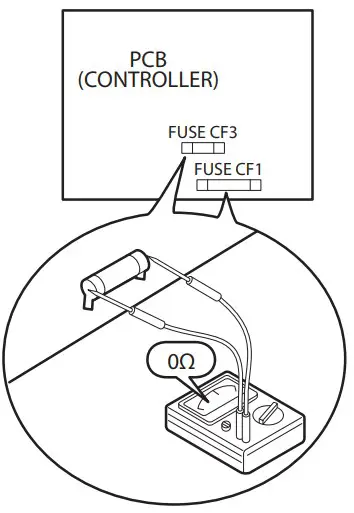
– [fig. 2] Voltage of FAN MOTOR on the PCB(CONTROLLER)
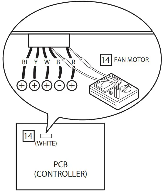
Measure voltage between the connector pins of connector 14 . Connector 14 shall be checked during heating or cooling operation.
Measure voltage as follows without taking off the connector 14 .
Measure voltage between the connector pins of connector 13 . Connector 13 shall be checked during heating or cooling operation. Measure voltage as follows without taking off the connector 13 . PCB (CONTROLLER) is Normal PCB (CONTROLLER) is Normal between red + and black − approx. DC200~370V between yellow + and black − approx. DC3~7V between white + and black − approx. DC15V between white + and black − approx. DC200~370V between brown + and black − approx. DC3~7V between red + and black − approx. DC15V FAN MOTER Error
[fig. 3] Voltage of PUMP on the PCB(CONTROLLER)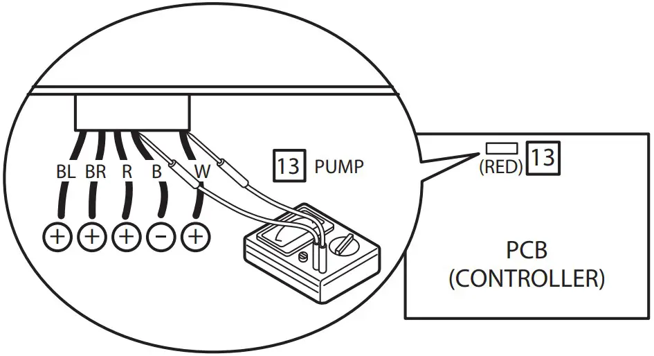
Measure voltage between the connector pins of connector 13 . Connector 13 shall be checked during heating or cooling operation. Measure voltage as follows without taking off the con nector 13 .
- between white + and black − approx. DC200~370V
- between brown + and black − approx. DC3~7V
- between red + and black − approx. DC15V
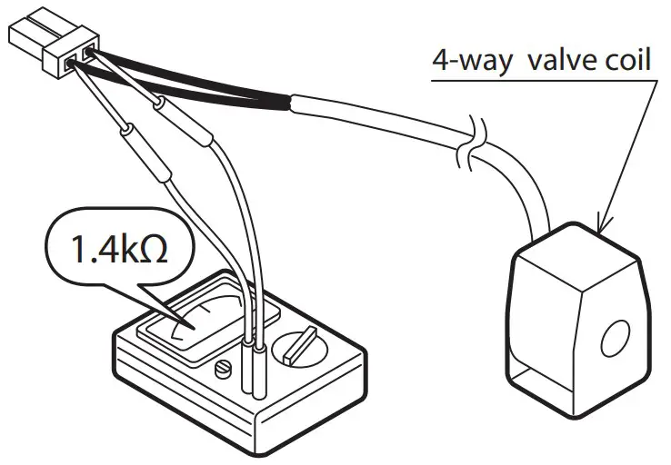
Take off the connector and check the resistance 4-way valve coi
[fig. 5] Resistance of the heater for tank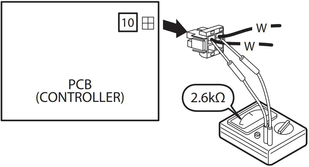
HOW TO DETACH PCB(CONTROLLER)
![]() Wait at least 5min. After turning off the power before servicing.
Wait at least 5min. After turning off the power before servicing.
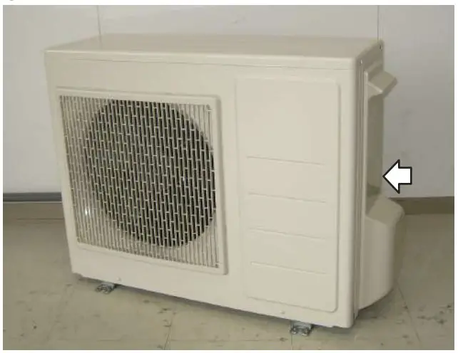
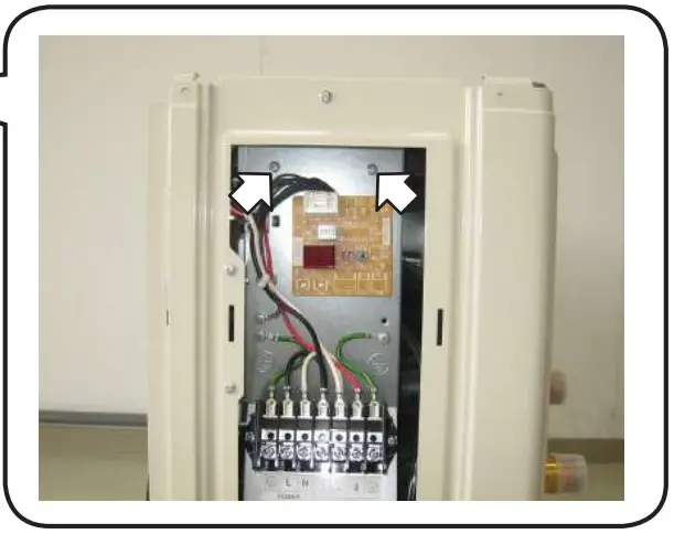
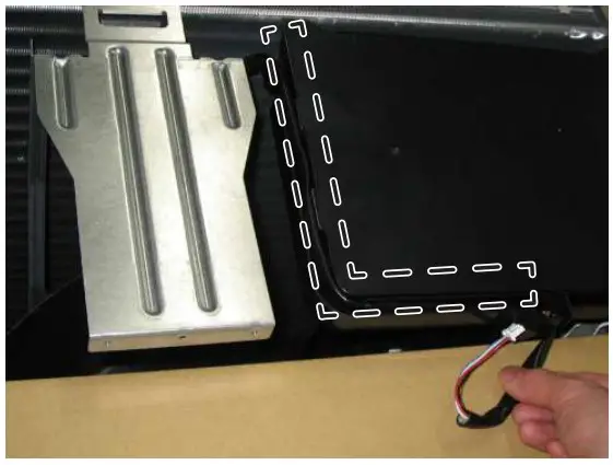
- Unscrew and detach WIRING LID. [See picture 1]

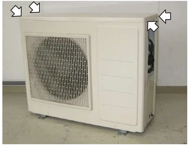
- Unscrew (4pcs) and detach TOP PANEL. [See pictuere 2]
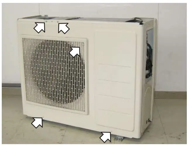
- Unscrew (5pcs) and detach FRONT PANEL ASSY. [See picture 3]
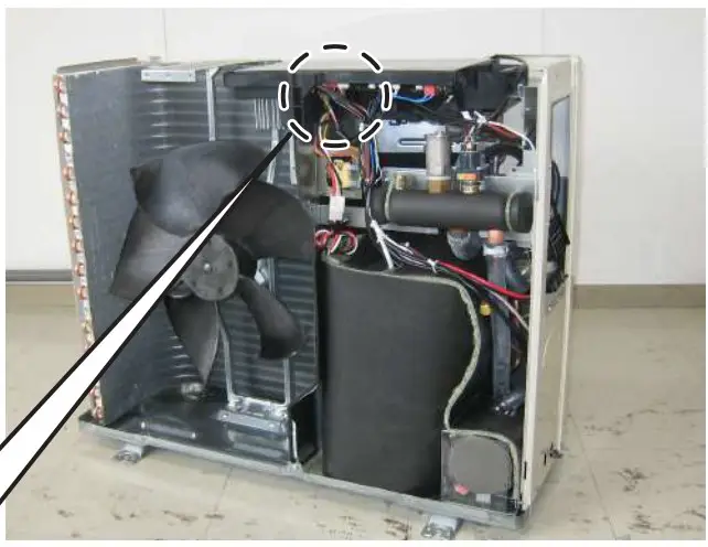
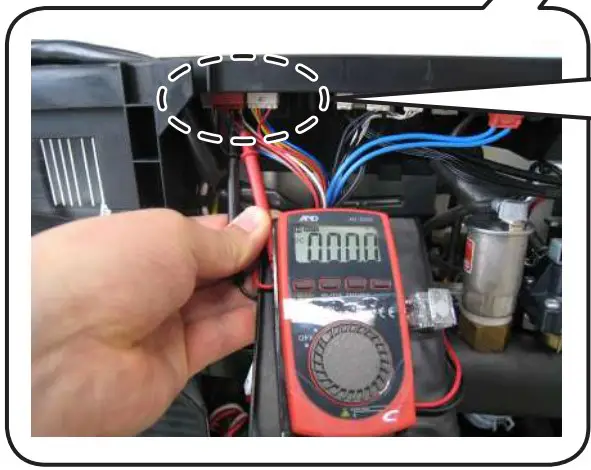
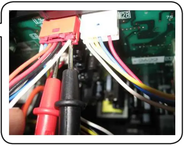
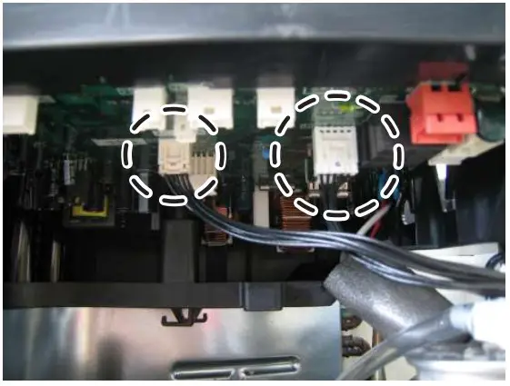
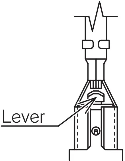
- Be sure to confirm the voltage between the connector pins of pump connector 13 (between white + and black _ ) is less than DC 10V with tester before disconnect lead wires. [See picture 4-1, 4-2, 4-3]

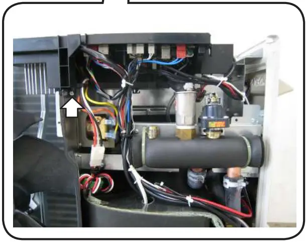
- Unscrew (3pcs). [See picture 5-1,5-2,5-3]


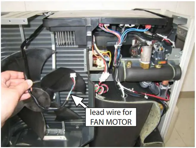
- Disconnect lead wire for FAN MOTOR from CASE OF PCB. [See picture 6]

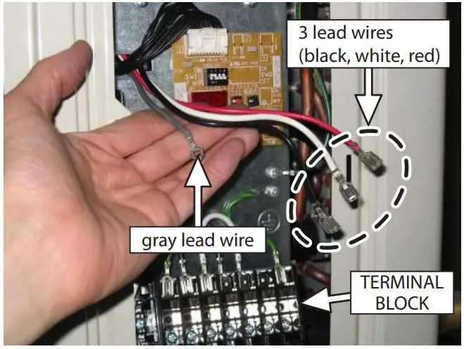
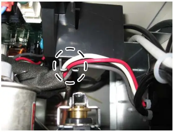
- Disconnect 3 lead wires (black, white, red) from TERMINAL BLOCK. Unscrew the gray lead wire. [See picture 7]
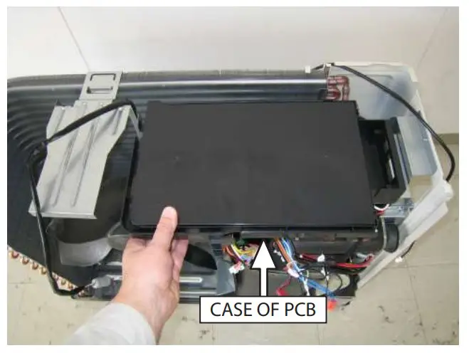
- Disconnect all lead wires from PCB(CONTROLLER) and move CASE OF PCB forward. [See picture 8]
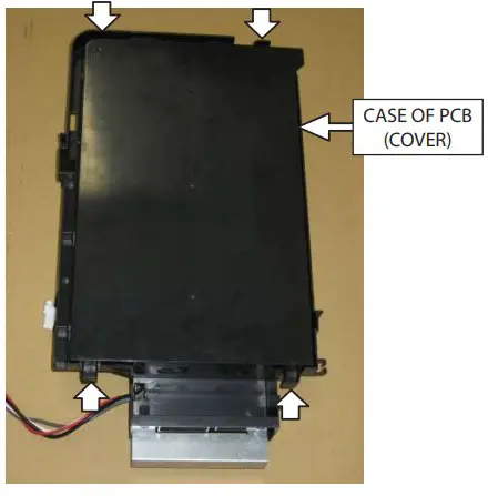
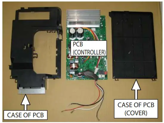
- Unlock 4 hooks and detach CASE OF PCB(COVER). [See picture 9]

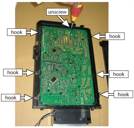
- Unscrew and unlock 6 hooks. [See picture 10] Unscrew and unlock hooks one by one and detach PCB (CONTROLLER) slowly.

- Detach PCB (CONTROLLER) from CASE. [See picture 11]

- Take the reverse procedure of “HOW TO DETACH PCB(CONTROLLER)”.
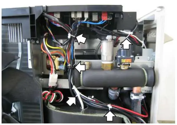
- Be sure to confirm 3 lead wires (black, white, red) and the gray lead wire are hooked. [See picture 12-1]

- Ensure that PCB (DISPLAY) is connected to PCB (CONTROLLER) properly. [See picture 12-2]
- Be sure to put FAN MOTOR lead wires in the passage along the side of CASE OF PCB. [See picture 12-3]
- Bind lead wires as they were. [See picture 12-4]

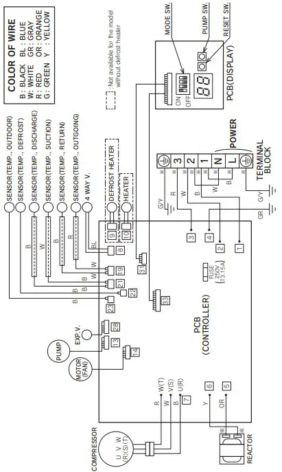
WIRING DIAGRAM
![]() WARNING !
WARNING !
![]() Electric Shock !
Electric Shock !
- Don’t touch electrically charged parts, as electric shock may occur even if they are switched off.
- Be sure to wait at least 5 min. after turning off the powerand to confirm the voltage between the connector pins of pump connector 13 [between white and black ] is less than DC10V with a tester before servicing.
- Do not touch any part of the electric circuit (including the wiring of thermistor and others), as it has high voltage against the ground.
- Pay attention not to damage the insulated wire when you tighten the screw, as the exposed wire may cause electric shock or malfunction.
- Do not ground the oscilloscope when you operate. You might destroy it. Also do not touch any metal part of the oscilloscope while operating.
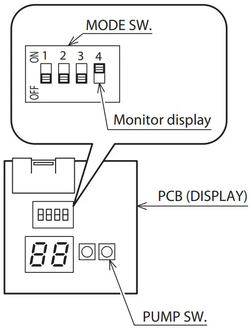
MONITOR DISPLAY METHOD
- Switch “ ON ” the MODE SW. 4 on the unit PCB (DISPLAY). The monitor number and monitor data are alternately displayed.
- Push the PUMP SW. of the unit PCB (DISPLAY). Every time the PUMP SW. is pressed the display changes in the sequence below.
- Switch “ OFF ” the MODE SW. 4 after completing the check.

| Monitor | Monitor data display contents | |
| d0 | Circulating water return temperature | Units of 1°C |
| d1 | Compressor operating frequency | Units of 1Hz |
| d2 | Discharge temperature | Units of 1°C |
| d3 | Power consumption value | Units of 100W |
| d4 | ||
| d5 | Defrost thermistor temperature | Units of 1°C |
| d6 | Ambient air temperature | Units of 1°C |
| d7 | ||
| d8 | Suction temperature | Units of 1°C |
| d9 | Circulating water outgoing temperature | Units of 1°C |
CHARGE THE CIRCULATION WATER AND AIR PURGE IN WATER CIRCUIT
- When you push PUMP SW on display PCB, the water pump is started to operate to circulate the water. The each digital segment of right side on display PCB lights in sequence during operating the pump.
- The pump is automatically stopped after operating for 10 minutes. If it is not enough to let the air out of water circuit, please push PUMP SW once again after the pump stopped. When you would like to stop operating the pump before the pump is automatically stopped, please push PUMP SW once again.

FREEZE PREVENTION SETTING
If the outside temperature falls below about 2°C, freeze prevention operation is possible depending on the unit MODE SW. 1
ON : Freeze prevention operation (When the outdoor temperature falls below about 2°C , the circulating water is warmed and circulated.)
The factory setting is “ ON : 2. Freeze prevention operation ”.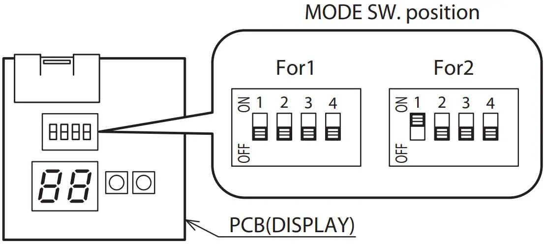
| No. | PARTS NAME | PARTS No. |
| 1 | OUTLET GRILLE | 20567790 |
| 2 | FRONT PANEL ASSY. | 20691630 |
| 3 | RIGHT SIDE PANEL | 20691780 |
| 4 | LEFT SIDE PANEL ASSY. | 20691800 |
| 5 | TOP PANEL ASSY. | 20699381 |
| 6 | PROPELLER FAN | 52630340 |
| 7 | MOTOR | 30137960 |
| 8 | BRACKET,MOTOR | 20681780 |
| 9 | SENSOR (TEMP. OUTDOOR) | 30138450 |
| 11 | BOTTOM PANEL ASSY. | 20705043 |
| 12 | WIRING LID ASSY. | 20698380 |
| 13 | CONDENSER ASSY. | 20692130 |
| 14 | COIL,EXPANSION VALVE | 30137500 |
| 15 | EXPANSION VALVE | 51914522 |
| 16 | SENSOR (TEMP. DEFROST) | 30135060 |
| 17 | HEAT EXCHANGER ASSY. | 20692900 |
| 18 | PUMP ASSY. | 20692782 |
| 20 | COMPRESSOR | 30137520 |
| 21 | VIBRATION PROOF RUBBER | 30137560 |
| 22 | SENSOR (TEMP. DISCHARGE & SUCTION) | 30135050 |
| 23 | ||
| 24 | SENSOR (TEMP. CIRCULATING WATER) | 30137510 |
| 25 | REACTOR | 30098720 |
| 26 | TERMINAL BLOCK | 30112970 |
| 27 | PCB (DISPLAY) | 30137930 |
| 28 | PCB (CONTROLLER) | 30154050 |
| 29 | RUBBER HOSE (FOR RELIEF VALVE) | 30137730 |
| 30 | RUBBER HOSE (FOR AIR PURGE VALVE) | 30137740 |
| 31 | HOSE BAND (FOR RELIEF VALVE) | 30084480 |
| 32 | HOSE BAND (FOR AIR PURGE VALVE) | 68616090 |
| 33 | SOUND PROOF MATERIAL 1 | 20694790 |
| 34 | SOUND PROOF MATERIAL 2 | 20694800 |
| 35 | SOUND PROOF MATERIAL 3 | 20694810 |
| 36 | SOUND PROOF MATERIAL 4 | 20694820 |
| 37 | SOUND PROOF MATERIAL 5 | 20695360 |
| 38 | OUTDOOR THERMISTOR HOLDER | 20696760 |
| 39 | COIL, 4-WAY VALVE | 30137490 |
| 41 | RELIEF VALVE | 30112670 |
| 42 | AIR PURGE VALVE | 30112680 |
| 43 | PLUG | 20742470 |
| 44 | 4-WAY VALVE | 30104090 |
| 45 | CIRCULATING WATER OUTGOING PORT ASSY. | 20694710 |
| 46 | CIRCULATING WATER RETURN PORT ASSY. | 20694740 |
| 47 | RUBBER HOSE 1 | 20692840 |
| 48 | RUBBER HOSE 2 | 20692850 |
| 49 | RUBBER HOSE 3 | 20692860 |
| 50 | RUBBER HOSE 4 | 20692870 |
| 51 | RUBBER HOSE 5 | 20726660 |
| 53 | O RING (P3) | 30015770 |
| 54 | O RING (P4) | 01107120 |
| 55 | O RING (P6) | 01107600 |
| 56 | O RING (P14) | 01107150 |
| 57 | QUICK FASTENER | 30089210 |
| 58 | QUICK FASTENER | 00633600 |
| 59 | QUICK FASTENER | 00601690 |
| 60 | HOSE BAND | 30138460 |
| 61 | HOSE BAND | 30072400 |
| 62 | HOSE BAND | 30122230 |
| 65 | DRAIN PLUG | 10056760 |
| 66 | CONNECTOR PIPE ASSY. | 20768430 |
| 67 | CASE OF PCB | 20682670 |
| 68 | CASE OF PCB (COVER) | 20696130 |
UTZ-AT10CA
| No. | PARTS NAME | PARTS No. |
| 1 | Interface Kit | 20612052 |