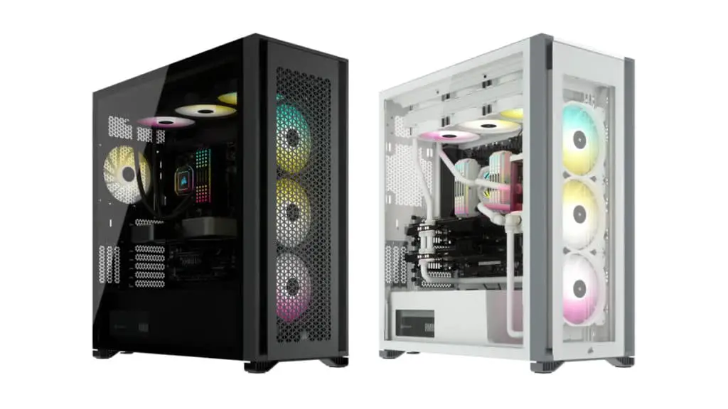
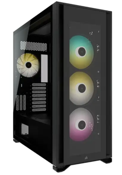
CORSAIR iCUE 7000X RGB Full-Tower PC Case
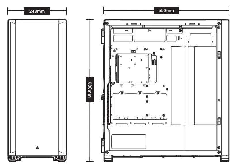
CASE SPECIFICATIONS
Length…………………………………………………………………………………………………………………………………………..550mm
Width…………………………………………………………………………………………………………………………………………….248mm
Height……………………………………………………………………………………………………………………………………………600mm
Maximum GPU length……………………………………………………………………………………………………………………..330mm
Maximum CPU height……………………………………………………………………………………………………………………..175mm
Maximum PSU length……………………………………………………………………………………………………………………..225mm
Fan locations:
Front………………………………………………………………………………………..4x 120mm / 3x 140mm (3x 140mm Included)
Top………………………………………………………………………………………………………………………….3x 120mm / 3x 140mm
Rear………………………………………………………………………………………………….120mm / 140mm (1x 140mm Included)
Motherboard tray………………………………………………………………………. 4x 120mm (Requires removal of cable cover)
Radiator compatibility:
Front………………………………………………………………………………………………………………………………. 480mm / 420mm
Top…………………………………………………………………………………………………………………………………. 420mm / 360mm
Rear……………………………………………………………………………………………………………………………….. 140mm / 120mm
Motherboard tray……………………………………………………………………………………………………………… 480mm / 420mm
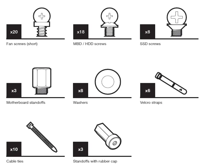
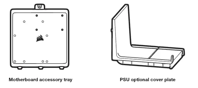
ACCESSORY KIT CONTENTS
CASE FEATURES
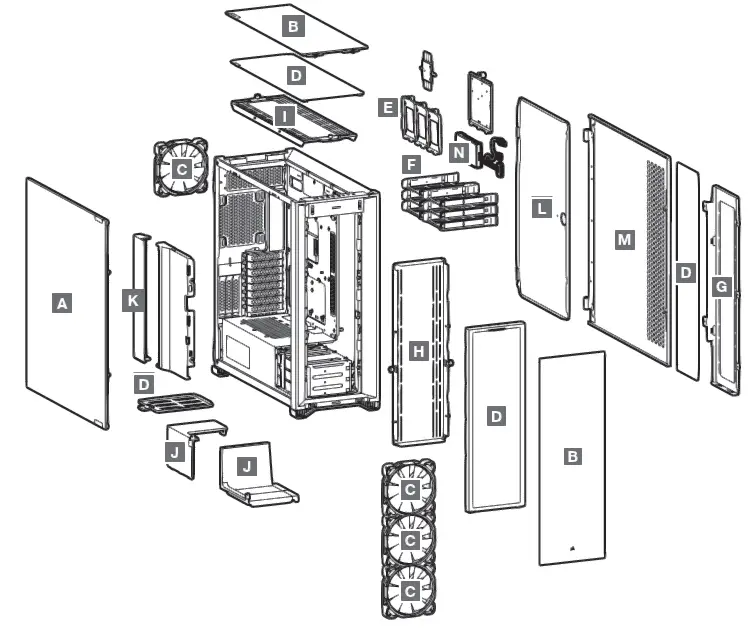
- A — TEMPERED GLASS SIDE PANEL
- B — TEMPERED GLASS FRONT AND TOP PANELS
- C — 4x SP RGB ELITE 140MM FANS
- D — 4x DUST FILTERS
- E — 3x SSD TRAYS
- F — 6x HDD TRAYS
- G — MOTHERBOARD TRAY FAN BRACKET
- H — FRONT FAN BRACKET
- I — TOP FAN BRACKET
- J — PSU SHROUD COVER (ALTERNATE)
- K — CABLE COVER
- L — MOTHERBOARD STEEL HINGED DOOR
- M — SOLID SIDE PANEL
- N — COMMANDER CORE XT
How to Assembly
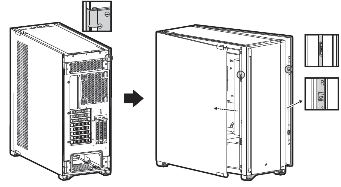
HINGED SIDE PANELS
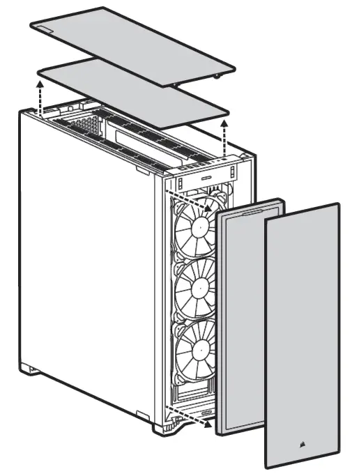
REMOVING THE FRONT AND TOP BEZEL
REMOVING THE CABLE BAR
Step 1: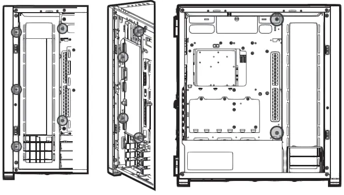
Step 2:
Step 3:
Step 4:
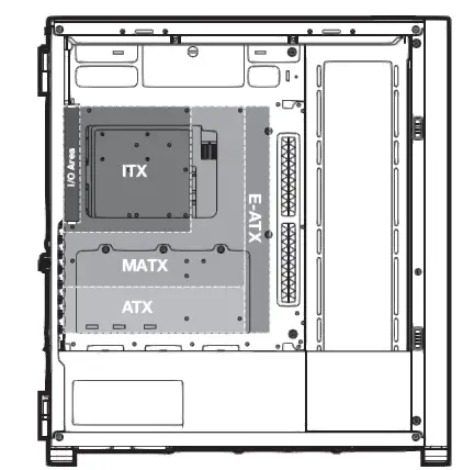
INSTALLING THE MOTHERBOARD
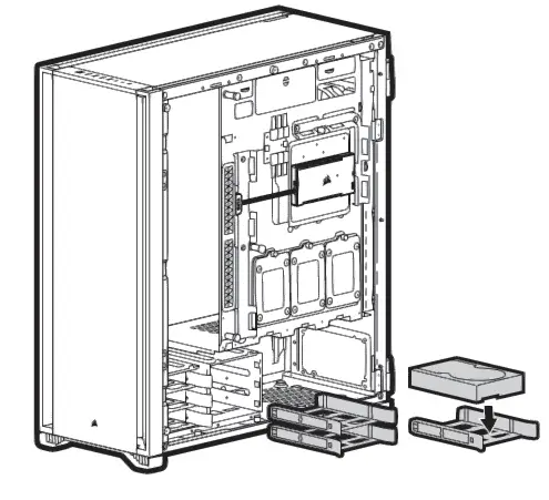
INSTALLING HDDS
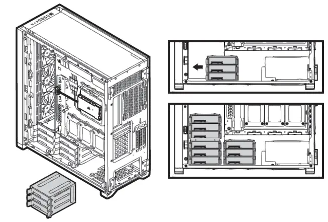
MOVING THE HDD CAGE
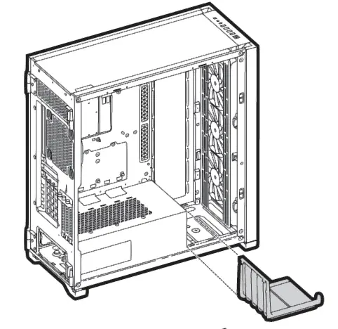
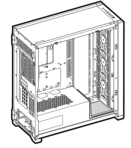
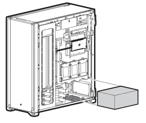
INSTALLING PSU
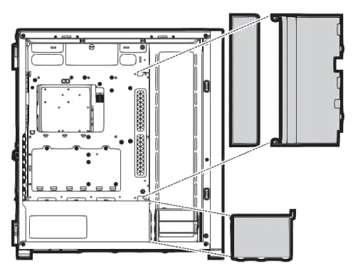
INSTALLING SSDS
Step 1: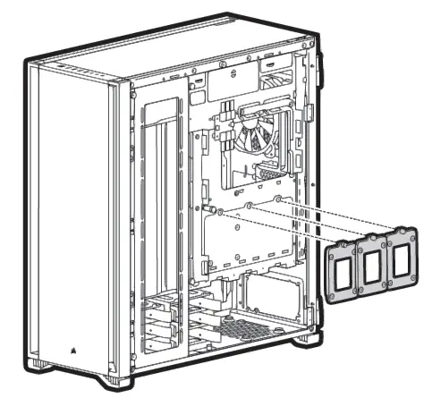
Step 2: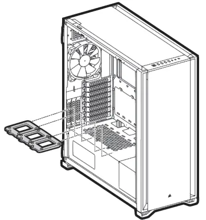
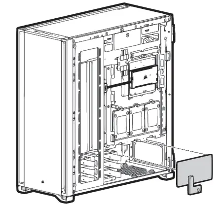
REMOVABLE PSU WINDOW
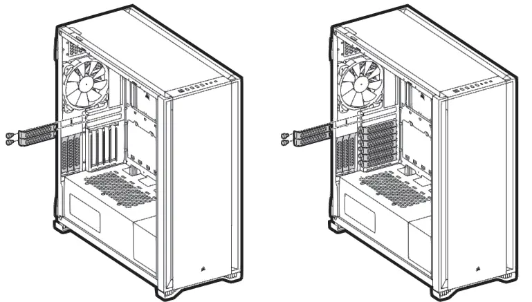
INSTALLING PCI-e CARDS
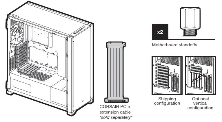
VERTICAL MOUNT GPU
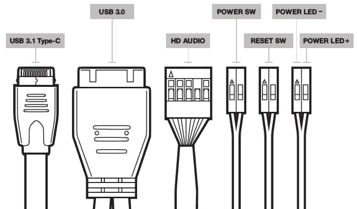
INSTALLING THE FRONT I/O CONNECTORS
ACCESSORIES IN THE BOX
FREQUENTLY ASKED QUESTIONS
- Does the polarity matter with the I/O panel’s power and reset header?
No, only the LED headers. - Who should I contact if I received my case damaged or one of the fans is no longer working?
Please go to support.corsair.com and request an RMA so that we can replace the damaged part(s). - Where can I mount a fan?
Fan mount locations Front 4x 120mm / 3x 140mm Top 3x 120mm / 3x 140mm Rear 120mm / 140mm Motherboard tray 4x 120mm
To learn more about this case visit the product page at corsair.com