BAYHSMT104-123 High Static Motor Kit with Odyssey TWE Air Handlers
Product Information
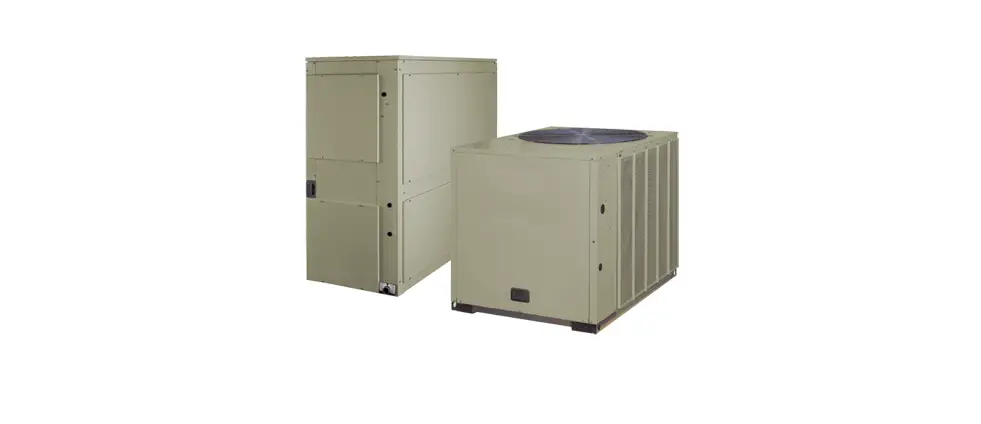
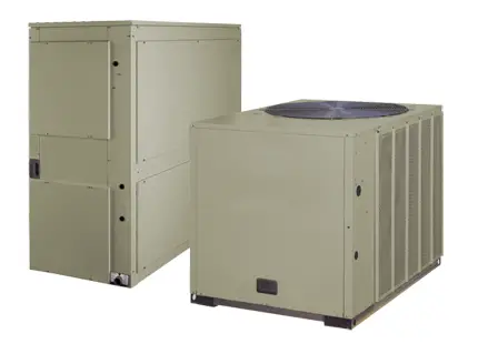
The High Static Motor Kit (BAYHSM T104-123) is designed to be used with Odyssey TWE Air Handlers. It is available in various kit numbers (BAYHSMT104-119) with different voltage, horsepower, and phase options. The kit is intended to be installed by qualified personnel only as it involves heating, ventilating, and air-conditioning equipment that can be hazardous and requires specific knowledge and training. Improper installation, adjustment, or alteration by an unqualified person could result in death or serious injury. Safety advisories and warnings are present throughout the manual to ensure personal safety and proper operation of the machine.
Product Usage Instructions
Before operating or servicing the High Static Motor Kit, read the manual thoroughly, and strictly observe all precautions mentioned in the literature and on the tags, stickers, and labels attached to the equipment. The following instructions must be followed while using the High Static Motor Kit:
- Ensure that only qualified personnel install and service the equipment.
- Follow all requirements for field wiring installation and grounding as described in NEC and your local/state/national electrical codes. Improperly installed and grounded field wiring poses fire and electrocution hazards.
- Wear proper Personal Protective Equipment (PPE) for the job being undertaken to protect yourself from potential electrical,
mechanical, and chemical hazards. - Select the appropriate High Static Motor Kit based on the air handler application as mentioned in Table 1 of the manual.
- Perform all field wiring by qualified personnel only to avoid hazards.
- Follow all safety advisories and warnings throughout the manual to ensure personal safety and proper operation of the machine.
SAFETY WARNING
Only qualified personnel should install and service the equipment. The installation, starting up, and servicing of heating, ventilating, and air-conditioning equipment can be hazardous and requires specific knowledge and training. Improperly installed, adjusted or altered equipment by an unqualified person could result in death or serious injury. When working on the equipment, observe all precautions in the literature and on the tags, stickers, and labels that are attached to the equipment.
Warnings, Cautions, and Notices
Read this manual thoroughly before operating or servicing this unit. Safety advisories appear throughout this manual as required. Your personal safety and the proper operation of this machine depend upon the strict observance of these precautions.
The three types of advisories are defined as follows:
- WARNING: Indicates a potentially hazardous situation which, if not avoided, could result in death or serious injury.
- CAUTION: Indicates a potentially hazardous situation which, if not avoided, could result in minor or moderate injury. It could also be used to alert against unsafe
- NOTICE: Indicates a situation that could result in equipment or property-damage only accidents.
Important Environmental Concerns
Scientific research has shown that certain man-made chemicals can affect the earth’s naturally occurring stratospheric ozone layer when released to the atmosphere. In particular, several of the identified chemicals that may affect the ozone layer are refrigerants that contain Chlorine, Fluorine and Carbon (CFCs) and those containing Hydrogen, Chlorine, Fluorine and Carbon (HCFCs). Not all refrigerants containing these compounds have the same potential impact to the environment. Trane advocates the responsible handling of all refrigerants-including industry replacements for CFCs such as HCFCs and HFCs.
Important Responsible Refrigerant Practices
Trane believes that responsible refrigerant practices are important to the environment, our customers, and the air conditioning industry. All technicians who handle refrigerants must be certified according to local rules. For the USA, the Federal Clean Air Act (Section 608) sets forth the requirements for handling, reclaiming, recovering and recycling of certain refrigerants and the equipment that is used in these service procedures. In addition, some states or municipalities may have additional requirements that must also be adhered to for responsible management of refrigerants. Know the applicable laws and follow them.
WARNING
Proper Field Wiring and Grounding Required!
Failure to follow code could result in death or serious injury. All field wiring MUST be performed by qualified personnel. Improperly installed and grounded field wiring poses FIRE and ELECTROCUTION hazards. To avoid these hazards, you MUST follow requirements for field wiring installation and grounding as described in NEC and your local/state/national electrical codes.
WARNING
Personal Protective Equipment (PPE) Required!
Failure to wear proper PPE for the job being undertaken could result in death or serious injury. Technicians, in order to protect themselves from potential electrical, mechanical, and chemical hazards, MUST follow precautions in this manual and on the tags, stickers, and labels, as well as the instructions below:
- Before installing/servicing this unit, technicians MUST put on all PPE required for the work being undertaken (Examples; cut resistant gloves/sleeves, butyl gloves, safety glasses, hard hat/bump cap, fall protection, electrical PPE and arc flash clothing). ALWAYS refer to appropriate Safety Data Sheets (SDS) and OSHA guidelines for proper PPE.
- When working with or around hazardous chemicals, ALWAYS refer to the appropriate SDS and OSHA/GHS (Global Harmonized System of Classification and Labeling of Chemicals) guidelines for information on allowable personal exposure levels, proper respiratory protection and handling instructions.
- If there is a risk of energized electrical contact, arc, or flash, technicians MUST put on all PPE in accordance with OSHA, NFPA 70E, or other country-specific requirements for arc flash protection, PRIOR to servicing the unit. NEVER PERFORM ANY SWITCHING, DISCONNECTING, OR VOLTAGE TESTING WITHOUT PROPER ELECTRICAL PPE AND ARC FLASH CLOTHING. ENSURE ELECTRICAL METERS AND EQUIPMENT ARE PROPERLY RATED FOR INTENDED VOLTAGE.
WARNING
Follow EHS Policies!
Failure to follow instructions below could result in death or serious injury.
- All Trane personnel must follow the company’s Environmental, Health and Safety (EHS) policies when performing work such as hot work, electrical, fall protection, lockout/tagout, refrigerant handling, etc. Where local regulations are more stringent than these policies, those regulations supersede these policies.
- Non-Trane personnel should always follow local regulations.
Copyright
This document and the information in it are the property of Trane, and may not be used or reproduced in whole or in part without written permission. Trane reserves the right to revise this publication at any time, and to make changes to its content without obligation to notify any person of such revision or change.
Trademarks
All trademarks referenced in this document are the trademarks of their respective owners.
General
The oversize motor kit should be used when additional air flow (CFM, and external static pressure) is required. Check Table 1 to ensure that the kit received is the correct one for the intended application.
Inspection
Inspect the shipping carton and its contents. Check for concealed damage before it is to be stored or used. If damaged, it should be reported to, and claims made against the transportation company. Replace damaged parts with authorized parts only.
Important: In accessory kits BAYHSMT105, 108, 110, 112 and 114 , the 3 Phase motors are dual rated at 208-230/460. Check the wiring diagram on the motor nameplate or the inside of the motor junction box to determine the correct wiring for the intended application.
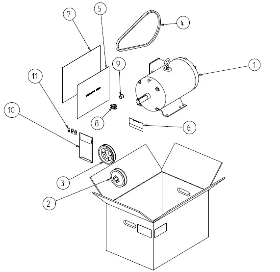
Figure 1. Parts list for high static motor kit
 MOTOR
MOTOR- MOTOR SHEAVE
- FAN SHEAVE
- BELT (EXCLUDED IN SOME KITS)
- INSTALLER’S GUIDE
- LABEL
- CLEAR BAG
- CONNECTOR
- BUSHING ENVELOPE (EXCLUDED IN SOME KITS)
- CONNECTOR WIRES) (EXCLUDED IN SOME KITS)
 MOTOR
MOTORTable 1. High static motor kit selection chart
| Kit No. | Description | Air Handler Application | |
| Volts/Hz/Ph | HP | Use With | |
| BAYHSMT104 | 230/60/1 | 1.5 | TWE060*1 |
| BAYHSMT105 | 230/460/60/3 380/50/3 | 1.5 1 | TWE051, TWE060*3, TWE060*4 |
| BAYHSMT106 | 575/60/3 | 1.5 | TWE060*W |
| BAYHSMT107 | 230/60/1 | 2 | TWE090*1 |
| BAYHSMT108 | 230/460/60/3 380/50/3 | 2 1.5 | TWE072*D, TWE072*3*****A00, TWE076, TWE090*3*****A00 |
| BAYHSMT109 | 575/60/3 | 2 | TWE072*W*****A00, TWE090*W*****A00 |
| BAYHSMT110 | 230/460/60/3 380/50/3 | 3 2 | TWE072*D, TWE072*3*****A00, TWE076, TWE090*3*****A00 |
| BAYHSMT111 | 575/60/3 | 3 | TWE072*W*****A00, TWE090*W*****A00 |
| BAYHSMT112 | 230/460/60/3 380/50/3 | 3 2 | TWE101, TWE120*3*****A00 |
| BAYHSMT113 | 575/60/3 | 3 | TWE120*W*****A00 |
| BAYHSMT114 | 230/460/60/3 380/50/3 | 3 2 | TWE126, TWE150*3*****A00 |
| BAYHSMT115 | 575/60/3 | 3 | TWE150*W*****A00 |
| BAYHSMT116 | 230/60/3 | 5 | TWE150*3*****A00 |
| BAYHSMT117 | 460/60/3 380/50/3 | 5 3.5 | TWE126, TWE150*3*****A00 |
| BAYHSMT118 | 575/60/3 | 5 | TWE150*W*****A00 |
| BAYHSMT119 | 230/60/3 | 5 | TWE180*3*****A00 |
| BAYHSMT120 | 460/60/3 380/50/3 | 5 3.5 | TWE156, TWE180*3*****A00 |
| BAYHSMT121 | 575/60/3 | 5 | TWE180*W*****A00 |
| Kit No. | Description | Air Handler Application | |
| Volts/Hz/Ph | HP | Use With | |
| BAYHSMT124 | 230/60/3 | 7.5 | TWE240*3*****A00 |
| BAYHSMT126 | 460/60/3 380/50/3 | 7.5 5 | TWE240*4*****A00 TWE201 |
| BAYHSMT123 | 575/60/3 | 7.5 | TWE240*W*****A00 |
Installation
WARNING
Hazardous Voltage w/Capacitors!
Failure to disconnect power and discharge capacitors before servicing could result in death or serious injury.
Disconnect all electric power, including remote disconnects and discharge all motor start/run capacitors before servicing. Follow proper lockout/tagout procedures to ensure the power cannot be inadvertently energized. For variable frequency drives or other energy storing components provided by Trane or others, refer to the appropriate manufacturer’s literature for allowable waiting periods for discharge of capacitors. Verify with a CAT III or IV voltmeter rated per NFPA 70E that all capacitors have discharged.
WARNING
Rotating Components!
Failure to disconnect power before servicing could result in rotating components cutting and slashing technician which could result in death or serious injury.
Disconnect all electric power, including remote disconnects before servicing. Follow proper lockout/tagout procedures to ensure the power can not be inadvertently energized.
- Ensure all power to the air handler has been disconnected and locked out.
- Remove the evaporator fan and control access panels.
- Disconnect all electrical motor leads from the motor.
- Loosen tension adjustment bolts on the motor mount and remove the fan belt and motor sheave.
- Remove the motor securing bolts and remove motor from the mount. If the oversize motor kit contains a fan sheave, remove the original sheave and install the one provided in the kit.
- Install oversize motor on mount. Secure with bolts removed in Step 5. Determine the correct air flow needed using blower performance charts. From Table 2, select the correct number of turns the motor sheave is to be opened.
Grease motor shaft and install motor sheave, (use sheave provided in kits, or if sheave is not provided, reuse the old one), as close to the motor bearing as possible without touching. Tighten both set screws (turns open and key way set screw) to 130 inch pounds. - Install new belt if provided in the kit, otherwise install belt that was removed in Step 4.
Adjust belt tension with adjusting bolts on the motor mount using instructions in Step 12.
NOTICE
Equipment Damage!
Proper adjustment of the fan belt is important to ensure optimal unit operation. Over or under tightening of the fan belt can result in belt slippage and excessive wear, bearing damage, sheave misalignment, and possible failure of fan motor mounts. - On new “A” belts, pressing down half way between the pulleys with a force of 6 pounds, there should be 1/4-inch deflection. After the belt has stretched to its normal operating length, a force of 3 to 4 pounds should deflect the belt 1/4-inch.
On new “B” belts, pressing down half way between the pulleys with force of 9 pounds, there should be 1/4-inch deflection. After the belt has stretched to its normal operating length, a force of 4 to 6 pounds should deflect the belt 1/4-inch.
Note: There will normally be a rapid drop in tension during the run-in period. Tension new belts with one half (1/2) greater initial deflection force than the maximum recommended operating deflection force. Tension should be checked frequently during the first day. The correct operating tension for a “V” belt fan drive is the lowest tension at which the belt will not slip under peak load conditions. - Check alignment of blower sheave with motor sheave using a straight edge and adjust blower sheave if necessary. Torque sheave set screw to 130 inch pounds.
WARNING
Live Electrical Components!
Failure to follow all electrical safety precautions when exposed to live electrical components could result in death or serious injury.
When it is necessary to work with live electrical components, have a qualified licensed electrician or other individual who has been properly trained in handling live electrical components perform these tasks. - Reconnect wire leads at the motor, using connection label on motor or unit wiring diagram.
- Secure wires so they do not make contact with any moving parts.
- Being careful not to touch any electrical or moving parts, close the unit disconnect switch and check the indoor fan for proper rotation, alignment and minimum vibration.
Note: If fan is rotating backwards, open the unit disconnect switch and reverse any two (2) of the motor leads on the motor terminals or pigtail leads. (Applies to 3 Phase only). - Once the proper rotation is verified, open the unit disconnect switch and
replace the control box cover and replace all panels. - Close the unit disconnect switch and check unit operation.
Table 2. High static fan motors – 50/60 Hz
| Model | Motor | Motor Sheave Turns Open | Nominal RPM |
| 0 | 1122 | ||
| 1 | 1066 | ||
| TWE051 | High Static Motor 1 HP (.75kW) | 2 3 | 1010 954 |
| 4 | 898 | ||
| 5 | 842 | ||
| 0 | 1346 | ||
| 1 | 1279 | ||
| TWE060 | High Static Motor 1.5 HP | 2 3 | 1212 1144 |
| 4 | 1077 | ||
| 5 | 1010 | ||
| 0 | 912 | ||
| 1 | 866 | ||
| TWE072 | High Static Motor 1.5 HP (1.13 kW) | 2 3 | 820 775 |
| 4 | 729 | ||
| 5 | 683 | ||
| 0 | 1094 | ||
| 1 | 1039 | ||
| TWE072 | High Static Motor 2 HP | 2 3 | 984 930 |
| 4 | 875 | ||
| 5 | 820 | ||
| 0 | 912 | ||
| 1 | 866 | ||
| TWE076 | High Static Motor 1.5 HP (1.13 kW) | 2 3 | 820 775 |
| 4 | 729 | ||
| 5 | 683 |
| Model | Motor | Motor Sheave Turns Open | Nominal RPM |
| 0 | 1094 | ||
| 1 | 1039 | ||
| TWE090 | High Static Motor 2 HP | 2 3 | 984 930 |
| 4 | 875 | ||
| 5 | 820 | ||
| 0 | 972 | ||
| 1 | 923 | ||
| TWE120 | High Static Motor 3 HP | 2 3 | 875 826 |
| 4 | 778 | ||
| 5 | 729 | ||
| 0 | 912 | ||
| 1 | 866 | ||
| TWE126 | High Static Motor 2 HP (1.5 kW) | 2 3 | 825 785 |
| 4 | 744 | ||
| 5 | 683 | ||
| 0 | 913 | ||
| 1 | 862 | ||
| TWE150 | High Static Motor 3 HP | 2 3 | 806 749 |
| 4 | 693 | ||
| 5 | 659 | ||
| 0 | 853 | ||
| 1 | 824 | ||
| TWE156 | High Static Motor 3.5 HP (2.6 kW) | 2 3 4 | 794 765 735 |
| 5 | 705 | ||
| 6 | 676 |
| Model | Motor | Motor Sheave Turns Open | Nominal RPM |
| 0 | 1024 | ||
| 1 | 989 | ||
| TWE180 | High Static Motor 5 HP | 2 3 4 | 953 918 882 |
| 5 | 847 | ||
| 6 | 811 |
Table 3. Ultra high static fan motors – 50/60 Hz
| Model | Motor | Motor Sheave Turns Open | Nominal RPM |
| TWE072 | Ultra High Static Motor 2 HP (1.5 kW) | 0 1 2 3 4 5 — | 1122 1034 946 859 771 683 — |
| TWE072 | Ultra High Static Motor 3 HP | 0 1 2 3 4 5 — | 1346 1241 1136 1030 925 820 — |
| Model | Motor | Motor Sheave Turns Open | Nominal RPM |
| TWE076 | Ultra High Static Motor 2 HP (1.5 kW) | 0 1 2 3 4 5 — | 1122 1034 946 859 771 683 — |
| TWE090 | Ultra High Static Motor 3 HP | 0 1 2 3 4 5 — | 1346 1241 1136 1030 925 820 — |
| TWE126 | Ultra High Static Motor 3.5 HP (2.6 kW) | 0 1 2 3 4 5 6 | 1014 979 944 909 874 838 803 |
| TWE150 | Ultra High Static Motor 5 HP | 0 1 2 3 4 5 6 | 1217 1175 1133 1091 1048 1006 964 |
| Model | Motor | Motor Sheave Turns Open | Nominal RPM |
| TWE201 | Ultra High Static Motor 5 HP (3.75 kW) | 0 1 2 3 4 5 6 | 1078 1036 993 950 907 864 822 |
| TWE240 | Ultra High Static Motor 7.5 HP | 0 1 2 3 4 5 6 | 1294 1243 1191 1140 1089 1037 986 |
Trane and American Standard create comfortable, energy efficient indoor environments for commercial and residential applications. For more information, please visit trane.com or americanstandardair.com.
Trane and American Standard have a policy of continuous product and product data improvement and reserve the right to change design and specifications without notice. We are committed to using environmentally conscious print practices.
ACC-SVN117G-EN 05 Mar 2022 Supersedes ACC-SVN117F-EN (Apr 2021)


