![]() Installation
Installation
Instructions
Part # 12302401.
– 65-72 Ford Galaxie Front HQ Shockwave, OEM Control Arms
Recommended Tools
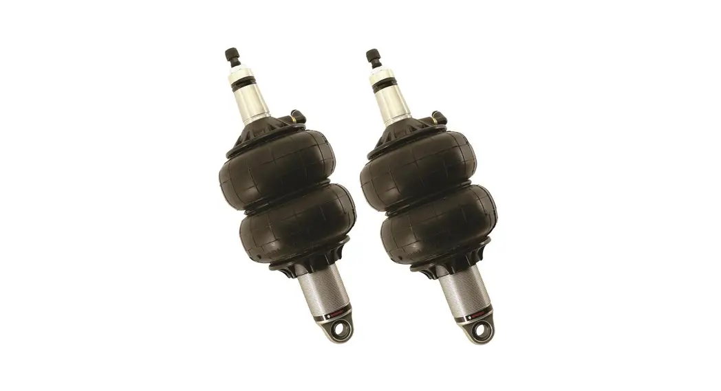
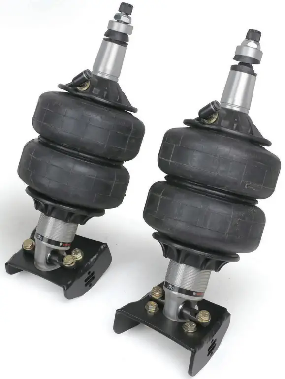
1000 Series Bellow, 2.0” Stud/Trunnion 2.9” Shock
Installation Instructions
ShockWave Dimensions:
Mount to Mount:
| Compressed: | 9.60” |
| Ride Height: | 11.00” |
| Extended: | 11.90” |
THE DELRIN BALL REQUIRES A 3/4” HOLE FOR THE FLANGE TO GO THROUGH. THIS CAN BE DRILLED WITH A UNIT.
www.ridetech.com ![]()
812-482-2932
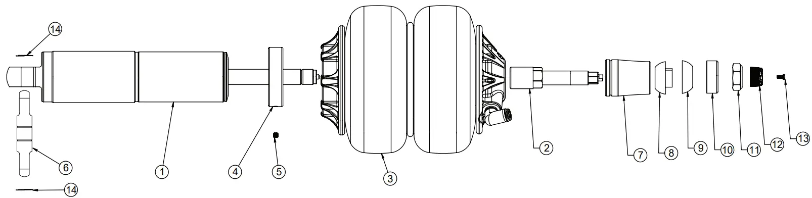
Major Components
…..In the box
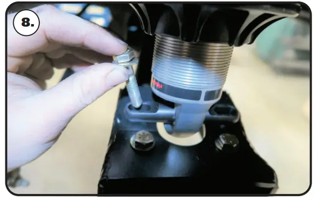
THE CONTROL ARM REINFORCEMENT MUST BE INSTALLED BETWEEN THE TRUNNION AND CONTROL ARM. See Image 8.
| Item # | Part # | Description | QTY |
| 1 | 982-10-802 | 2.9″ Stroke HQ Series Shock | 2 |
| 2 | 90009986 | 2″ Stud Top (Installed on Shock) – Includes Adjuster Knob & Screw | 2 |
| 3 | 24090199 | ‘1000 Series 6.5″ Double Convoluted AirSpring | 2 |
| 4 | 234-00-153 | AirSpring Locking Ring (Installed on shock) | 2 |
| 5 | 99055000 | Locking Ring Set Screw (Installed on shock) | 2 |
| 6 | 90002060 | Universal Trunnion | 4 |
| 7 | 90002312 | 2″ Aluminum Stud Top Base | 2 |
| 8 | 90001904 | Bottom Delrin Ball | 2 |
| 9 | 90001903 | Top Delrin Ball | 2 |
| 10 | 90001902 | Delrin Ball Aluminum Top Cap | 2 |
| 11 | 99562003 | 9/16″-18 Thin Nylok Nut | 2 |
| 12 | 210-35-120-0 | Adjuster Knob – (90009986 assembly) | 2 |
| 13 | 90009969 | #4-40 X 1/4″ SS, 18-8 Pan Head Torx Cap – (90009986 assembly) | 2 |
| 14 | 90001980 | Trunnion Locking Rings | 4 |
| 90003323 | Control Arm Reinforcement Plate (NOT SHOWN) | 2 | |
| 70012160 | 2″ Stud Top Metering Rod (installed in stud top) | 2 | |
| 90001994 | 5/8″ ID Bearing (installed in shock and eyelet) | 4 | |
| 90001995 | Bearing Snap Ring (installed in shock and eyelet) | 8 |
THE DELRIN BALL REQUIRES A 3/4” HOLE FOR THE FLANGE TO GO THROUGH. THIS CAN BE DRILLED WITH A UNIT.
Hardware List
In the box (Kit# 99010173)
| Part Number | Description | QTY |
| FRONT LOWER CONTROL ARM BRACE | ||
| 99311030 | 5/16″-18 x 1″ Hex Bolt | |
| 99312003 | 5/16″-18 NYLOK NUT | |
| 99313001 | 5/16″ SAE Flat Washer | 2 |
| Part Number | Description | QTY |
| TRUNNION TO CONTROL ARM | ||
| 99373006 | 3/8″ Split Lock Washer | 4 |
| 99373002 | 3/8″ SAE Flat Washer | 4 |
| 99371024 | 3/8″-16 x 1 3/4″ Hex Bolt | 4 |
ShockWave Installation
- Raise and support the vehicle at a safe, comfortable working height. Let the front suspension hang freely.
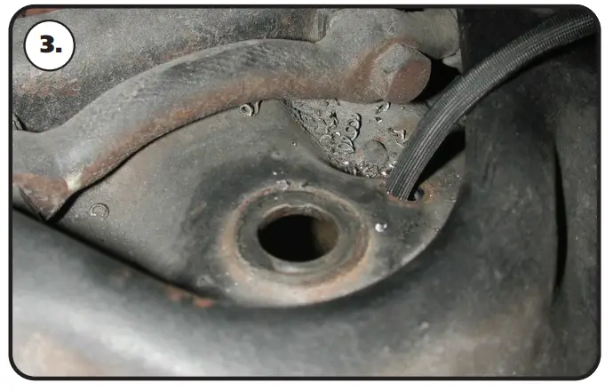
- Remove the coil spring and shock absorber. Refer to the factory service manual for the proper disassembly procedure.
- The upper shock hole needs to be drilled to 3/4”. A Unibit works well for drilling the hole.

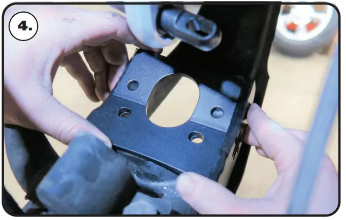
- Lay the lower shock mount on the lower control arm aligning the outer holes with the OEM shock mounting holes. This mount strengthens the control arm and relocates the bottom of the shock toward the engine.

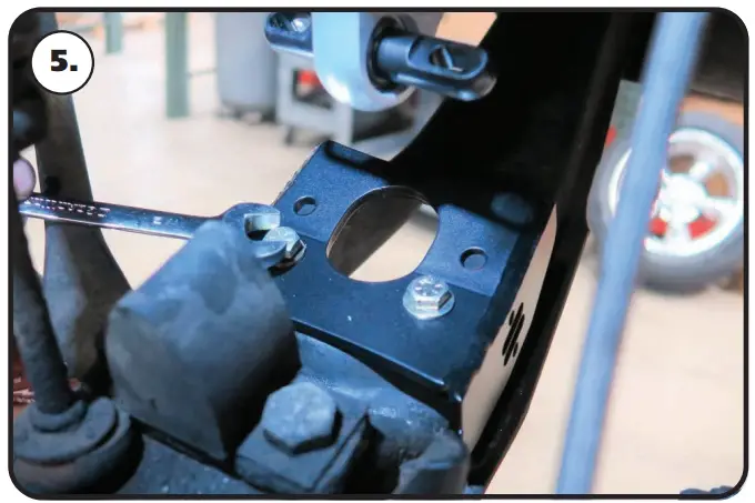
- Install a 5/16” fl at washer on each of (2) 5/16”-18 x 1” bolts. Insert the bolt/washer in the aligned holes of the lower mount and control arm. Install a 5/16” fl at washer & 5/16” nylon nut on each of the bolts. Torque to 25 ft-lbs.
Installation

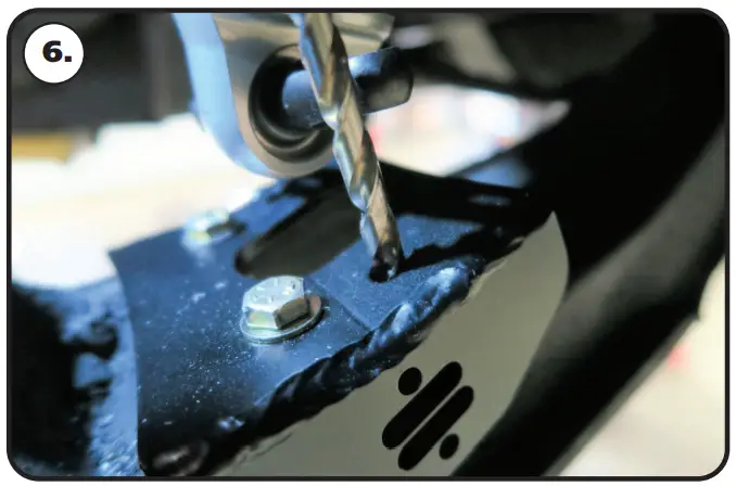
- Use a 5/16” drill bit to drill the (2) inner holes using the lower mount as a guide.
Note: The airline must also be routed at this time.
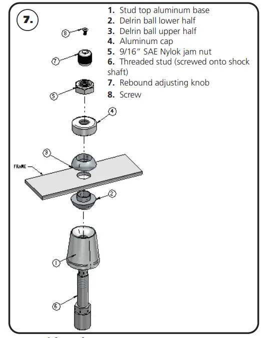
- Apply thread sealant to a 90-degree air fi thing and screw it into the top of the Shockwave. The air fi tting location can be rotated by twisting the bellow assembly separate of the shock. Place the Shockwave into the coil spring pocket with the stud sticking through the OEM shock hole. See assembly Diagram 7. OEM Shock hole must be drilled out to ¾”
1. Stud top aluminum base
2. Delrin ball lower half
3. Delrin ball upper half
4. Aluminum cap
5. 9/16” SAE Nylok jam nut
6. Threaded stud (screwed onto shock shaft)
7. Rebound adjusting knob
8. Screw
TIGHTENING THE TOP 9/16”-18 NUT: SNUG THE NUT DOWN AGAINST THE TOP CAP. YOU NEED TO BE ABLE TO ARTICULATE THE SHOCK BY HAND. WE TORQUE THE NUT TO 80 IN-LBS USING A 7/8” CROW’S FOOT WRENCH ON A TORQUE WRENCH.ShockWave Installation

Raise the lower arm up to the Shockwave and bolt them together using the 5/16” x 1 1/2” bolts, washers, & nylon nuts supplied with the ShockWaves. Torque to 25 ft-lbs.
- The best ride quality will occur around 5060% suspension travel; depending on vehicle weight this typically occurs around 100-110 psi.
NOTES:
WARNING: ATTEMPTING TO REMOVE THE AIR FITTING WILL DAMAGE IT AND VOID THE WARRANTY.
TIGHTENING THE TOP 9/16”-18 NUT: SNUG THE NUT DOWN AGAINST THE TOP CAP. YOU NEED TO BE ABLE TO ARTICULATE THE SHOCK BY HAND. WE TORQUE THE NUT TO 80 IN-LBS USING A 7/8” CROW’S FOOT WRENCH ON A TORQUE WRENCH.
You can clock the airfi tting location on the ShockWave by turning the AireSpring assembly of the shock. Make sure the fi thing doesn’t contact the frame. When cutting the airline, use a razor blade. The cut needs to be clean-cut and square for the airline to seal properly.
The Locking ring on the shock is NOT adjustable. These rings are set at the factory to optimize the AireSpring stroke with the shock stroke.
The care and feeding of your new ShockWaves
- Although the ShockWave has an internal bump stop, DO NOT DRIVE THE VEHICLE DEFLATED RESTING ON THIS BUMPSTOP. DAMAGE WILL RESULT. The internal bump stop will be damaged, the shock bushings will be damaged, and the vehicle shock mounting points may be damaged to the point of failure. This is a nonwarrantable situation.
- Do not drive the vehicle over a date or “topped out”. Over a period of time, the shock valve will be damaged, possibly to the point of failure. This is a nonwarrantable situation! If you need to raise your vehicle higher than the ShockWave allows, you will need a longer unit.
- The ShockWave is designed to give a great ride quality and to raise and lower the vehicle. IT IS NOT MADE TO HOP OR JUMP! If you want to hop or jump, hydraulics is a better choice. This abuse will result in bent piston rods, broken shock mounts, and destroyed bushings. This is a nonwarrantable situation.
- Do not let the ShockWave bellows rub on anything. Failure will result. This is a nonwarrantable situation.
- The ShockWave product has been fi eld tested on numerous vehicles as well as subjected to many different stress tests to ensure that there are no leakage or durability problems. Failures have been nearly nonexistent unless abused as described above. If the Shockwave units are installed properly and are not abused, they will last many, many years. ShockWave units that are returned with broken mounts, bent piston rods, destroyed bump stops or bushings, or abrasions on the bellows will not be warranted.
Shock Adjustment
Shock adjustment 101- Single Adjustable
Rebound Adjustment:
How to adjust your new shocks.
The rebound adjustment knob is located on the top of the shock absorber protruding from the eyelet.
You must fi rst begin at the ZERO setting, then set the shock to a soft setting of 20. 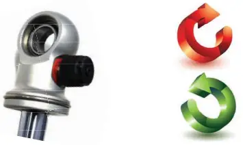
- Begin with the shocks adjusted to the ZERO rebound position (full stiff). Do this by rotating the rebound adjuster knob clockwise until it stops.
- Now turn the rebound adjuster knob counterclockwise 20 clicks. This sets the shock at 20. (settings 21-24 are typically too soft for street use).
Take the vehicle for a test drive.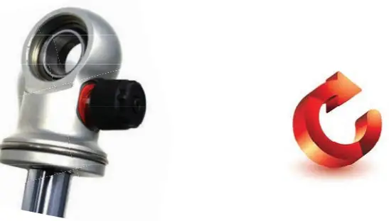
- if you are satisfi ed with the ride quality, do not do anything, you are set!
- if the ride quality is too soft increase the damping effect by rotating the rebound knob clockwise 3 clicks. CONTINUE ON TO THE NEXT PAGE.
Take the vehicle for another test drive.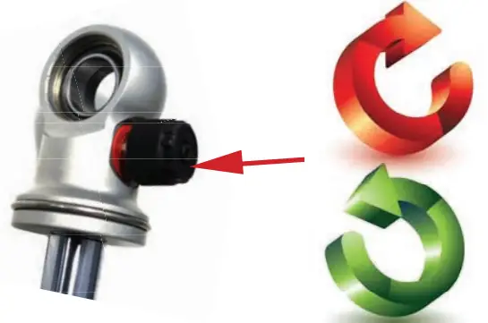
- if the vehicle is too soft increase the damping effect by rotating the rebound knob clockwise for 3 additional clicks.
- If the vehicle is too stiff rotate the rebound adjustment knob counter-clockwise 2 clicks and you are set!
Take the vehicle for another test drive and repeat the above steps until the ride quality is satisfactory.
- Note: One end of the vehicle will likely reach the desired setting before the other end. If this happens stop adjusting the satisfi ed end and keep adjusting the unsatisfi ed end until the overall ride quality is satisfactory.


