![]() Installation Instructions
Installation Instructions
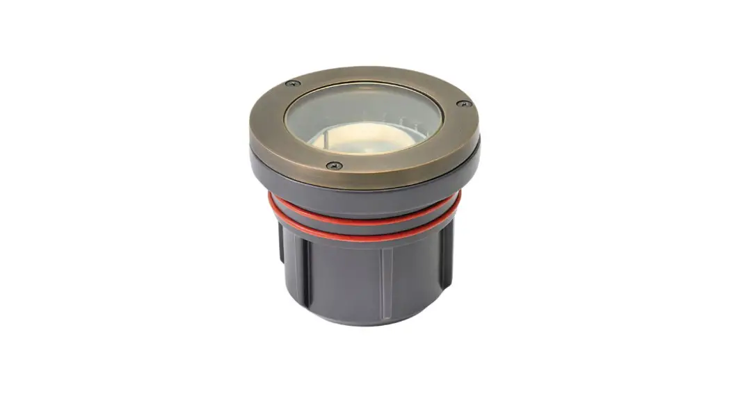
Well Light: Line Voltage | Item No. 55702
With included LED engine
55702 Well Light
LED Engine Optic Options
 |  |
* A ground flush to surface junction box or a thermal shrink tube kit can be used if a concrete pour kit is unavailable
![]() Start Here
Start Here
SAFETY WARNING: TURN POWER SUPPLY OFF DURING INSTALLATION. IF NEW WIRING IS REQUIRED, CONSULT A QUALIFIED ELECTRICIAN OR LOCAL AUTHORITY FOR CODE REQUIREMENTS.
IMPORTANT OPERATION NOTE: This luminaire is designed to be operated with Hinkley approved 120 volt AC systems.
NOTE: Luminaire can be placed in an area where a car may drive over the luminaire.
Luminaire Mounting (for typical in-ground mounting)
- To prevent electrical shock, disconnect power supply from electrical supply before installation or service.
- Luminaire may be directly buried in the ground. For concrete applica-tions, a removable burial sleeve and cap is included. Use cap when pouring concrete and discard after installation of the luminaire. (Make sure bottom hex nut is tight before burying fixture)
- In earth burial applications, the best way to extend fixture life is to use sand, gravel or any other material to facilitate drainage.
- Strip three wires (ACL – Black, ACN – White, GND – Green). Connect to main supply following local electrical code requirements.
Note: Wire is to be protected by routing in close proximity to the luminaire, fitting or next to a building structure such as a house or deck. Wiring should be buried a maximum of 6 inches (15.2 cm) in order to connect to main supply wire. The main supply wire must have its length cut off within 6 inches (15.2 cm) from a building, structure, luminaire or fitting.
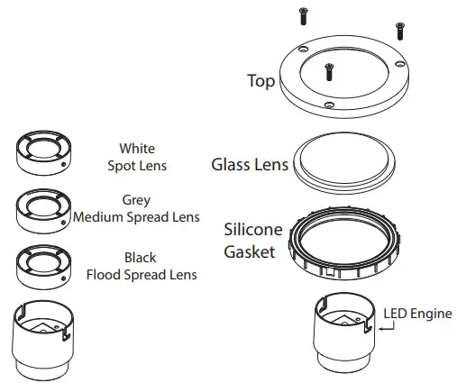
LED Engine Installation
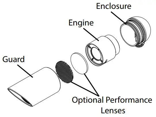
Three optics are included with the well light. A white spot lens, grey medium spread lens and a black hood lens . Place desired optic in the LED engine and twist to secure.
- To prevent electrical shock, turn off power supply from electrical supply before installation or service.
- Using a Phillips head screw driver, remove top screws and fixture top. Set these aside for use in reassembly.
- Remove silicone gasket and glass lens
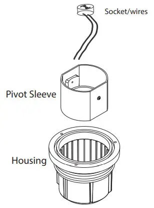
- Put the LED engine assembly, with attached socket, into the pivot sleeve. The engine sits in the sleeve freely.
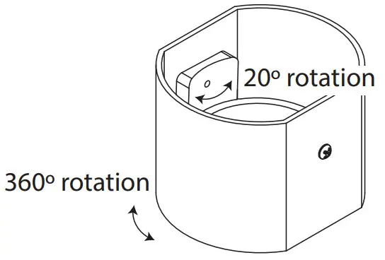
- Adjust the light direction by turning the pivot sleeve. The sleeve itself can be turned 360º and the pivot cup inside has a 20º adjustment. The screws on the pivot sleeve can be tightened to secure the cup in the correct angle.

- Return the silicone gasket and glass lens. Making sure the gasket isseated correctly. Make sure to align the cut-outs in the gasket to the screw holes
- Screw the fixture top back on.
| Drawing 1 – Engine Assembly | Drawing 2 LED wattage adjustment | Drawing 3 – Fixture Assembly Example |
 |  |  |
Assembly Instructions
Item No: 30G4SE-120V and 27G4SE-120![]() Start Here
Start Here
- In order to lamp the fixture you need to first assemble the engine.
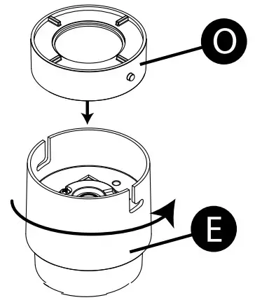
- Take the optic (O) and push it into the top of the engine (E) and twist it into place – see Drawing 1.
Note: Engine optic (O) comes in 3 types. - Hold the Lumacore with the Hinkley Logo so that its readable. The rotational switch (A) can be adjusted by your fingers or a small flat bladed screwdriver.
Rotate until the switch falls into a stop. For reference, the wattage settings are roughly akin to hours on a standard clock face. -See Drawing 2
1. After the engine is assembled, you can lamp the fixture by pushing the engine into place inside the enclosure.
2. Finish by reassembling the fixture – See Drawing 3
OUTPUT SWITCH SETTINGS
| 3 Watts, 3.2 VA, 260 Lumens | |
| 5 Watts, 5.3 VA, 350 Lumens | |
| 8 Watts, 7.8 VA, 475 Lumens | |
| 12 Watts, 12.4 VA, 750 Lumens |
| Black – Flood, 60° Noir – Inonder, 60° Negro – Inundar, 60° | White – Spot, 20° Blac – Place, 20° Blonco – Lugar, 20° | Grey – Medium Spread, 40° Gris – propagation moyenne, 40° Gris – propagación media, 40° |
HINKLEY 33000 Pin Oak Parkway, Avon Lake,
OH 44012 800.446.5539 / 440.653.5500
hinkley.com


