
EBYTE E103-W11 WiFi 6+BLE 5.1 Serial to WiFi Module
E103-W11 User Manual
WiFi 6+BLE 5.1 Serial to WiFi Module
Disclaimer
EBYTE reserves all rights to this document and the information contained herein products, names, logos and designs described herein may in whole or in part be subject to intellectual property rights. Reproduction, use, modification or disclosure to third parties of this document or any part thereof without the express permission of EBYTE is strictly prohibited. The information contained herein is provided “as is” and EBYTE assumes no liability for the use of the information. No warranty, either express or implied, is given, including but not limited, with respect to the accuracy, correctness, reliability and fitness for a particular purpose of the information. This document may be revised by EBYTE at any time. For most recent documents, visit www.ebyte.com.
Attention: Due to product version upgrade or other reasons, the contents of this manual may be changed. Ebyte Electronic Technology Co., Ltd. reserves the right to modify the contents of this manual without any notice or prompt. This manual is only used as a guide. Chengdu Ebyte Electronic Technology Co., Ltd. does its best to provide accurate information in this manual. However, Chengdu Ebyte Electronic Technology Co., Ltd. does not ensure that the contents of the manual are completely error-free. All statements in this manual , information and advice do not create any express or implied warranties.
Introduction
Brief Introduction
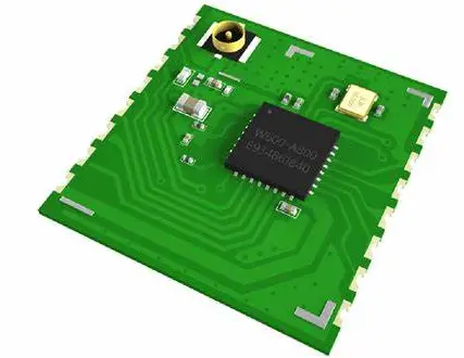
 E103-W11 is a cost-effective serial to Wi-Fi module, small size package, working in the 2.4~2.4835GHz frequency band. The module can use the serial port to send and receive data, which reduces the threshold for wireless applications. E103-W11 is a Bluetooth low energy BLE5.1 and Wi-Fi 802.11b/g/n/ax module. The main chip of the module integrates the hardware and software resources required for complete Wi-Fi and Bluetooth applications, and can support dual-role connections of AP and STA, as well as BLE low-power Bluetooth connections. An MCU running at speeds up to 240 MHz and built-in 512KB RAM enables the chip to support cloud connectivity.
Features
- Support WiFi 6 and Bluetooth Low Energy BLE 5.1;
- Available for global license-free ISM 2.4GHz frequency band;
- Support high-speed data transparent transmission;
- Support cloud server (MQTT);
- Support STA/AP mode, at least 8 devices’ access is supported in AP mode;
- Support network protocols: IPv4, TCP/ UDP;
- Support three Socket roles: TCP Server, TCP Client and UDP;
- Serial communication supported;
- AT commands supported;
- OTA upgrade supported;
- Support for Bluetooth distribution network;
- With superior MIMO technology。
Application
- Home security alarm and remote keyless entry
- Smart home appliances
- Wireless alarm security system
- Building automation solutions
- Industrial control
- Healthcare products
- Advanced Meter Reading Architecture (AMI)
- Environmental monitoring
Specification and parameter
RF Parameters
| RF parameters | Value | Remark |
| Working frequency | 2400MHz~2480MHz | Support ISM band |
| transmit power | 19.5dBm~20.5dBm | The software is adjustable, available for user self- development and configuration |
| Receive sensitivity | -87dBm | Air rate 500kbps |
| Wi-Fi version | IEEE 802.11 b/g/n/ax | Modulation technology |
| Air rate | 150Mbps | \ |
| Blocking power | 10dBm | The probability of burning at close range is small |
| Reference distance | 300m | Sunny and open, antenna gain 0dBi, onboard PCB antenna. |
Electrical parameters
| Main parameters | Performance | Remark | ||
| Min | Typical value | Max | ||
| Working voltage (V) | 3 | 3.3 | 3.6 | ≥5V guarantees output power, higher than 5.5V will permanently burn modules |
| I/O voltage | -0.3 | – | 3.6 | Voltage over 3.6V will cause permanent damage to module I/O |
| Communication level (V) | -0.3 | 3.3 | 3.6 | 5V TTL will permanently burn the module |
| Working temperature (℃) | -40 | – | +85 | Industrial design |
Hardware parameters
| Hardware parameters | Value | Remark |
| Packaging method | SMD | – |
| Interface | Stamp hole | Spacing 2.0mm |
| Communication interface | UART serial port | TTL level |
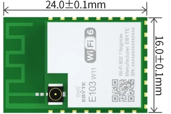
| Dimension | 16*24mm | — |
| Net weight | 1.3g | ±0.1g |
| RF interface | IPEX/stamp hole | Equivalent impedance is about 50Ω |
Size and Pin Definition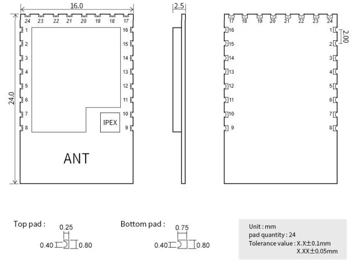
| Item | Pin name | I/O | Application |
| 1 | U0_TXD | 0 | AT serial port, TX of the module, connecting to RX of external TTL |
| 2 | U0_RXD | I | AT serial port, RX of the module, connecting to TX of external TTL |
| 3 | PWM | I/O | GPIO_NUM_4, it can be used as general GPIO by SYIO series instructions |
| 4 | MISO | I/O | GPIO_NUM_3, it can be used as general GPIO by SYIO series instructions |
| 5 | MOSI | O | Modulation serial port of E103-W11, LOG_TX, connecting to RX of external TTL |
| 6 | CS | I | Modulation serial port of E103-W11, LOG_RX, connecting to TX of external TTL |
| 7 | CLK | I/O | GPIO_NUM_0, it can be used as general GPIO by SYIO series instructions |
| 8 | GND | Ground wire, connected to the power reference ground | |
| 9 | GND | Ground wire, connected to the power reference ground | |
| 10 | RST | I | Chip reset input pin, low level reset |
| 11 | ADC | I/O | GPIO_NUM_20, it can be used as general GPIO by SYIO series instructions |
| 12 | IO1 | I/O | GPIO_NUM_1, it can be used as general GPIO by SYIO series instructions |
| 13 | IO2 | I/O | GPIO_NUM_2, it can be used as general GPIO by SYIO series instructions |
| 14 | DATA1 | I/O | GPIO_NUM_23, it can be used as general GPIO by SYIO series instructions |
| 15 | DATA0 | I/O | GPIO_NUM_22, it can be used as general GPIO by SYIO series instructions |
| 16 | H_CLK | I/O | GPIO_NUM_13, it can be used as general GPIO by SYIO series instructions |
| 17 | GND | Ground wire, connected to the power reference ground | |
| 18 | CMD | I/O | GPIO_NUM_21, it can be used as general GPIO by SYIO series instructions |
| 19 | DATA3 | I/O | GPIO_NUM_25, it can be used as general GPIO by SYIO series instructions |
| 20 | DATA2 | I/O | GPIO_NUM_24, it can be used as general GPIO by SYIO series instructions |
| 21 | WAKE | I | Chip reset input pin, low level reset. When using, RC reset pull-up is needed |
| 22 | IO3 | I/O | GPIO_NUM_16, it can be used as general GPIO by SYIO series instructions |
| 23 | GND | Ground wire, connected to the power reference ground | |
| 24 | VCC | Power input |
Recommended wire diagram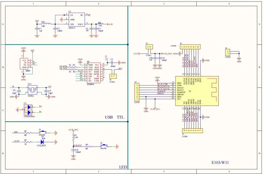
Note: The power supply must be within 3.0~3.6V. In order to ensure the stable operation of the module, it is recommended to select an external LDO with a current greater than 500mA.
Packaging Requirements
Note: Please use the product package provided on Ebyte official website for secondary development and design.
Quick Start
- E103-W11 is featured with easy usability. In order that users can quickly familiarize, this section will guide users to configure and communicate with this module in various modes through simple setting.
- All AT commands are used in the test process. To facilitate users’ quick connection, we have developed quick configuration software for users.
- In this section, tests will use configuration software and the module will echo the currently-sent commands, so that users can quickly know how to use AT command, thereby writing their own AT serial commands (Note: A newline is required after each AT command).
| Hardware used in this section: | |
| 1 | E103-W11 Wi-Fi module: 1pcs |
| 2 | E103-W11 Wi-Fi test board 1 pcs |
| 3 | Computer with Wi-Fi function 1 set |
| 4 | Router (replaceable by a mobile phone Wi-Fi hotspot) 1 set |
| Software that will be used in this section (All can be downloaded on Ebyte official website) | |
| 1 | E103-W11 network debugging assistant |
| 2 | BLE configuration APP |
| 3 | Serial Port Assistant Xcom |
Communication with server as TCP client
The following preparations are needed before doing the preliminary work
- Ensure that modules and server can exchange data via ping commands
- Module can operate normally
- E103-W11 network debugging assistant is needed
Access to network
AT+CWMODE=1,”s.y” //Switch the module mode to STA and save it to FLASH
AT+CWJAP=”Test11″,”12345678″,”s.y” //Connect the module to the WiFi with SSID “Test11” and password “12345678”
Switch to communication mode and connect to TCP Server
AT+CIPSTART=”TCP”,”192.168.1.100″,1001 //Establish a TCP connection with the tcp sever of 192.168.1.100. If transparent transmission once start is needed,
use the AT+SAVELINK command
AT+CIPMODE=1 //Switch to transparent transmission
AT+CIPSEND // Send data //After the module sends the ‘>’ symbol, transparent transmission is enabled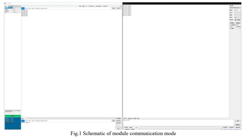 Use BLE for network configuration
Below preparations are needed
- Ensure the module is in STA mode
- Serial Port Assistant Xcom and BLE configuration APP are needed
- The following diagram 1 and diagram 2 are operation schematic
Switch working mode
AT+CWMODE=1,”s.y” //Switch the module mode to STA and save it to FLASH
Enable BLE broadcast
AT+BLEADVSTART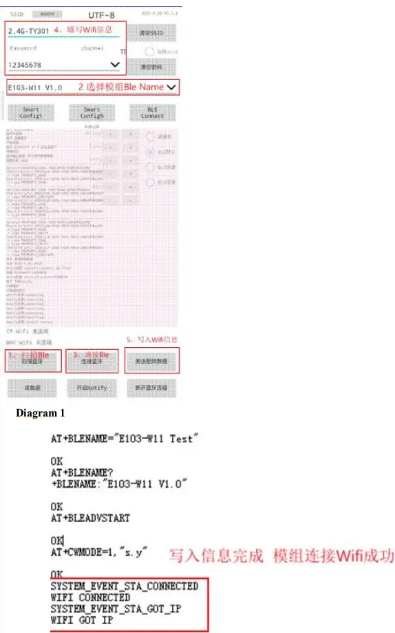
Description of BLE network configuration interface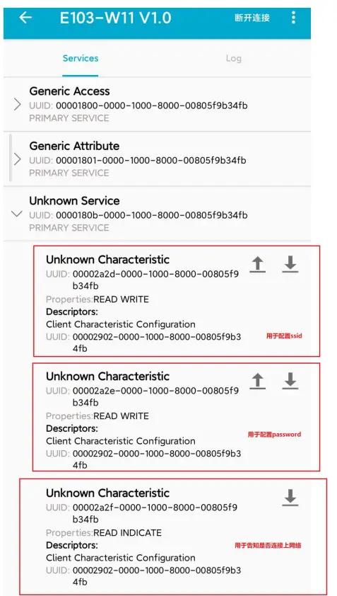
Instruction for network configuration
Network configuration role
| Serial No. | Remark |
| 1 | E103-W11 supports AP mode as a physical connection role (equivalent to a router). In STATION mode (it is equivalent to a Wi-Fidevice), access of up to 8 Wi-Fi devices in APmode is supported. |
| 2 | E103-W11 includes TCPServer, TCPClientand UDPas Socketrole. In TCPServer modeas Socketrole. Connection to 5 Socketsissupported. In caseof TCP-basedconnectionmechanism, if connected for a longtime is needed, pleaseuse TCP heartbeat packets. |
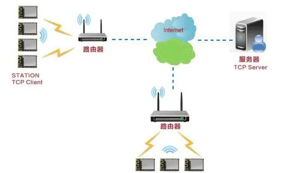
Network configuration model
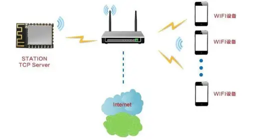
| The module realize connection and communication between a TCP Client and a remote server in STATION mode (typical application) |
| The model can meet the application requirements of home Internet of things, intelligent meter reading, real-time monitoring, etc. The module is available for real-time exchange data with the network server. User can perform various operations on the module in real time by interacting with the network server. |
|
|
| The module enables a connection between the TCP Server and the Wi-Fi device in STATION mode |
| This networking model is similar to the first one. The difference is that the module enables a TCP Server instead of a TCP Client in STATION mode. Under the condition of networking, this mode can support up to 5 remote device connections. |
|
|
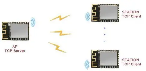
| One module enables TCP Server in AP mode, and other modules enables TCP Client to communicate with each other in STATION mode |
| This networking model can be referred to as intra-module networking. A module in AP mode can be connected to a maximum of 8 STATIONs, that is, there are up to 9 module devices in the network. Under the condition that the internal networking is completed, the TCP Server can be established on any module, and the remaining 8 modules can use the TCP Client to communicate with it (but the number of clients that can access the TCP server at the same time cannot exceed 5). |
|
|
Hardware design
- It is recommended to use a DC regulated power supply to supply power to the module, the power supply ripple coefficient should be as small as possible, and the module should be grounded reliably
- Please pay attention to the correct connection of the positive and negative poles of the power supply, such as reverse connection may cause permanent damage to the module
- Please check the power supply to ensure that it is between the recommended power supply voltages. If it exceeds the maximum value, the module will be permanently damaged;
- Please check the stability of the power supply, the voltage should not fluctuate greatly and frequently;
- When designing the power supply circuit for the module, it is often recommended to reserve more than 30% of the margin, so that the whole machine can work stably for a long time;
- The module should be kept as far away as possible from the power supply, transformer, high-frequency wiring and other parts with large electromagnetic interference;
- High-frequency digital traces, high-frequency analog traces, and power traces must avoid the underside of the module. If it is absolutely necessary to pass under the module, assuming that the module is soldered on the Top Layer, ground copper is placed on the Top Layer of the contact part of the module (all layers).
- Copper and well grounded), must be close to the digital part of the module and routed on the Bottom Layer;
- Assuming that the module is soldered or placed on the Top Layer, it is also wrong to arbitrarily route wires on the Bottom Layer or other layers, which will affect the stray and receiving sensitivity of the module to varying degrees;
- Assuming that there are devices with large electromagnetic interference around the module, it will also greatly affect the performance of the module. It is recommended to stay away from the module according to the intensity of the interference. If the situation allows, appropriate isolation and shielding can be done;
- Assuming that there are traces with large electromagnetic interference around the module (high-frequency digital, high- frequency analog, power traces), the performance of the module will also be greatly affected. It is recommended to stay away from the module according to the intensity of the interference. Proper isolation and shielding;
- If the communication line uses a 5V level, a 1k-5.1k resistor must be connected in series (not recommended, there is still a risk of damage); Try to stay away from some TTL protocols whose physical layer is also 2.4GHz, for example: USB3.0;
- The antenna installation structure has a great influence on the performance of the module. Make sure that the antenna is exposed, preferably vertically upward.
- When the module is installed inside the case, a high-quality antenna extension cable can be used to extend the antenna to the outside of the case
- The antenna is not allowed to be installed inside the metal shell, which will greatly reduce the transmission distance.
Frequently Asked Questions
The transmission distance is not ideal
- When there is a straight line communication obstacle, the communication distance will be attenuated accordingly;
- Temperature, humidity, and co-frequency interference will increase the communication packet loss rate;
- The ground absorbs and reflects radio waves, and the test effect is poor near the ground;
- Sea water has a strong ability to absorb radio waves, so the seaside test effect is poor;
- If there are metal objects near the antenna or placed in a metal shell, the signal attenuation will be very serious;
- The power register is set incorrectly, and the air rate is set too high (the higher the air rate, the closer the distance);
- The low voltage of the power supply at room temperature is lower than the recommended value, the lower the voltage, the lower the power output;
- The poor matching degree of the antenna and the module or the quality of the antenna itself.
Module is easy to damage
- Please check the power supply to ensure that it is within the recommended power supply voltage. If it exceeds the maximum value, it will cause permanent damage to the module;
- Please check the stability of the power supply, and the voltage cannot fluctuate significantly and frequently;
- Please ensure that the installation and use process is anti-static, and high-frequency components are electrostatically sensitive; Please ensure that the humidity should not be too high during installation and use, and some components are humidity sensitive devices;
- If there is no special requirement, it is not recommended to use at too high or too low temperature.
Bit error rate is too high
- There is co-frequency signal interference nearby, stay away from the interference source or modify the frequency and channel to avoid interference;
- If the power supply is not ideal, it may also cause garbled characters. Be sure to ensure the reliability of the power supply; Poor quality or too long extension lines and feeders will also cause high bit error rates.
Welding Operation Guidance
Reflow temperature
| Profile Feature | Sn-Pb Assembly | Pb-Free Assembly | |
| Preheat/ heat preservation | Min preheating temp. (Tsmin) | 100℃ | 150℃ |
| Max preheating temp. (Tsmax) | 150℃ | 200℃ | |
| Preheating time (Tsmin~Tsmin) | 60-120 sec | 60-120 sec | |
| Average ramp-up rate (TL~Tp) | 3℃/second max | 3℃/second max | |
| Liquidous Temperature (TL) | 183℃ | 217℃ | |
| Time Maintained Above TL | 60~90 sec | 60~90 sec | |
| Peak temperature Tp | Do not exceed the temperature stated on the “damp sensitivity” label. | Do not exceed the temperature stated on the “damp sensitivity” label. | |
| See the figure below for time (Tp) within 5°C of the specified grading temperature (Tc) | 20 sec | 30秒sec | |
| Average ramp-down rate (Tp~TL) | 6℃/second max | 6℃/second max | |
| Time 25℃ to peak temperature | 6 minutes max | 8 minutes max | |
| ※The peak temperature (Tp) tolerance definition of the temperature profile is the upper limit | |||
Reflow profile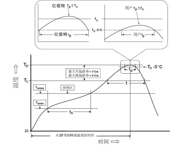
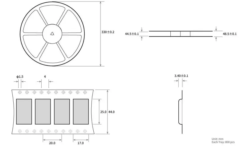
Batch product packaging
Revision history
| Version | Date | Description | Issued by |
| V1.0 | 2022-10-18 | Initial version | Hao |
About us
 Hoteline: 400-330-990 Company Tel: 028-61399028 Technical support: [email protected]
Official website: https://www.ru-ebyte.com
Address: B5 Mould Park, 199# Xiqu Ave, High-tech District, Sichuan, China.


