 HiteVision Wi-Fi 6 Module
Product version modification records
| Version | Modified Content Description | Date | Modifier | Approver |
| V1.0 | First Edition | March 15, 2022 | Zhi-yong liu | Zhang Chaobing |
Product overview
As AZ832-HN(or AZ833-HN) network module Customized board for commercial display screen ,this product builds environment network foundation and service for Business display screen Internet access. The product integrates two wireless network cards,,The product supports wireless access and hotspot release functions。Then,at the same time to provide larger cable and WIFI6 dual-band wireless (integrated bluetooth 5.2) data communication, realize the multipath access to the Internet access Domestic output at the same time WIFI5 hotspot is used to projection screen and other wireless LAN using equipment。
Technical specifications of products
| Equipment model | AZ832-HN |
| CPU Group | RTL8367N-VB USBHUB WIFI MODULE |
| Product Interfaces | 2 Gigabit Ethernet interfaces |
| European connector(Connect to Android) | |
| USB HUB (Uses 1 minute 4 USB2.0) | |
| WIFI6 module 1: RTL8852BU(Integrated BT5.2 function) WIFI5 module 2: RTL8811CU-CG | |
| Wireless Rate | WIFI6 module 1:[email protected]/2*2 11AX;1201Mbps@5GHz/2*2 11AX WIFI5 module 2: [email protected]/1*1 11N;433Mbps@5GHz/1*1 11AC |
| Ante nna Gain | Integrated external antenna ,Gain value 2.4GHz:3.82dBi; U-NII-1:3.87 dBi; U-NII-3:3.85 dBi |
| Protection level | surge signal :Common mode + / – 2 kv, class B |
| ESD protection level | Contact discharge ±6KV, air discharge ±8KV, class B |
| Environmental conditions | Operating temperature: 0℃ to 45℃; Storage temperature: -40℃ to 70℃ Working humidity: 10% to 90%RH does not condense; Storage humidity: 5% to 90%RH (Does not condense) |
Product design
Interface and specification:
| Part name | Specification description | Remark |
| Switch | Using rtl8367 chip | Used for communication between LAN devices, such as Android and OPS |
| Wireless Model 1 | 2.4G&5GHz 802.11a/b/g/n/ac/ax +BT5.2 | The main function is wireless reception and Internet access; wi-fi6 standard |
| Wireless Model 2 | 2.4G&5GHz 802.11a/b/g/n/ac | For product hotspots, wi-fi5 standard |
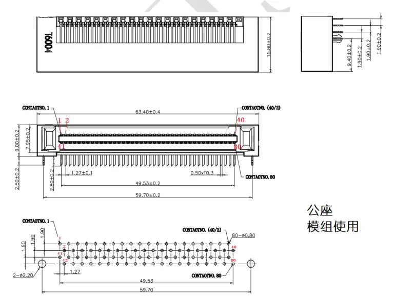
| European connector | 80pin connector | The interface supports 12V power supply and Integrated 3 LAN interfaces |
| RJ45 | Fully shielded metal RJ45, Gigabit interface | The interface functions are Intelnet and LAN |
| antenna | Integrated rod antenna, Gain value 5dBi | Omnidirectional antenna |
European connector
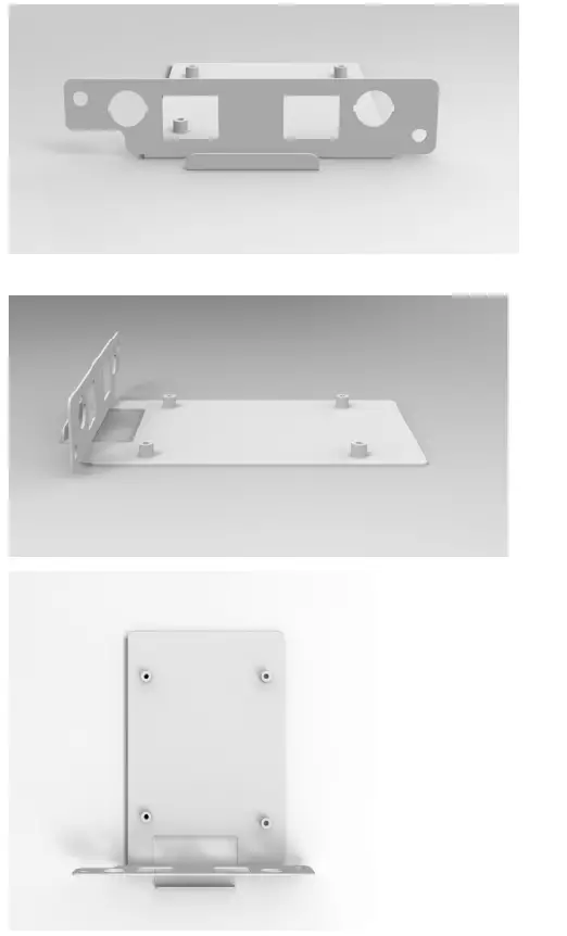
PCBA main board structure
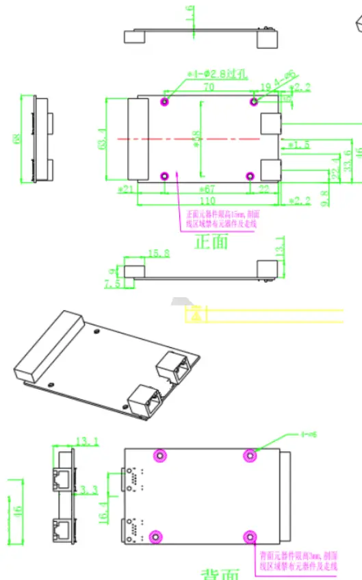
Chassis structure
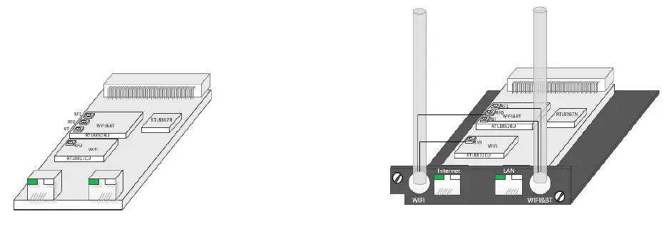
Product diagram
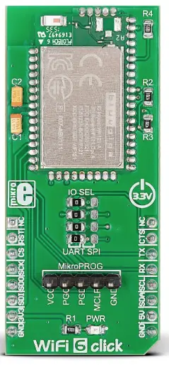
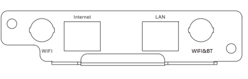
 Panel silk screen
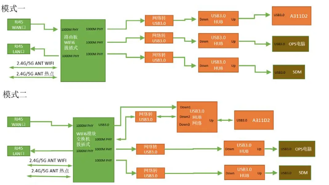
Functional block diagram
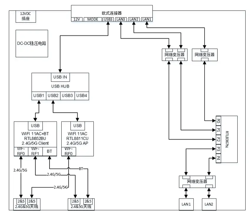
System scheme diagram
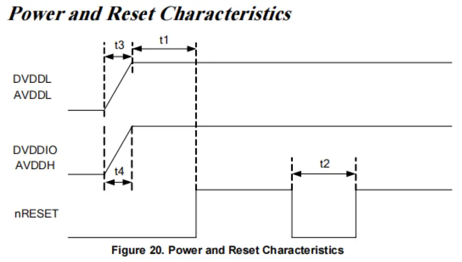
Electrical characteristics
FCC Statement
This device complies with part 15 of the FCC rules. Operation is subject to the following two conditions:
(1) this device may not cause harmful interference, and (2) this device must accept any interference received, including interference that may cause undesired operation. Changes or modifications not expressly approved by the party responsible for compliance could void the user’s authority to operate the equipment.
NOTE: This equipment has been tested and found to comply with the limits for a Class B digital device, pursuant to part 15 of the FCC Rules. These limits are designed to provide reasonable protection against harmful interference in a residential installation. This equipment generates uses and can radiate radio frequency energy and, if not installed and used in accordance with the instructions, may cause harmful interference to radio communications. However, there is no guarantee that interference will not occur in a particular installation. If this equipment does cause harmful interference to radio or television reception, which can be determined by turning the equipment off and on, the user is encouraged to try to correct the interference by one or more of the following measures:
- Reorient or relocate the receiving antenna.
- Increase the separation between the equipment and receiver.
- Connect the equipment into an outlet on a circuit different from that to which the receiver is connected.
- Consult the dealer or an experienced radio/TV technician for help.
Radiation Exposure Statement
This equipment complies with FCC radiation exposure limits set forth for an uncontrolled environment. This equipment should be installed and operated with minimum distance 20cm between the radiator and your body. This transmitter must not be co-located or operating in conjunction with any other antenna or transmitter. Country Code selection feature to be disabled for products marketed to the US/Canada. This device is intended only for OEM integrators under the following conditions:
- The antenna must be installed such that 20 cm is maintained between the antenna and users, and
- The transmitter module may not be co-located with any other transmitter or antenna,
Important Note:
This modular transmitter is only FCC authorized for FCC Part 15.247&15.407 as listed on the grant, and the host product manufacturer is responsible for compliance to any other FCC rules that apply to the host not covered by the modular transmitter grant of certification. The final host product still requires Part 15 Subpart B compliance testing with the modular transmitter installed.
End Product Labeling
If the FCC identification number is not visible when the module is installed insideanother device, then the outside of the device into which the module is installed must also display a label referring to the enclosed module. This exterior label can use wording such as the following: Contains Transmitter Module FCC ID:2ACYT-AZ832
Information that must be placed in the end user manual:
The OEM integrator has to be aware not to provide information to the end user regarding how to install or remove this RF module in the user’s manual of the end product which integrates this module.The end user manual shall include all required regulatory information/warning as show in this manual.
OEM integration instructions:
This device is intended only for OEM integrators under the following conditions: The transmitter module may not be co-located with any other transmitter or antenna. The module shall be only used with the external antenna(s) that has been originally tested and certified with this module. As long as the conditions above are met, further transmitter test will not be required. However, the OEM integrator is still responsible for testing their end-product for any additional compliance requirements required with this module installed (for example, digital device emissions, PC peripheral requirements, etc.).
Validity of using the module certification:
In the event that these conditions cannot be met (for example certain laptop configurations or co-location with another transmitter), then the FCC authorization for this module in combination with the host equipment is no longer considered valid and the FCC ID of the module cannot be used on the final product. In these circumstances, the OEM integrator will be responsible for re-evaluating the end product (including the transmitter) and obtaining a separate FCC authorization.


