![]() Electronics AW-01 802.11b-g-n Wi-Fi Module
Electronics AW-01 802.11b-g-n Wi-Fi Module
User Manual
Overview
This article describes the meaning, syntax, response, and examples of the AT commands of the Starcom AW-01 series products.
The command set is mainly divided into system control AT commands, Wi-Fi function AT commands, and TCP/IP related AT commands.
Disclaimer and copyright notice
The information in this article, including the URL address for reference, is subject to change without notice. The document is provided “as is” and does not bear any guarantee responsibility, including any guarantee for merchantability, suitability for a specific purpose or non-infringement, and any guarantee mentioned elsewhere in any proposal, specification or sample. This document does not take any responsibility, including the responsibility for infringement of any patent rights caused by the use of the information in this document. This document does not grant any license for the use of intellectual property rights in estoppel or other ways, whether express or implied. The Wi-Fi Alliance member logo is owned by the Wi-Fi Alliance. All brand names, trademarks, and registered trademarks mentioned in this article are the property of their respective owners, and it is hereby declared.
Update record
| Data | Version | Author | update content |
| 2020.07.08 | V1.0 | TT | initial version |
General Description
AW-01 is a UART-WiFi module based on Lianshengde W600 developed by Shenzhen Xingtong Zhilian Technology Co., Ltd. This series of modules supports standard 802.11 b/g/n protocol and has a built-in complete TCP/IP protocol stack.
AW-01 Series Modules integrate Cortex-M3 CPU, Flash, RF Transceiver, CMOS PA, and Baseband control. It applies multi interfaces such as SDIO, SPI, UART, GPIO, I²C, PWM, I²S, 7816 etc. It applies multi encryption and decryption protocol such as PRNG (Pseudo Random Number Generator), SHA1, MD5, RC4, DES, 3DES, AES, CRC, etc.
AW-01 Series Modules are an embedded Wi-Fi SoC Module which is complying with IEEE802.11b/g/n (1T1R) international standard and supports multi-interface, multi-protocol. It can be easily applied to smart appliances, smart homes, health care, smart toy, wireless audio & video, industrial, and other IoT field.
Product Features
- Integrated 288KB RAM;
- Integrated 1MB FLAS
- Integrated 2 UART interface, support RTS/CTS, baud rate: 1200bps~2Mbp
- Integrated one high-speed SPI controller, operating frequency: 0~50MH
- Integrated I²S controller, support full-duplex and codec from 32KHz to 192KH
- Integrated one I²C controller, support data transmission rate 100/400Kbp
- Integrated PWM controller, support 5 channel PWM output or 2 channels PWM input capture. Max output frequency is 20MHz and max input frequency is 20MHz;
- Integrated 7816 interface, support ISO-7816-3 T=0/1, EVM2000 protocol, and UART protocol
- Integrated encrypted hardware accelerator, support PRNG(Pseudo Random Number Generator), SHA1, MD5, RC4, DES, 3DES, AES, CRC;
- Support 20/40M bandwidth;
- Support Keil and eclipse development environment;
Module Interface
2.1 Package Size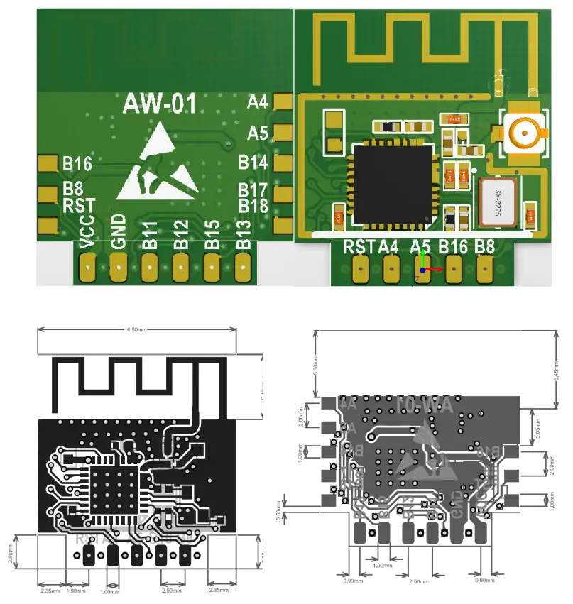
| Module | Package | Antenna | Size | layer |
| AW-01 | SMT14\DIP-11 | PCB | 16.5*17.8*3(±0.2)mm | 2 |
2.2 Pin Definition
| Num | Pin name | Type | Explain |
| 1 | VCC | P | IO 3.3V |
| 2 | PB8 | I/O | PWM5、H_SPI_CK、SDIO_CK、I²S_M_SCL、GPIOPB_8 |
| 3 | GND | P | GND |
| 4 | PB16 | I/O | PWM_2、SPI(M/S)_CK、I²S_S_RL、GPIOPB_16 、HSPI_CK |
| 5 | PB11 | I/O | H_SPI_DI、SDIO_DAT2、I²C_SCL、GPIOPB_11 、UART1_RX |
| 6 | PA5 | I/O | PWM_0、SPI(M/S)_DI、I²S_M_EXTCLK、GPIOPA_5 、UART0_RX |
| 7 | PB12 | I/O | H_SPI_DO、SDIO_DAT3、I²C_DAT、GPIOPB_12 、UART1_TX |
| 8 | PA4 | I/O | PWM_4、SPI(M/S)_DO、I²S_M_SCL、GPIOPA_4、UART0_TX |
| 9 | PB15 | I/O | PWM_3、SPI(M/S)_CS、I²S_S_SCL、GPIOPB_15 、H_SPI_CS |
| 10 | RST | I | RESET |
| 11 | PB13 | I/O | PWM_2、I²C_SCL、SDIO_CMD、GPIOPB_13 |
| 12 | PA4 | I/O | PWM_4、SPI(M/S)_DO、I²S_M_SCL、GPIOPA_4、UART0_TX |
| 13 | PA5 | I/O | PWM_0、SPI(M/S)_DI、I²S_M_EXTCLK、GPIOPA_5 、UART0_RX |
| 14 | PB14 | I/O | PWM_4、I²C_DAT、I²S_S_SDA、GPIOPB_14 、H_SPI_INT |
| 15 | PB17 | I/O | PWM_1、SPI(M/S)_DI、UART1_RX、GPIOPB_17 、H_SPI_DI |
| 16 | PB18 | I/O | PWM_0、SPI(M/S)_DO、UART1_TX、GPIOPB_18、H_SPI_DO |
| 17 | PB16 | I/O | PWM_2、SPI(M/S)_CK、I²S_S_RL、GPIOPB_16 、HSPI_CK |
| 18 | PB8 | I/O | PWM5、H_SPI_CK、SDIO_CK、I²S_M_SCL、GPIOPB_8 |
| 19 | RST | I | RESET |
Electrical characteristics
3.1 Limit parameter
Table 3-1 Limit parameter
| parameter | Name | Main | Type | MAX | Unit |
| Supply Voltage | VDD | 3.0 | 3.3 | 3.6 | V |
| Input logic level low | VIL | -0.3 | 0.8 | V | |
| Input logic level hight | VIA | 2.0 | VDD+0.3 | V | |
| Input pin Capacitance | Ipad | 2 | pF | ||
| Output logic level low | VOL | 0.4 | V | ||
| Output logic level hight | VEOH | 2.4 | V | ||
| Maximum Driving Capability | IMAX | 24 | mA | ||
| Storage temperature range | TOUR | -40℃ | +125℃ | ℃ | |
| Operating Temperature Range | TOUR | -40℃ | +85℃ | ℃ |
3.2 Transmit Power
Table 3-2 Transmit Power
| Mode | Type | Unit |
| Send IEEE802.11b, CCK 11Mbps, POUT = +19 dBm | 230 | mA |
| Send IEEE802.11g, OFDM 54Mbps,POUT = +13.5 dBm | 210 | mA |
| Send IEEE802.11n, OFDM MCS7, POUT = +12dBm | 210 | mA |
| Receive IEEE802.11b/g/n | 100-110 | mA |
3.3 Wi-Fi Radio Characteristics
| Parameters | Type | Unit |
| Input frequency | 2.4GHz~2.4835MHz | |
| Nominal power | ||
| 72.2 Mbps PA | 12 | dBm |
| 11b Mode PA | 19 | dBm |
| Sensitivity | ||
| DSSS, 1 Mbps | -95 | dBm |
| CCK, 11 Mbps | -86 | dBm |
| OFDM, 6 Mbps | -89 | dBm |
| OFDM, 54 Mbps | -73 | dBm |
| HT20, MCS0 | -89 | dBm |
| HT20, MCS7 | -71 | dBm |
| HT40, MCS0 | -85 | dBm |
| HT40, MCS7 | -68 | dBm |
| Adjacent Channel Rejection | ||
| OFDM, 6 Mbps | 32 | dB |
| OFDM, 54 Mbps | 15 | dB |
| HT20, MCS0 | 29 | dB |
| HT20, MCS7 | 10 | dB |
Hardware Guide
4.1 Typical Applications
Note: You can’t use USB to TTL 3.3V or 5V power supply, it is recommended to use two dry batteries or after conversion through the LDO 3.3V, it is strongly recommended to buy a new development board.
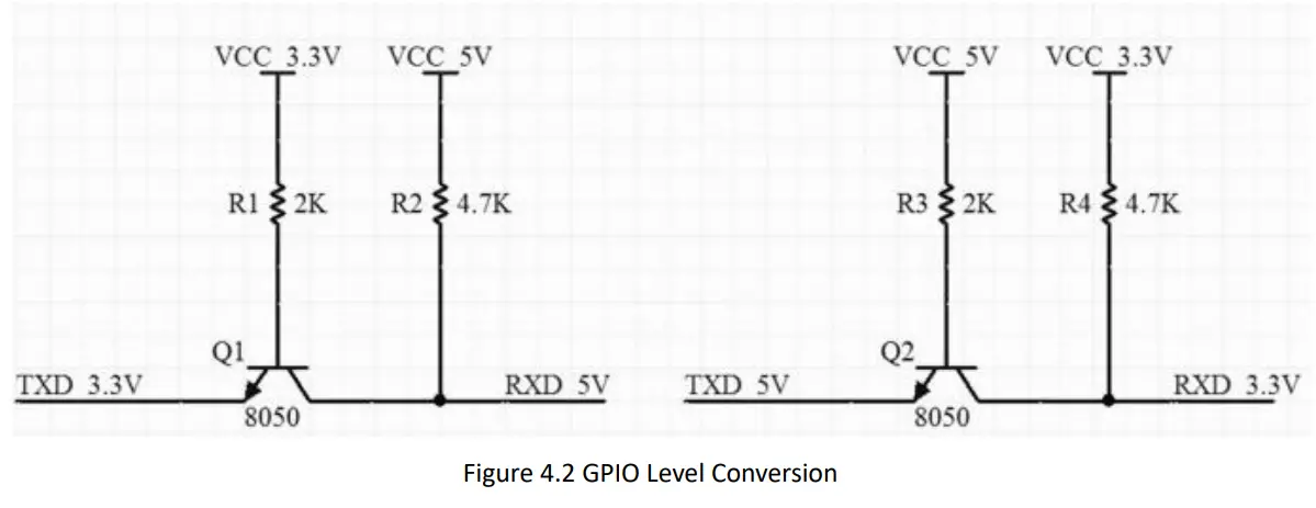
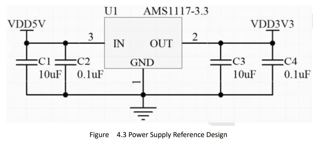
4.2 GPIO Level Conversion4.3 Power Supply Reference Design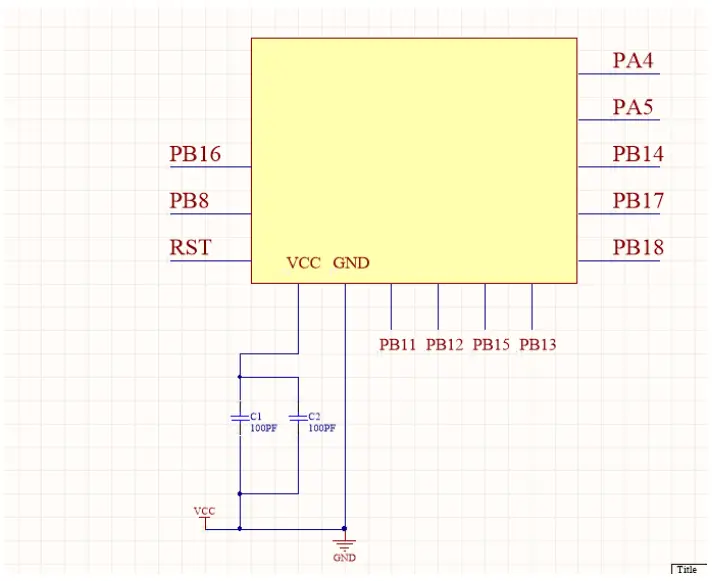
4.4 Automatically Download Reference Design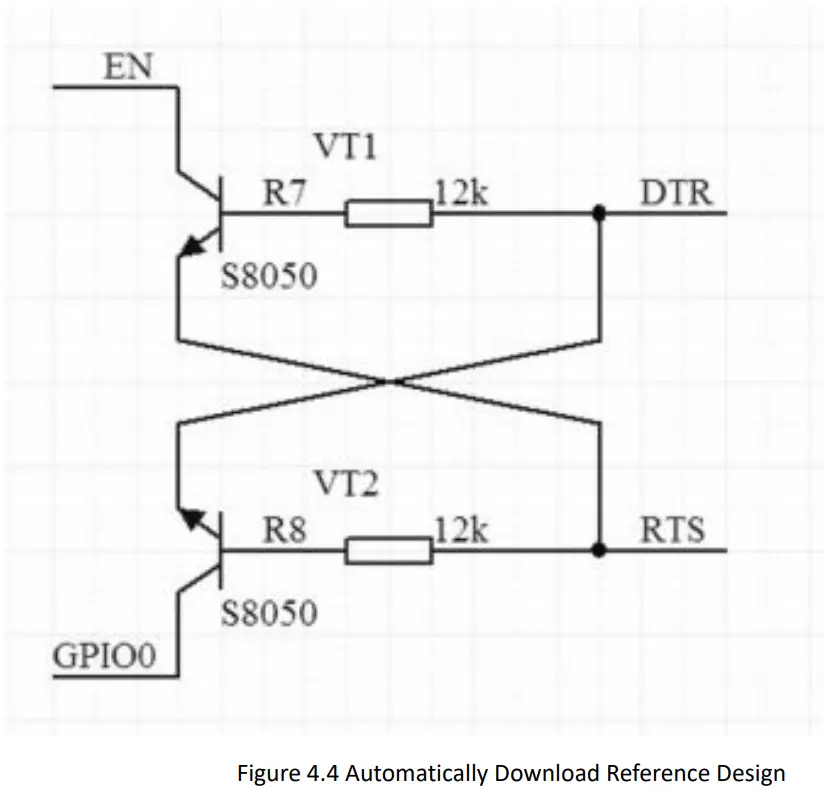 4.5 Antenna placement reference
The AW-01 module uses an onboard antenna or an external antenna in the 2.4G wi-fi frequency band. If the onboard antenna is used, the following figure shows two commonly used antenna placement methods that have less impact on the antenna performance. It is recommended to choose as much as possible One of the ways to place the module; Note: The second way of placement requires that the two sides of the PCB antenna are at least 5.0mm away from the two sides of the base plate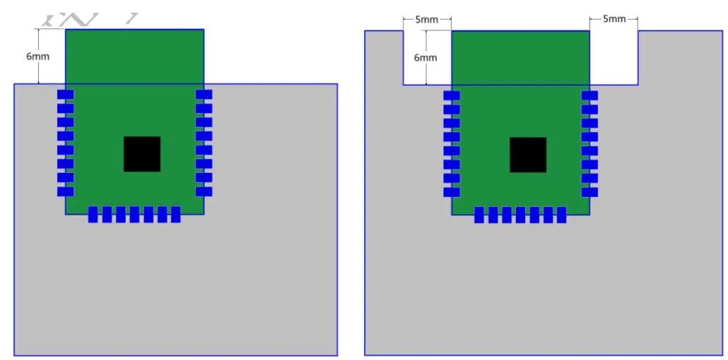 4.6 WIFI product structure design considerations
The following points should be paid attention to when placing the product board of the WIFI module in the product structure Since the metal plate and metal surface have a strong shielding effect on wireless signals, the side of the WIFI module PCB antenna must face the outside of the product in the product structure. It is forbidden to face the PCB antenna side of the WIFI module in the direction that has the shielding effect on the wireless signal, such as the PCB board and the battery;
- When installing the actual product board, the position of the WIFI module PCB antenna needs to be vertically upward;
- The WIFI module should be as far away from metal as possible in the actual product structure, such as external equipment such as transformers and motors;
- In the structural design, pay special attention to avoiding screw posts around the position of the WIFI module PCB antenna. When the screws are screwed in, it is actually equivalent to placing a metal post next to the WIFI module PCB antenna; After the actual product structure is determined, in order to achieve For the best antenna performance, it is recommended to do the antenna matching test of the whole machine.
4.7 Furnace temperature curve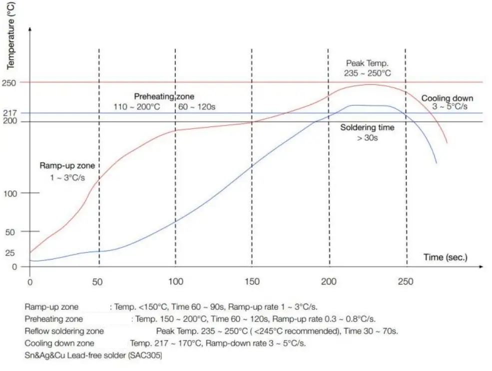
User guides
5.1 Burning download guide
Reference link https://docs.w600.fun/?p=app/download.md
5.2 AT command instructions
The W600 series module has built-in AT firmware by default, and the default baud rate is 115200. You can refer to 3.1 typical application diagram to build the minimum system circuit and then perform AT command operations.
This chapter only describes the commands, please refer to the link to the basic tutorial: https://docs.w600.fun/?p=at/esp-start.md
5.2.1 AT
| Parameters | No |
| Description | Test |
| Example | AT OK |
5.2.2 AT+GMR
| Parameters | No |
| Description | View firmware version information |
| Example | AT+GMR AT version:1.1.5( Dec 20, 2018 00:27:26) SDK version:3.0.0 things turn Technology Co., Ltd. Dec 20, 2018, 00:27:26 OK |
5.2.3 AT+RST
| Parameters | No |
| Description | Restart Module |
| Example | AT+RST |
5.2.4 AT+RESTORE
| Parameters | No |
| Description | Reset the module to factory settings |
| Example | AT+RESTORE OK |
5.3 Secondary development
The AW-01 module supports secondary development. Our company provides basic SDK packages and development documents to facilitate developers’ development. At the same time, we also provide development kits such as Aliso Things, RT Thread, Arduino, and Python.
Please refer to the link https://docs.w600.fun/?p=product/w600.md
FCC Statement
This device complies with part 15 of the FCC Rules. Operation is subject to the following two conditions: (1) This device may not cause harmful interference, and (2) this device must accept any interference received, including interference that may cause undesired operation.
Any changes or modifications not expressly approved by the party responsible for compliance could void the user’s authority to operate the equipment.
Note: This equipment has been tested and found to comply with the limits for a Class B digital device, pursuant to part 15 of the FCC Rules. These limits are designed to provide reasonable protection against harmful interference in a residential installation. This equipment generates uses and can radiate radio frequency energy and, if not installed and used in accordance with the instructions, may cause harmful interference to radio communications. However, there is no guarantee that interference will not occur in a particular installation. If this equipment does cause harmful interference to radio or television reception, which can be determined by turning the equipment off and on, the user is encouraged to try to correct the interference by one or more of the following measures:
-Reorient or relocate the receiving antenna.
-Increase the separation between the equipment and receiver.
-Connect the equipment into an outlet on a circuit different from that to which the receiver is connected.
-Consult the dealer or an experienced radio/TV technician for help.
RF warning: This equipment complies with FCC radiation exposure limits set forth for an uncontrolled environment. This equipment should be installed and operated with a minimum distance of 20cm between the radiator & your body.
Integration instructions for host product manufacturers according to KDB 996369 D03 OEM Manual v01
2.2 List of applicable FCC rules
FCC Part 15 Subpart C 15.247 & 15.209
2.3 Specific operational use conditions
The module is a WiFi module with WiFi function.
Operation Frequency: 2412-2462MHz
Number of Channel: 11
Modulation: 802.11b/g/n(HT20)/n(HT40)
Type: PCB Antenna Gain: 2.0 dBi Max. The module can be used for mobile or portable applications with a maximum 2.0dBi antenna. The host manufacturer installing this module into their product must ensure that the final composite product complies with the FCC requirements by a technical assessment or evaluation to the FCC rules, including the transmitter operation. The host manufacturer has to be aware not to provide information to the end-user regarding how to install or remove this RF module in the user’s manual of the end product which integrates this module. The end-user manual shall include all required regulatory information/warning as shown in this manual.
2.4 Limited module procedures
Not applicable. The module is a Single module and complies with the requirement of FCC Part 15.212.
2.5 Trace antenna designs
Not applicable. The module has its own antenna and doesn’t need a host’s printed board microstrip trace antenna etc.
2.6 RF exposure considerations
The module must be installed in the host equipment such that at least 20cm is maintained between the antenna and users’ body; and if RF exposure statement or module layout is changed, then the host product manufacturer is required to take responsibility of the module through a change in FCC ID or new application. The FCC ID of the module cannot be used on the final product. In these circumstances, the host manufacturer will be responsible for re-evaluating the end product (including the transmitter) and obtaining a separate FCC authorization.
2.7 Antennas
Antenna Specification are as follows:
Type: PCB Antenna
Gain: 2.0 dBi
This device is intended only for host manufacturers under the following conditions: The transmitter module may not be co-located with any other transmitter or antenna; The module shall be only used with the internal antenna(s) that has been originally tested and certified with this module. The antenna must be either permanently attached or employ a` unique’ antenna coupler.
As long as the conditions above are met, further transmitter tests will not be required. However, the host manufacturer is still responsible for testing their end-product for any additional compliance requirements required with this module installed (for example, digital device emissions, PC peripheral requirements, etc.).
2.8 Label and compliance information
Host product manufacturers need to provide a physical or e-label stating “Contains FCC ID: ATIAW01” with their finished product.
2.9 Information on test modes and additional testing requirements
Operation Frequency: 2412-2462MHz
Number of Channels: 11
Modulation: 802.11b/g/n(HT20)/n(HT40)
The host manufacturer must perform tests of radiated & conducted emission and spurious emission, etc according to the actual test modes for a stand-alone modular transmitter in a host, as well as for multiple simultaneously transmitting modules or other transmitters in a host product.
Only when all the test results of test modes comply with FCC requirements, then the end product can be sold legally.
2.10 Additional testing, Part 15 Subpart B disclaimer
The modular transmitter is only FCC authorized for FCC Part 15 Subpart C 15.247 & 15.209 and the host product manufacturer is responsible for compliance to any other FCC rules that apply to the host not covered by the modular transmitter grant of certification. If the grantee markets their product as being Part 15 Subpart B compliant (when it also contains unintentional-radiator digital circuity), then the grantee shall provide a notice stating that the final host product still requires Part 15 Subpart B compliance testing with the modular transmitter installed.
Federal Communication Commission Statement (FCC, U.S.)
This equipment has been tested and found to comply with the limits for a Class B digital device, pursuant to Part 15 of the FCC Rules. These limits are designed to provide reasonable protection against harmful interference in a residential installation. This equipment generates, uses, and can radiate radio frequency energy and, if not installed and used in accordance with the instructions, may cause harmful interference to radio communications. However, there is no guarantee that interference will not occur in a particular installation. If this equipment does cause harmful interference to radio or television reception, which can be determined by turning the equipment off and on, the user is encouraged to try to correct the interference by one of the following measures:
- Reorient or relocate the receiving antenna.
- Increase the separation between the equipment and receiver.
- Connect the equipment into an outlet on a circuit different from that to which the receiver is connected.
- Consult the dealer or an experienced radio/TV technician for help.
This device complies with Part 15 of the FCC Rules. Operation is subject to the following two conditions: (1) This device may not cause harmful interference, and (2) this device must accept any interference received, including interference that may cause undesired operation.
FCC Caution: Any changes or modifications not expressly approved by the party responsible for compliance could void the user’s authority to operate this equipment.
IMPORTANT NOTES
Co-location warning: This transmitter must not be co-located or operating in conjunction with any other antenna or transmitter.
OEM integration instructions: This device is intended only for OEM integrators under the following conditions:
The transmitter module may not be co-located with any other transmitter or antenna. The module shall be only used with the external antenna(s) that has been originally tested and certified with this module.
As long as the conditions above are met, further transmitter tests will not be required. However, the OEM integrator is still responsible for testing their end-product for any additional compliance requirements required with this module installed (for example, digital device emissions, PC peripheral requirements, etc.).
Validity of using the module certification:
In the event that these conditions cannot be met (for example certain laptop configurations or co-location with another transmitter), then the FCC authorization for this module in combination with the host equipment is no longer considered valid and the FCC ID of the module cannot be used on the final product. In these circumstances, the OEM integrator will be responsible for re-evaluating the end product (including the transmitter) and obtaining a separate FCC authorization.
End product labeling:
The final end product must be labeled in a visible area with the following: “Contains Transmitter Module FCC ID: ATI-AW01”.
Information that must be placed in the end-user manual: The OEM integrator has to be aware not to provide information to the end-user regarding how to install or remove this RF module in the user’s manual of the end product which integrates this module. The end-user manual shall include all required regulatory information/warning as show in this manual.


