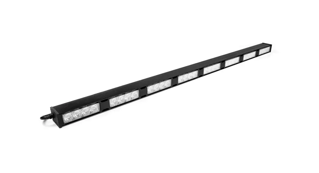
![]() Commander SE4 Traffic Director 8 Lighthead
Commander SE4 Traffic Director 8 Lighthead
User Manual
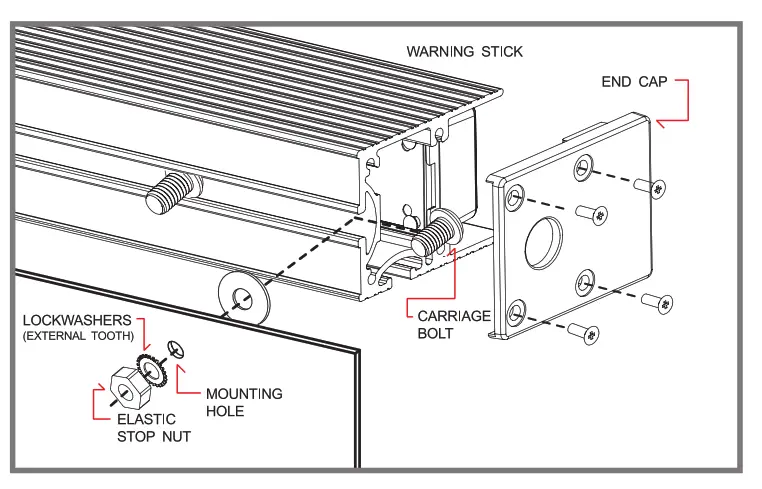
INSTALLATION
- Remove endcap (side without cable) and insert mounting carriage bolts.
- For Surface Mount, drill 1/4″ (6.3mm) holes to the mounting surface.
- Place Disk Gasket onto each bolt, and insert bolts into mounting holes.
- Place Lockwasher and Elastic Stop Nut onto each bolt, and tighten firmly.
- For Bracket Mount (sold separately), refer to mounting bracket manuals.
POWER WIRING RED
RED to +VDC (with fuse according to the following chart)
| LIGHTHEAD TYPES | 2 HEADS | 4 HEADS | 6 HEADS | 8 HEADS | 10 HEADS |
| 4-LED Lighthead | 3 Amps | 3 Amps | 5 Amps | 5 Amps | 10 Amps |
| 4-LED Lighthead | 3 Amps | 5 Amps | 10 Amps | 10 Amps | 10 Amps |
| 4-LED Lighthead | 3 Amps | 5 Amps | 10 Amps | 10 Amps | 15 Amps |
BLACK: to Chassis Ground
CONTROL WIRING FOR WARNING STICKS
WHIIT for Simultaneous or Alternating Flash
Groupl: Sticks with MOE connected to RED will flash together
Group2: Sticks with WROTE not connected to RED will flash together
*Groupl will alternate with Group2
YELLOW: for Synchronization & Flash Pattern Change (refer to Flash Patterns chart)
Connect YELLOW wires of all sticks together for synchronization *All sticks must be set at the same pattern
Note: Some patterns are not be suitable for synchronization.
| FP# | FLASH PATTERN | FP# | FLASH PATTERN | FP# | FLASH PATTERN |
| 0 | Kit Scan | 9 | Quint (split) | 18 | Mega (all) |
| 1 | Outside-In Single | 10 | Mega (split) | 19 | Ultra (all) |
| 2 | Outside-In Ultra | 11 | Ultra (split) | 20 | Single-Quad (all) |
| 3 | Side-by-Side Single | 12 | Single-Quad (split) | 21 | Single H/L (all) |
| 4 | Side-by-Side Ultra | 13 | Single H/L (split) | 22 | Steady 2 (california) |
| 5 | Random | 14 | Single (all) | 23 | Steady 4 (all) |
| 6 | Single (split) | 15 | Double (all) | 24 | Left Chaser |
| 7 | Double (split) | 16 | Quad (all) | 25 | Right Chaser |
| 8 | Quad (split) | 17 | Quint (all) |
*(split)=side by side alternating *(aII)=all LEDs on
Momentarily apply +VDC to YELLOW wire:
- Once for next pattern
- Quickly 3 times for reset to FP#0
Note: This unit is not factory set at FP#0
The following FP# are not available in 2 Head Sticks: FP# 0, 1, 2, 3, 4, 24, 25
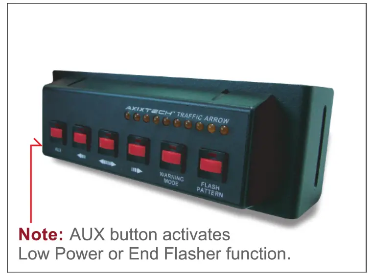
CONTROL WIRING FOR TRAFFIC ARROW STICKS
ORANGE: to +VDC for Left Arrow
ORANG E+BLUE: to +VDC for Center Out
BLUE: to +VDC for Right Arrow
BROWN: to +VDC for Warning Patterns (Arrow Function wires must be deactivated).
YELLOW : for Pattern Change (refer to Flash Patterns chart)
GREEN: to +VDC for Low Power (disconnect for High Power) or for end flasher heads on/off (only for models with end flashers)
WHOTE: only used when connecting with SW610-TA switch (sold separately)
Note: The correct side up is facing the front of the stick with wiring coming out the right side.
| FP# | ARROW PATTERNS (ORANGE/BLUE) | WARNING PATTERNS (BROWN) | END FLASHER PATTERNS (GREEN) |
| 0 | Sweep Single | Random | Random |
| 1 | Sweep Double | Outside-In Single | Single (split) |
| 2 | Sweep Triple | Outside-In Ultra | Quad (split) |
| 3 | Sweep Single End x2 | Side-by-Side Single | Mega (split) |
| 4 | Solid | Side-by-Side Ultra | Ultra (split) |
| 5 | Solid End2 | Kit Scan | Single-Quad (split) |
| 6 | Solid Chaser | Single (split) | Single (all) |
| 7 | Solid Fade | Ultra (split) | Quad (all) |
| 8 | Blink Double | Single H/L (split) | Ultra (all) |
| 9 | Blink Triple | Single (all) | Single-Quad (all) |
| 10 | Blink Solid | Ultra (all) | **In-Sync-Mode |
*(spli )=side by side alternating
*(all)=all LEDs on in-Sync-Mode:
Note: to select End Flasher Patterns, Arrow and Warning Function wires must be deactivated.
Momentarily apply +VDC to wire:
- Once for next pattern
- Quickly 3 times for reset to FP#0
Note: This unit is not factory set at FP#0 during warning mode, end flasher heads will sync according to the warning pattern.
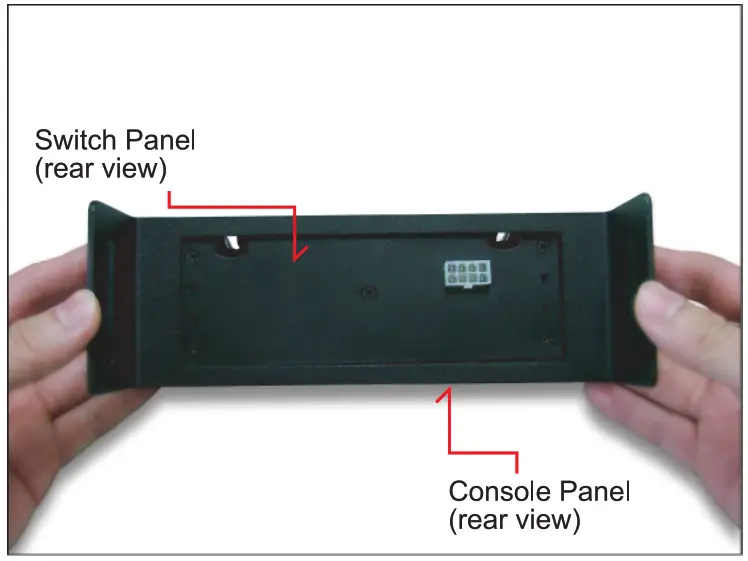
CONNECTION TO SW610-TA SWITCH PANEL (sold separately)
1. Choose a place to install the Switch Panel. 2. Route Switch Panel RED & BLACK wires toward vehicle battery. 3. Route Traffic Arrow Stick wires to Switch Panel and splice same color wires together.
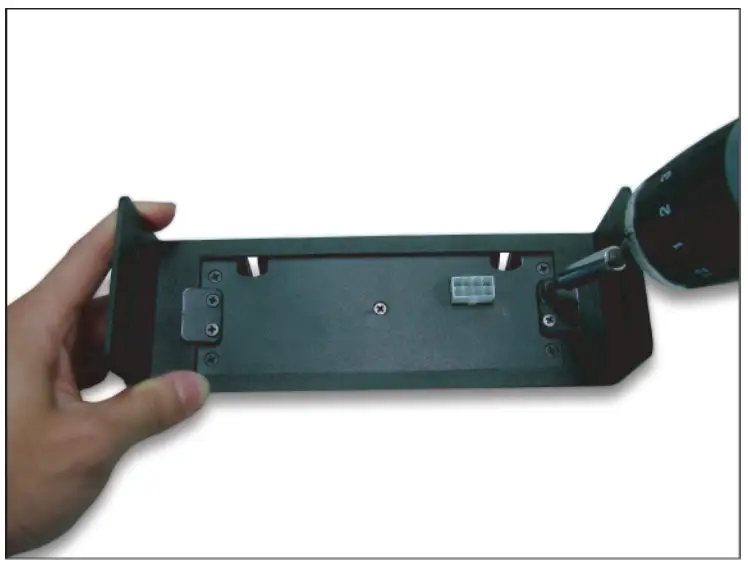
Console Mount Installation
- Check that all parts are present.

- Flip to the rear side and position Switch Panel accordingly.

- Secure Mounting Flaps with screws so that they firmly pinch the Console Panel.

- Splice wires with Traffic Arrow Stick wires and mount Console Panel onto Console.

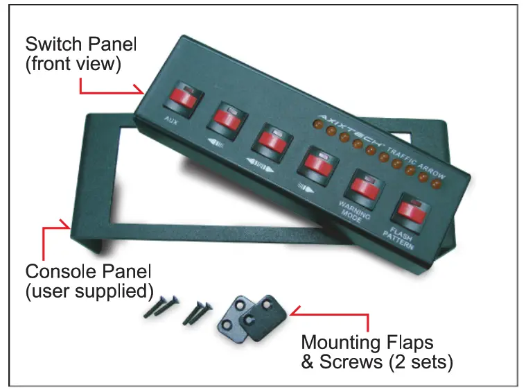
Screw Mount Installation
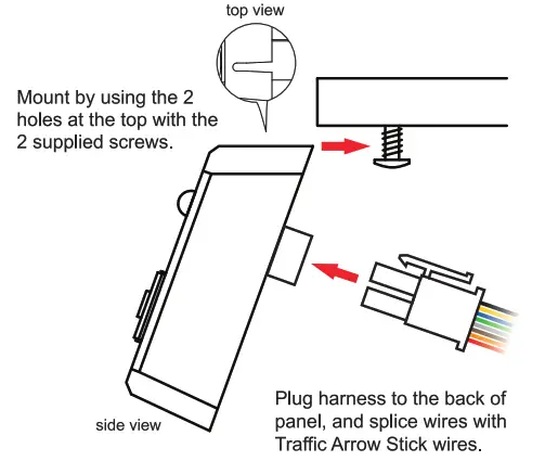
Note: do not splice RED and BLACK wires with Traffic Arrow Stick wires. They must be connected to +VDC and ground.![]()


