POTTER PAD100-SPKB Speaker Base Fire Alarm
Features
- Speaker voltage 25 or 70.7 VRMs standard, field selectable
- Field selectable power taps: 1/8W, 1/4W, 1/2W, 1W, 2W, 4W
- High quality DBA output (intelligible)
- Frequency range 400-4000 Hz
- Suitable for 520 Hz low frequency signaling applications
- Screw terminals, separate in/out wiring (18-12 gauge)
- SLC supports NFPA Class B, A and X wiring
- Tamperproof grill
- Off White Faceplate
- Product includes a 5 year warranty
Description
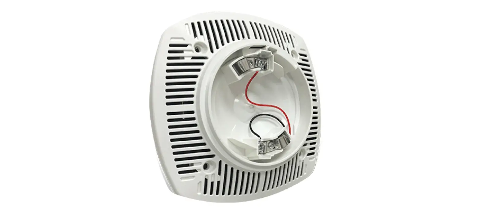
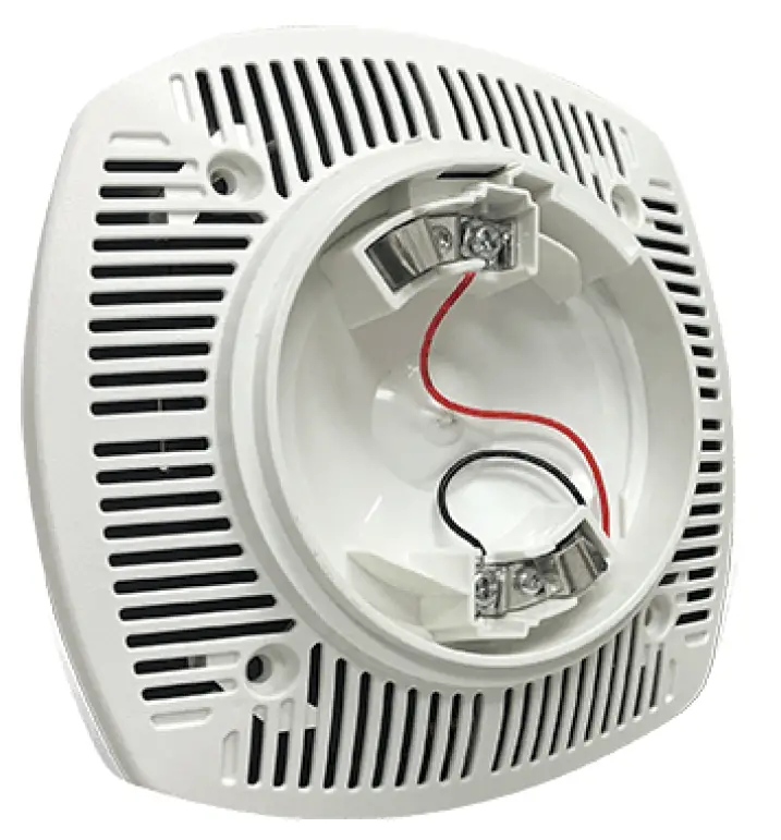
The Speaker Base (PAD100-SPKB) is a wall or ceiling mount adjustable speaker that may be utilized in a variety of applications. The speaker is designed to meet code requirements for audio and voice communications. The PAD100-SPKB offers dependable evacuation signaling. The PAD100-SPKB provides a 25 or 70.7 VRMs speaker with field selectable power taps of 1/8W, 1/4W, 1/2W, 1W, 2W or 4W. The frequency range of the PAD100-SKPB is 400-4000 Hz and is suitable for 520 Hz low frequency tone applications. The base has a locking feature for the sensor that may be used or removed in the field. The panel will support any combination of sensors or modules on the SLC. The PAD100-SPKB does not consume an address on the loop. The PAD100-SKPB can be mounted to a 4” by 2-1/8” deep square box or the LFSBBB-W back box.
The Speaker Base is not an addressable device. Independent control of the speaker base requires a PAD100-SM speaker module.
Technical Specifications
| Working Range for SLC | 24 VDC |
| Standby/Alarm Current | 150 μA |
| Installation temperature range | 32°F to 150°F (0°C to 66°C) |
| Active Current (including indicator) | 3.8 mA |
| Working Voltage | 25 Volts, 70.7 Volts |
| Power Tap Selection for SPK | 1/8 Watt , 1/4 Watt, 1/2 Watt, 1 Watt, 2 Watt, 4 Watt |
| Applicable SLC Wiring Style | Class A, Class B, Class X |
| Active Indicator | 1 LED |
| Operating relative humidity range | 0% to 93% (Non-condensing) |
| Maximum number of devices per SLC Loop | 127 |
| Dimensions (without detector) | Height: 2.75 in (70mm) Diameter: 6 in x 6 in |
| Mounting Options | Wall or Ceiling |
Detector Base Mounting
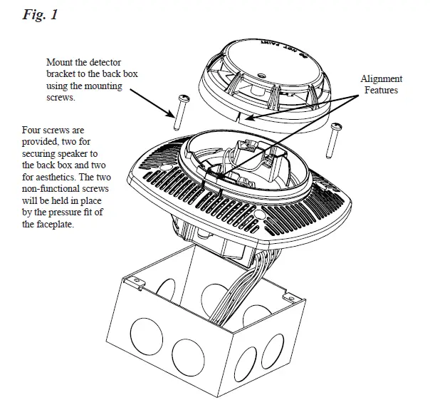
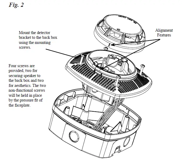
PAD100-SPKB should be mounted directly on an electrical box (see Figure 1) or the LFSBBB-W back box (see Figure 2). The PAD100-SPKB mounting holes are configured for a 4” x 2-1/8” deep square box. Use a box for each base and run the power circuit to all base locations. Fig. 1
Locking Feature
Eliminate the Locking Feature
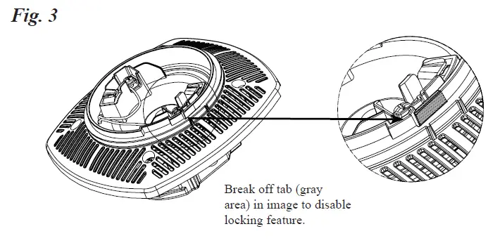
PAD100-SPKB include a locking feature that prevents removal of the detector and removal of the base cover without using a tool.
- To eliminate this feature, break off the locking tab and then install the detector. See Fig. 3. Fig. 3

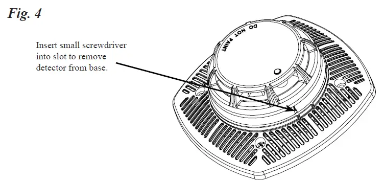
- Removing of Detector Head from Base: To remove the detector from the base once the locking feature has been activated, insert a small screwdriver into the slot on the base to push the plastic tab while simultaneously turning the detector head counter-clockwise. See Fig. 4.

- To remove the base cover from the lower enclosure once the locking feature has been activated, insert a small screwdriver into the slot on the on the base to push the plastic tab while simultaneously turning the detector head counter-clockwise.
Wiring Diagrams
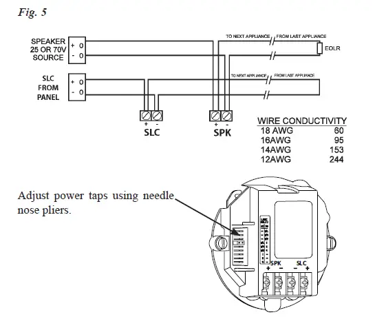
The SLC supports NFPA wiring Class B, A and X. In the Class A arrangement, two separate conductors would return from the last detector base to a listed compatible Fire Alarm Control Panel (FACP). The frequency range of the PAD100-SPKB is 400-4000Hz and is suitable for line supervision. Fig. 5
| PAD100-SPKB Field Selectable Power Tap Selection – Reverberant (dBA @ 10ft.) | ||||||
| Voltage | 1/8 Watt | 1/4 Watt | 1/2 Watt | 1 Watt | 2 Watt | 4 Watt |
| 25 Volts | 75.0 dBA | 78.1 dBA | 81.2 dBA | 83.8 dBA | 86.6 dBA | 89.7 dBA |
| 70.7 Volts | 75.1 dBA | 78.1 dBA | 80.9 dBA | 83.8 dBA | 86.9 dBA | 89.6 dBA |
System Considerations
- To select the proper wattage input for the speaker, move the jumper to the appropriate pin.
- Always maintain electrical isolation between speaker and strobe wiring on combination units.
- Do not exceed 130% of rated speaker voltage. If excessive distortion is heard, check amplifier for signal clipping. If clipping exists, reduce either amplifier input or gain.
Ordering Information
| Model | Description | Stock No. |
| PAD100-SPKB | Speaker Base | 3992762 |
| LFSBB-W | Speaker Base Back Box | 3992761 |


